2007 ISUZU KB P190 Electrical
[x] Cancel search: ElectricalPage 5649 of 6020
9A-14 SUPPLEMENTAL RESTRAINT SYSTEM
Component Description
SRS Control Unit
WARNING: DURING SERVICE PROCEDURES, BE
VERY CAREFUL WHEN HANDLING A SRS
CONTROL UNIT. NEVER STRIKE OR JAR THE SRS
CONTORL UNIT. NEVER POWER UP THE SRS
WHEN THE SRS CONTROL UNIT IS NOT RIGIDLY
ATTACHED TO THE VEHICLE. ALL SRS CONTROL
UNIT AND MOUNTING BRACKET FASTENERS
MUST BE CAREFULLY TORQUED AND THE
ARROW MUST BE POINTED TOWARD THE FRONT
OF THE VEHICLE TO ENSURE PROPER
OPERATION OF THE SRS. THE SRS CONTROL
UNIT COULD BE ACTIVATED WHEN POWERED
WHILE NOT RIGIDLY ATTACHED TO THE
VEHICLE WHICH COULD CAUSE DEPLOYMENT
AND RESULT IN PERSONAL INJURY.
The SRS control unit is designed to perform the
following functions in the SRS:
1. Energy Reserve — The SRS control unit maintains 30–Volt Loop Reserve (30VLR) energy supply to
provide deployment energy when ignition voltage is
lost in a frontal crash.
2. Frontal Crash Detection — The SRS control unit monitors vehicle velocity changes to detect frontal
crashes which are severe enough to warrant
deployment.
3. Air Bag Deployment — W hen a frontal crash o
f
sufficient force is detected, the SRS control unit
will cause enough current to flow through the ai
r
bag assembly to deploy the air bag.
4. Malfunction Detection — The SRS control unit performs diagnostic monitoring of SRS electrical
components and sets a diagnostic trouble code
when a malfunction is detected.
5. Frontal Crash Recording — The SRS control unit records information regarding SRS status during
frontal crash.
6. Malfunction Diagnosis — The SRS control unit displays SRS diagnostic trouble codes and system
status information through the use of a scan tool.
7. Driver Notification — The SRS control unit warns the vehicle driver of SRS malfunctions b
y
controlling the “SRS” warning lamp.
The SRS control unit is connected to the SRS wiring
harness by a 52–pin connector. This harness
connector uses a shorting clip across certain terminals
in the contact area. This shorting clip connects the
“SRS” warning lamp to ground when the SRS control
unit harness connector is disconnected or CP
A
(Connector Position Assurance) is not inserted even i
f
completely connected. This will cause the “SRS”
warning lamp to come “ON” steady whenever the
ignition switch is at the ON or START positions with
the SRS control unit disconnected.
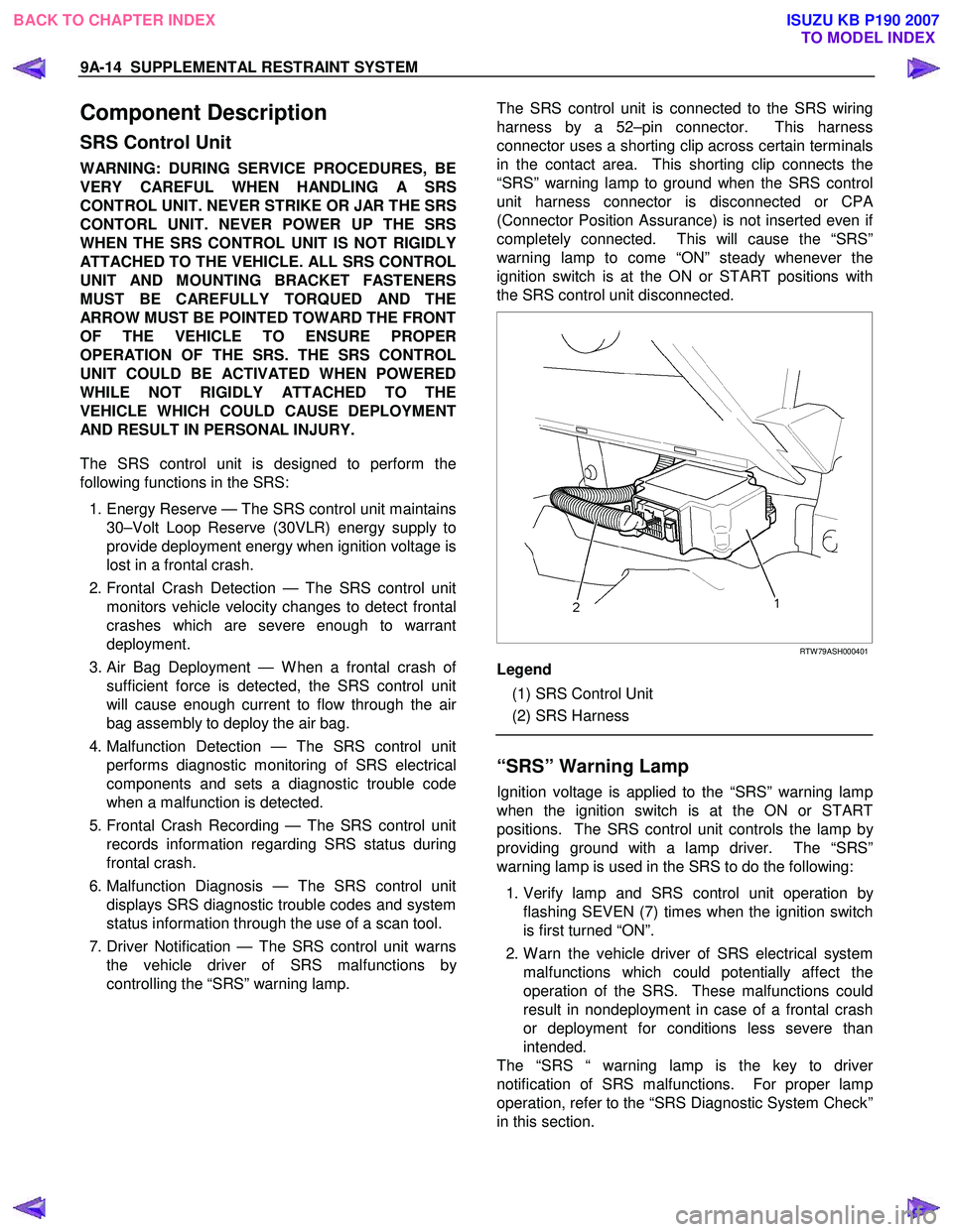
RTW 79ASH000401
Legend
(1) SRS Control Unit
(2) SRS Harness
“SRS” Warning Lamp
Ignition voltage is applied to the “SRS” warning lamp
when the ignition switch is at the ON or START
positions. The SRS control unit controls the lamp b
y
providing ground with a lamp driver. The “SRS”
warning lamp is used in the SRS to do the following:
1. Verify lamp and SRS control unit operation b
y
flashing SEVEN (7) times when the ignition switch
is first turned “ON”.
2. W arn the vehicle driver of SRS electrical system malfunctions which could potentially affect the
operation of the SRS. These malfunctions could
result in nondeployment in case of a frontal crash
or deployment for conditions less severe than
intended.
The “SRS “ warning lamp is the key to drive
r
notification of SRS malfunctions. For proper lamp
operation, refer to the “SRS Diagnostic System Check”
in this section.
BACK TO CHAPTER INDEX TO MODEL INDEXISUZU KB P190 2007
Page 5652 of 6020
SUPPLEMENTAL RESTRAINT SYSTEM 9A-17
“Continuous Monitoring”
Tests are performed by the SRS control unit on the
SRS every 100 milliseconds while “Ignition 1” voltage
is in the normal operating voltage range at the SRS
control unit.
Data Link Connector (DLC)
Formerly “DLC”, a connector which allows
communication with an external computer, such as a
scan tool.
Datum Line
A base line parallel to the plane of the underbody or
frame from which all vertical measurements originate.
Deploy
To inflate the air bag.
Deployment Loops
The circuits which supply current to the air bag
assemblies to deploy the air bag.
Diagnostic Trouble Code (DTC)
Formerly “Code”, a numerical designator used by the
SRS control unit to indicate specific SRS malfunctions.
Driver Current Source
An output of the SRS control unit which applies current
into the driver air bag assembly circuit during the
“Initiator Assembly Resistance Test”.
Driver Air Bag Assembly
An assembly located in the steering wheel hub
consisting of an inflatable bag, an inflator and an
initiator.
EEPROM
Electrically Erasable Programmable Read Onl
y
Memory. Memory which retains its contents when
power is removed from the SRS control unit.
Ignition Cycle
The voltage at the SRS control unit “Ignition 1” input,
with ignition switch “ON”, is within the normal operating
voltage range for at least ten seconds before turning
the ignition switch “OFF”.
Ignition 1
A battery voltage (B+) circuit which is only powered
when the ignition switch is in the ON, or START
position.
Initiator
The electrical component inside the air bag assembl
y
which, when sufficient current flows, sets off the
chemical reaction that inflates the air bag.
“Initiator Assembly Resistance Test”
Tests are performed once for each ignition cycle when
no malfunctions are detected during “Turn–ON” o
r
“Continuous Monitoring”. This test checks for the
correct SRS control unit configuration for the vehicle,
shorts to “Ignition 1” in the deployment loops, high
resistance or opens in the “Driver Side” and
“Passenger Side” circuits and measures the resistance
of the inflator assembly consisting of 1) Initiators, 2)
SRS coil assembly (driver side only), 3) Connectors
and associated wiring.
Normal Operating Voltage Range
The voltage measured between the SRS control unit
“Ignition 1” terminals and “Ground” terminals is
between 9 and 16 volts.
Passenger Current Source
An output of the SRS control unit which applies current
into the passenger air bag assembly circuit during the
“Initiator Assembly Resistance Test”.
Passenger Air Bag Assembly
An assembly located in the front of the passenger side
of the instrument panel consisting of an inflatable bag,
an inflator and an initiator.
Scan Tool
An external computer used to read diagnostic
information from on–board computers via the data link
connector.
SRS control unit
SRS control unit which provides reserve energy to the
deployment loops, deploys the air bags when required
and performs diagnostic monitoring of all SRS
components.
Serial Data
Information representing the status of the SRS.
SRS
Supplemental Restraint System.
SRS Coil Assembly
An assembly of two current–carrying coils in the drive
r
deployment loop that allows the rotation of the steering
wheel while maintaining the continuous contact of the
driver deployment loop to the driver air bag assembly.
SRS Wiring Harness
The wires and connectors that electrically connect the
components in the SRS.
“Turn–ON”
Test which the SRS control unit performs on the SRS
once during each ignition cycle immediately afte
r
“Ignition 1” voltage is applied to the SRS control unit
and before “Continuous Monitoring”.
BACK TO CHAPTER INDEX TO MODEL INDEXISUZU KB P190 2007
Page 5653 of 6020
9A-18 SUPPLEMENTAL RESTRAINT SYSTEM
Diagnosis
WARNING: TO AVOID DEPLOYMENT WHEN
TROUBLESHOOTING THE SRS, DO NOT USE
ELECTRICAL TEST EQUIPMENT SUCH AS
A
BATTERY–POWERED OR AC–POWERED
VOLTMETER, OHMMETER, ETC., OR ANY TYPE
OF ELECTRICAL EQUIPMENT OTHER THAN THAT
SPECIFIED IN THIS MANUAL. DO NOT USE
A
NON-POWERED PROBE–TYPE TESTER.
INSTRUCTIONS IN THIS MANUAL MUST BE
FOLLOWED CAREFULLY, OTHERWISE
PERSONAL INJURY MAY RESULT.
Diagnostic Trouble Codes
The “SRS Diagnostic System Check” must always be
the starting point of any SRS diagnosis. The “SRS
Diagnostic System Check” checks for proper “SRS”
warning lamp operation and checks for SRS
diagnostic trouble codes using the scan tool.
1. Current diagnostic trouble codes – Malfunctions that are presently being detected. Current
diagnostic trouble codes are stored in RAM
(Random Access Memory).
2. History diagnostic trouble codes – All malfunctions detected since the last time the history memor
y
was cleared. History diagnostic trouble codes are
stored in EEPROM.
Scan Tool Diagnostics
A scan tool is used to read current and history
diagnostic trouble codes and to clear all diagnostic
trouble codes after a repair is completed. The scan
tool must be updated to communicate with the SRS
through a replaceable cartridge before it can be used
for SRS diagnostics. To use the scan tool, connect it
to the data link connector and turn the ignition switch
“ON”. The scan tool reads serial data from the SRS
control unit “Serial Data” line terminal “21” to the data
link connector terminal “2”.
Use Of Special Tools
WARNING: TO AVOID DEPLOYMENT WHEN
TROUBLESHOOTING THE SRS, DO NOT USE
ELECTRICAL TEST EQUIPMENT SUCH AS
A
BATTERY–POWERED OR AC–POWERED
VOLTMETER, OHMMETER, ETC, OR ANY TYPE OF
ELECTRICAL EQUIPMENT OTHER THAN THAT
SPECIFIED IN THIS MANUAL. DO NOT USE
A
NON-POWERED PROBE–TYPE TESTER.
INSTRUCTIONS IN THIS MANUAL MUST BE
FOLLOWED CAREFULLY, OTHERWISE
PERSONAL INJURY MAY RESULT. YOU SHOULD
BE FAMILIAR WITH THE TOOLS LISTED IN THIS
SECTION UNDER THE HANDLING SRS SPECIAL
TOOLS.
You should be able to measure voltage and
resistance. You should be familiar with proper use o
f
a scan tool such as the Tech 2 Diagnostic Computer,
SRS Driver/Passenger Load Tool 5-8840-2421-0,
Connector Test Adapter Kit 5-8840-2835-0 and the
DMM (Digital Multimeter) 5-8840-0366-0.
BACK TO CHAPTER INDEX TO MODEL INDEXISUZU KB P190 2007
Page 5664 of 6020
SUPPLEMENTAL RESTRAINT SYSTEM 9A-29
5. Strip 13 mm (1/2 inch) of insulation from the yellow
– green and yellow – black wire lead of the
connector.
6. Cut two 900 cm (30 feet) deployment wires from 0.8 mm
2 (18 gauge) or thicker multi–strand wire.
These wires will be used to fabricate the drive
r
deployment harness.
7. Strip 13 mm (1/2 inch) of insulation from both ends of the wires cut in the previous step.
8. Short the wires by twisting together one end from each. Deployment wires shall remain shorted and
not be connected to a power source until the ai
r
bag is to be deployed.
WARNING: FAILURE TO FOLLOW PROCEDURES
IN THE ORDER LISTED COULD RESULT IN
PERSONAL INJURY. NEVER CONNECT
DEPLOYMENT WIRES TO ANY POWER SOURCE
BEFORE CONNECTING DEPLOYMENT WIRES TO
THE AIR BAG ASSEMBLY LEADS. DEPLOYMENT
WIRES SHALL REMAIN SHORTED AND NOT BE
CONNECTED TO A POWER SOURCE UNTIL THE
AIR BAG IS TO BE DEPLOYED. THE AIR BAG
ASSEMBLY WILL IMMEDIATELY DEPLOY THE AIR
BAG WHEN A POWER SOURCE IS CONNECTED
TO IT. WEAR SAFETY GLASSES THROUGHOUT
THIS ENTIRE DEPLOYMENT AND DISPOSAL
PROCEDURE.
9. Twist together one connector wire lead to one deployment wire. The connection should be
mechanically secure.
10. Bend the twisted connection made in the previous step flat and wrap it tightly with electrical tape to
insulate and secure.
11. Twist together, bend and tape the remaining connector wire lead to the remaining deployment
wire.
12. Connect the deployment harness to the driver ai
r
bag assembly yellow connector at the base of the
steering column. Route the deployment harness
out through the driver’s side of the vehicle.
WARNING: DEPLOYMENT WIRES SHALL REMAIN
SHORTED AND NOT BE CONNECTED TO
A
POWER SOURCE UNTIL THE AIR BAG IS TO BE
DEPLOYED.
THE AIR BAG ASSEMBLY WILL IMMEDIATELY
DEPLOY THE AIR BAG WHEN A POWER SOURCE
IS CONNECTED TO IT.
Connecting the deployment wires to the powe
r
source should always be the final step in the ai
r
bag assembly deployment procedure.
Failure to follow procedures in the order listed
could result in personal injury.
13. Disconnect the passenger air bag assembly yello
w
connector located behind the glove box assembly.
14. Cut the passenger air bag assembly harness
connector from the vehicle leaving at least 15 cm
(six inches) of wire at the connector.
15. Strip 13 mm (1/2 inch) of insulation from the blue– white and pink–blue wire lead of the connector.
16. Cut two 900 cm (30 feet) deployment wires from 0.8 mm
2 (18 gauge) or thicker multi–strand wire.
These wires will be used to fabricate the
passenger deployment harness.
17. Strip 13 mm (1/2 inch) of insulation from both ends of the wires cut in the previous step.
18. Short the wires by twisting together one end from each. The deployment wires shall remain shorted
and not be connected to a power source until the
air bag is to be deployed.
WARNING: FAILURE TO FOLLOW PROCEDURES
IN THE ORDER LISTED COULD RESULT IN
PERSONAL INJURY. NEVER CONNECT
DEPLOYMENT WIRES TO ANY POWER SOURCE
BEFORE CONNECTING DEPLOYMENT WIRES TO
THE AIR BAG ASSEMBLY LEADS. DEPLOYMENT
WIRES SHALL REMAIN SHORTED AND NOT BE
CONNECTED TO A POWER SOURCE UNTIL THE
AIR BAG IS TO BE DEPLOYED. THE AIR BAG
ASSEMBLY WILL IMMEDIATELY DEPLOY THE AIR
BAG WHEN A POWER SOURCE IS CONNECTED
TO IT. WEAR SAFETY GLASSES THROUGHOUT
THIS ENTIRE DEPLOYMENT AND DISPOSAL
PROCEDURE.
19. Twist together one connector wire lead to one deployment wire. The connection should be
mechanically secure.
20. Bend the twisted connection made in the previous step flat and wrap it tightly with electrical tape to
insulate and secure.
21. Twist together, bend and tape the remaining connector wire lead to the remaining deployment
wire.
22. Connect the deployment harness to the passenge
r
air bag assembly yellow connector located behind
the glove box assembly. Route the deployment
harness out through the passenger side of the
vehicle.
WARNING: DEPLOYMENT WIRES SHALL REMAIN
SHORTED AND NOT BE CONNECTED TO
A
POWER SOURCE UNTIL THE AIR BAG IS TO BE
DEPLOYED. THE AIR BAG ASSEMBLY WILL
IMMEDIATELY DEPLOY THE AIR BAG WHEN
A
POWER SOURCE IS CONNECTED TO IT.
CONNECTING THE DEPLOYMENT WIRES
SHOULD ALWAYS BE THE FINAL STEP IN THE
AIR BAG ASSEMBLY DEPLOYMENT PROCEDURE.
FAILURE TO FOLLOW PROCEDURES IN THE
ORDER LISTED COULD RESULT IN PERSONAL
INJURY.
BACK TO CHAPTER INDEX TO MODEL INDEXISUZU KB P190 2007
Page 5680 of 6020
SUPPLEMENTAL RESTRAINT SYSTEM 9A-45
Special Tools
WARNING: TO AVOID DEPLOYMENT WHEN
TROUBLESHOOTING THE SRS, DO NOT USE
ELECTRICAL TEST EQUIPMENT SUCH AS
A
BATTERY–POWERED OR AC–POWERED
VOLTMETER, OHMMETER, ETC., OR ANY TYPE
OF ELECTRICAL EQUIPMENT OTHER THAN THAT
SPECIFIED IN THIS MANUAL. DO NOT USE AN
UNPOWERED PROBE–TYPE TESTER.
INSTRUCTIONS IN THIS MANUAL MUST BE
FOLLOWED CAREFULLY, OTHERWISE
PERSONAL INJURY MAY RESULT.
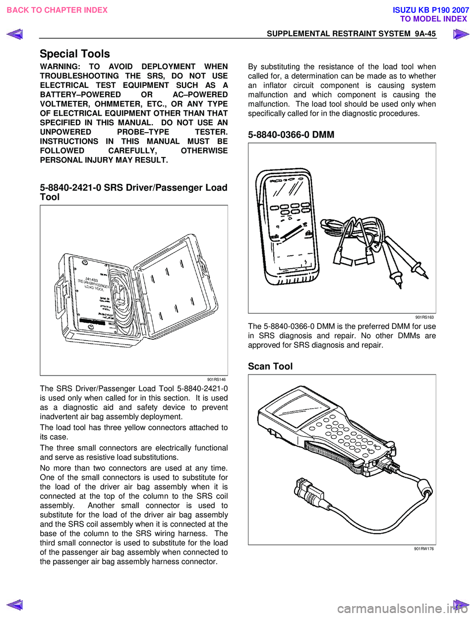
5-8840-2421-0 SRS Driver/Passenger Load
Tool
901RS146
The SRS Driver/Passenger Load Tool 5-8840-2421-0
is used only when called for in this section. It is used
as a diagnostic aid and safety device to prevent
inadvertent air bag assembly deployment.
The load tool has three yellow connectors attached to
its case.
The three small connectors are electrically functional
and serve as resistive load substitutions.
No more than two connectors are used at any time.
One of the small connectors is used to substitute fo
r
the load of the driver air bag assembly when it is
connected at the top of the column to the SRS coil
assembly. Another small connector is used to
substitute for the load of the driver air bag assembl
y
and the SRS coil assembly when it is connected at the
base of the column to the SRS wiring harness. The
third small connector is used to substitute for the load
of the passenger air bag assembly when connected to
the passenger air bag assembly harness connector.
By substituting the resistance of the load tool when
called for, a determination can be made as to whethe
r
an inflator circuit component is causing system
malfunction and which component is causing the
malfunction. The load tool should be used only when
specifically called for in the diagnostic procedures.
5-8840-0366-0 DMM
901RS163
The 5-8840-0366-0 DMM is the preferred DMM for use
in SRS diagnosis and repair. No other DMMs are
approved for SRS diagnosis and repair.
Scan Tool
901RW 176
BACK TO CHAPTER INDEX TO MODEL INDEXISUZU KB P190 2007
Page 5683 of 6020
RESTRAINT CONTROL SYSTEM 9A1-1
SECTION 9A1
RESTRAINT CONTROL SYSTEM
TABLE OF CONTENTS
PAGE
Service Precaution ............................................................................................................. ..........9A1- 2
Diagnosis In formation ......................................................................................................... ........9A1- 3
Diagnostic Procedures .......................................................................................................... ......9A1- 3
Diagnostic Codes ............................................................................................................... ..........9A1- 3
How To Read Trouble Codes ..................................................................................................... .9A1- 3
How To Clear Trouble Codes .................................................................................................... ..9A1- 3
Scan Tool Di agnostics .......................................................................................................... .......9A1- 3
Basic Knowledge Required ....................................................................................................... ..9A1- 4
Basic Electrical Circuits ..................................................................................................... .........9A1- 4
"Flash Code" Diagnostics ...................................................................................................... ....9A1- 4
DATA LIST (Tech2) .............................................................................................................. .........9A1- 5
Diagnostic Trouble Codes ....................................................................................................... ....9A1- 6
System Schematic .............................................................................................................. .........9A 1- 7
SRS Diagnostic System Check ...................................................................................................9 A1- 7
Chart A SRS control uni t Integrity Check...................................................................................9A1- 10
Chart B "SRS" Warning Lamp Comes "ON" Steady..................................................................9A1- 12
Chart C "SRS" Warning Lamp Does Not Come "ON" Steady ..................................................9A1-14
DTC B0015 (Flash Code 15) Passenger Air Ba g Squib Circuit High Resistance ...................9A1-17
DTC B0016 (Flash Code 16) Passenger Air Ba g Squib Circuit Low Resistance .....................9A1-20
DTC B0018 (Flash Code 18) Passenger Air Ba g Squib Circuit Short to GND.........................9A1-23
DTC B0019 (Flash Code 19) Passenger Air Bag Squib Circuit Short to Battery
Voltage ........................................................................................................................ ..................9A1- 26
DTC B0021 (Flash Code 21) Driver Air Ba g Squib Circuit High Resistance ............................9A1-28
DTC B0022 (Flash Code 22) Driver Air Ba g Squib Circuit Low Resistance.............................9A1-31
DTC B0025 (Flash Code 25) Driver Air Ba g Squib Circuit Short to GND ................................9A1-34
DTC B0026 (Flash Code 26) Driver Air Bag Squib Circuit Short to Battery
Voltage ........................................................................................................................ ..................9A1- 37
BACK TO CHAPTER INDEX
TO MODEL INDEX
ISUZU KB P190 2007
Page 5685 of 6020
RESTRAINT CONTROL SYSTEM 9A1-3
Diagnostic Information
CAUTION: When fasteners are removed, always
reinstall them at the same location from which they
were removed. If a fastener needs to be replaced,
use the correct part number fastener for that
application. If the correct part number fastener is
not available, a fastener of equal size and strength
(or stronger) may be used. Fasteners that are not
reused, and those requiring thread locking
compound, will be called out. The correct torque
value must be used when installing fasteners that
require it. If the above conditions are not followed,
parts or system damage could result.
Diagnostic Procedures
WARNING: TO AVOID DEPLOYMENT WHEN
TROUBLESHOOTING THE SRS, DO NOT USE
ELECTRICAL TEST EQUIPMENT SUCH AS
A
BATTERY-POWERED OR AC-POWERED
VOLTMETER, OHMMETER, ETC., OR ANY TYPE OF
ELECTRICAL EQUIPMENT OTHER THAN THAT
SPECIFIED IN THIS MANUAL. DO NOT USE A NON-
POWERED, PROBE-TYPE TESTER.
INSTRUCTIONS IN THIS MANUAL MUST BE
FOLLOWED CAREFULLY, OTHERWISE PERSONAL
INJURY MAY RESULT.
The diagnostic procedures used in this section are
designed to aid in finding and repairing SRS problems.
Outlined below are the steps to find and repair SRS
problems quickly and effectively. Failure to carefull
y
follow these procedures may result in extended
diagnostic time, incorrect diagnosis and incorrect parts
replacement.
1. Perform The “SRS Diagnostic System Check”.
The “SRS Diagnostic System Check” should always be the starting point of any SRS diagnostics. The
“SRS Diagnostic System Check” checks for prope
r
“SRS” warning lamp operation and checks for SRS
trouble codes using both “Flash Code” and “Scan
Tool” Methods.
2. Refer To The Proper Diagnostic Chart As Directed By The “SRS Diagnostic System
Check”.
The “SRS Diagnostic System Check” will lead you to the correct chart to diagnose any SRS problems.
Bypassing these procedures may result in extended
diagnostic time, incorrect diagnosis and incorrect
parts replacement.
3. Repeat The “SRS Diagnostic System Check”
After Any Repair Or Diagnostic Procedures Has
Been Performed.
Performing the “SRS Diagnostic System Check” after all repairs or diagnostic procedures, will assure
that the repair has been made correctly and that no
other conditions exist.
Diagnostic Codes
The SRS control unit maintains a history record of all
diagnostic codes that have been detected since the
SRS codes were last cleared during service.
1. Active Codes - Faults that are presently detected in this ignition cycle. Active codes are stored in RAM
(Random Access Memory).
2. History Codes - All faults detected since the last time the history fault memory was cleared. History codes
are stored in the EEPROM. (Electronically Erasable
Programmable Read only Memory)
How To Read Trouble Codes
All codes (Active and history) can be read (or cleared)
by using a scan tool or equivalent.
If a PDT is not available, have the vehicle serviced by a
HOLDEN dealer.
How To Clear Trouble Codes
Trouble codes can only be cleared by using a Scan
Tool. If a “scan tool” is not available then inform the
owner of the stored codes and suggest that the codes
are cleared upon the next visit to a ISUZU/GM
dealership.
Scan Tool Diagnostics
A scan tool can be used to read current and history
codes and to clear all history codes after a repair is
complete. The scan tool must be updated to
communicate with the SRS through a replaceable
cartridge or a manufacturer's update before it can be
used for SRS diagnostics. To use the scan tool,
connect it to the DLC and turn the ignition switch “ON”.
Then follow the manufacturer's directions fo
r
communication with the SRS. The scan tool reads
serial data from the SRS control unit’s “Serial Data”
output (terminal 21) to the DLC (terminal 2).
BACK TO CHAPTER INDEX TO MODEL INDEX
ISUZU KB P190 2007
Page 5686 of 6020
9A1-4 RESTRAINT CONTROL SYSTEM
Basic Knowledge Required
Before using this section of the Service Manual, some
basic knowledge is required. W ithout this knowledge,
you will have trouble using the diagnostic procedures in
this section. Use care to prevent any harm or unwanted
deployment. Read all cautions in the service manual
and on warning labels attached to SRS components.
Basic Electrical Circuits
You should understand the basic theory of electricity
including series and parallel circuits, and understand
the voltage drops across series resistors. You should
know the meaning of voltage (volts), current (amps),
and resistance (ohms). You should understand what
happens in a circuit with an open or a shorted wire. You
should be able to read and understand a wiring
diagram.
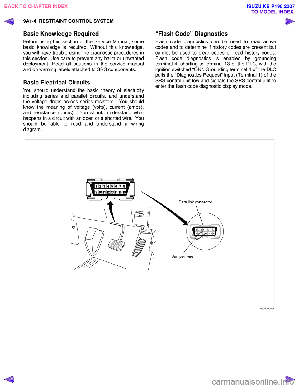
“Flash Code” Diagnostics
Flash code diagnostics can be used to read active
codes and to determine if history codes are present but
cannot be used to clear codes or read history codes.
Flash code diagnostics is enabled by grounding
terminal 4, shorting to terminal 13 of the DLC, with the
ignition switched “ON”. Grounding terminal 4 of the DLC
pulls the “Diagnostics Request” input (Terminal 1) of the
SRS control unit low and signals the SRS control unit to
enter the flash code diagnostic display mode.
060R300052
BACK TO CHAPTER INDEX TO MODEL INDEX
ISUZU KB P190 2007