2007 ISUZU KB P190 Electrical
[x] Cancel search: ElectricalPage 5690 of 6020
9A1-8 RESTRAINT CONTROL SYSTEM
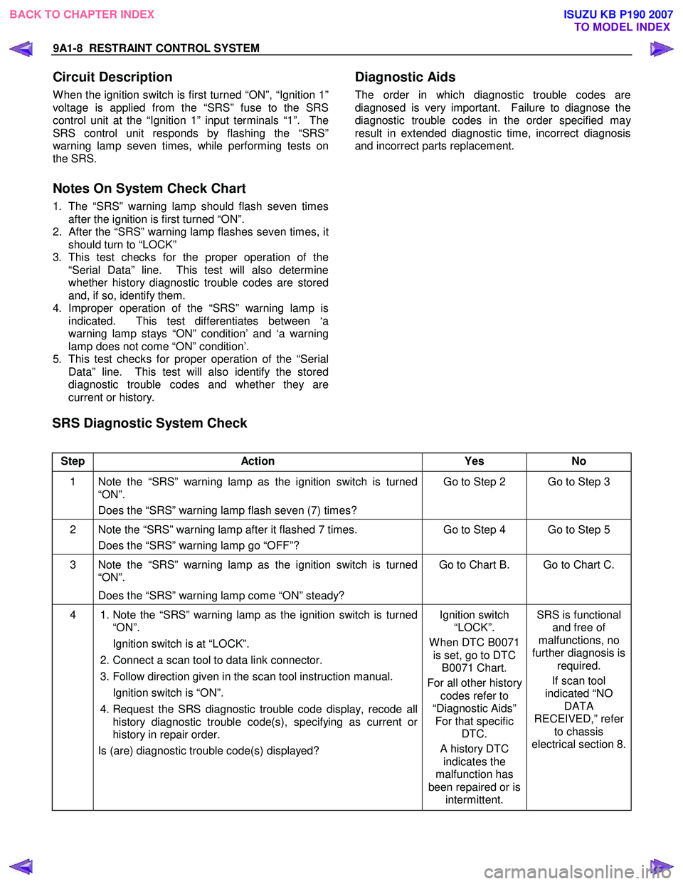
Circuit Description
W hen the ignition switch is first turned “ON”, “Ignition 1”
voltage is applied from the “SRS” fuse to the SRS
control unit at the “Ignition 1” input terminals “1”. The
SRS control unit responds by flashing the “SRS”
warning lamp seven times, while performing tests on
the SRS.
Notes On System Check Chart
1. The “SRS” warning lamp should flash seven times after the ignition is first turned “ON”.
2.
After the “SRS” warning lamp flashes seven times, it
should turn to “LOCK”
3. This test checks for the proper operation of the “Serial Data” line. This test will also determine
whether history diagnostic trouble codes are stored
and, if so, identify them.
4. Improper operation of the “SRS” warning lamp is indicated. This test differentiates between ‘a
warning lamp stays “ON” condition’ and ‘a warning
lamp does not come “ON” condition’.
5. This test checks for proper operation of the “Serial Data” line. This test will also identify the stored
diagnostic trouble codes and whether they are
current or history.
Diagnostic Aids
The order in which diagnostic trouble codes are
diagnosed is very important. Failure to diagnose the
diagnostic trouble codes in the order specified ma
y
result in extended diagnostic time, incorrect diagnosis
and incorrect parts replacement.
SRS Diagnostic System Check
Step Action Yes No
1 Note the “SRS” warning lamp as the ignition switch is turned
“ON”.
Does the “SRS” warning lamp flash seven (7) times? Go to Step 2 Go to Step 3
2 Note the “SRS” warning lamp after it flashed 7 times.
Does the “SRS” warning lamp go “OFF”? Go to Step 4 Go to Step 5
3 Note the “SRS” warning lamp as the ignition switch is turned
“ON”.
Does the “SRS” warning lamp come “ON” steady? Go to Chart B. Go to Chart C.
4
1. Note the “SRS” warning lamp as the ignition switch is turned
“ON”.
Ignition switch is at “LOCK”.
2. Connect a scan tool to data link connector.
3. Follow direction given in the scan tool instruction manual.
Ignition switch is “ON”.
4. Request the SRS diagnostic trouble code display, recode all
history diagnostic trouble code(s), specifying as current or
history in repair order.
Is (are) diagnostic trouble code(s) displayed?
Ignition switch
“LOCK”.
W hen DTC B0071 is set, go to DTC B0071 Chart.
For all other history codes refer to
“Diagnostic Aids” For that specific DTC.
A history DTC indicates the
malfunction has
been repaired or is intermittent. SRS is functional
and free of
malfunctions, no
further diagnosis is required.
If scan tool
indicated “NO DATA
RECEIVED,” refer to chassis
electrical section 8.
BACK TO CHAPTER INDEX TO MODEL INDEX
ISUZU KB P190 2007
Page 5691 of 6020
RESTRAINT CONTROL SYSTEM 9A1-9
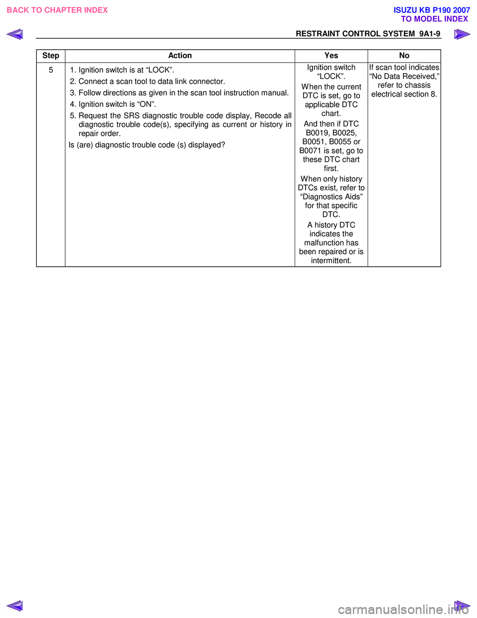
Step Action Yes No
5 1. Ignition switch is at “LOCK”.
2. Connect a scan tool to data link connector.
3. Follow directions as given in the scan tool instruction manual.
4. Ignition switch is “ON”.
5. Request the SRS diagnostic trouble code display, Recode all diagnostic trouble code(s), specifying as current or history in
repair order.
Is (are) diagnostic trouble code (s) displayed? Ignition switch
“LOCK”.
W hen the current DTC is set, go to applicable DTC chart.
And then if DTC B0019, B0025,
B0051, B0055 or
B0071 is set, go to these DTC chart first.
W hen only history
DTCs exist, refer to “Diagnostics Aids” for that specific DTC.
A history DTC indicates the
malfunction has
been repaired or is intermittent. If scan tool indicates
“No Data Received,” refer to chassis
electrical section 8.
BACK TO CHAPTER INDEX TO MODEL INDEX
ISUZU KB P190 2007
Page 5744 of 6020
9A1-62 RESTRAINT CONTROL SYSTEM
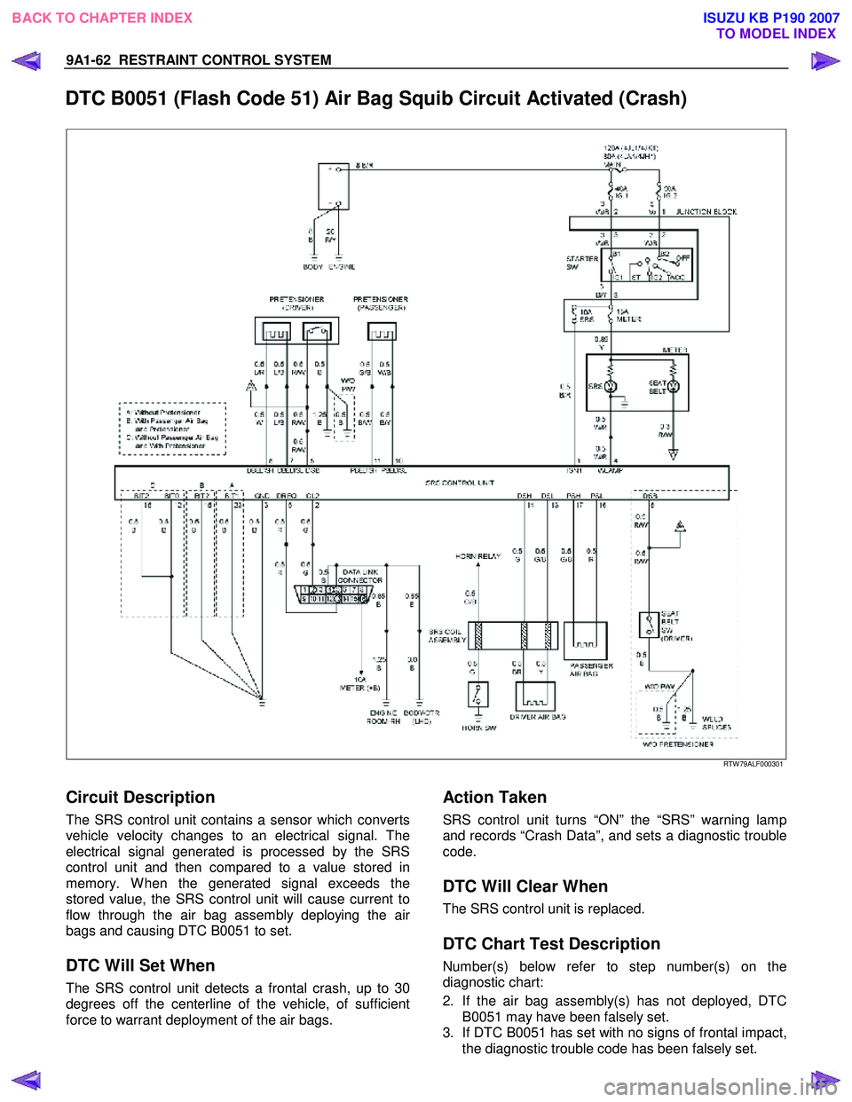
DTC B0051 (Flash Code 51) Air Bag Squib Circuit Activated (Crash)
RTW 79ALF000301
Circuit Description
The SRS control unit contains a sensor which converts
vehicle velocity changes to an electrical signal. The
electrical signal generated is processed by the SRS
control unit and then compared to a value stored in
memory. W hen the generated signal exceeds the
stored value, the SRS control unit will cause current to
flow through the air bag assembly deploying the ai
r
bags and causing DTC B0051 to set.
DTC Will Set When
The SRS control unit detects a frontal crash, up to 30
degrees off the centerline of the vehicle, of sufficient
force to warrant deployment of the air bags.
Action Taken
SRS control unit turns “ON” the “SRS” warning lamp
and records “Crash Data”, and sets a diagnostic trouble
code.
DTC Will Clear When
The SRS control unit is replaced.
DTC Chart Test Description
Number(s) below refer to step number(s) on the
diagnostic chart:
2. If the air bag assembly(s) has not deployed, DTC
B0051 may have been falsely set.
3. If DTC B0051 has set with no signs of frontal impact,
the diagnostic trouble code has been falsely set.
BACK TO CHAPTER INDEX
TO MODEL INDEX
ISUZU KB P190 2007
Page 5746 of 6020
9A1-64 RESTRAINT CONTROL SYSTEM
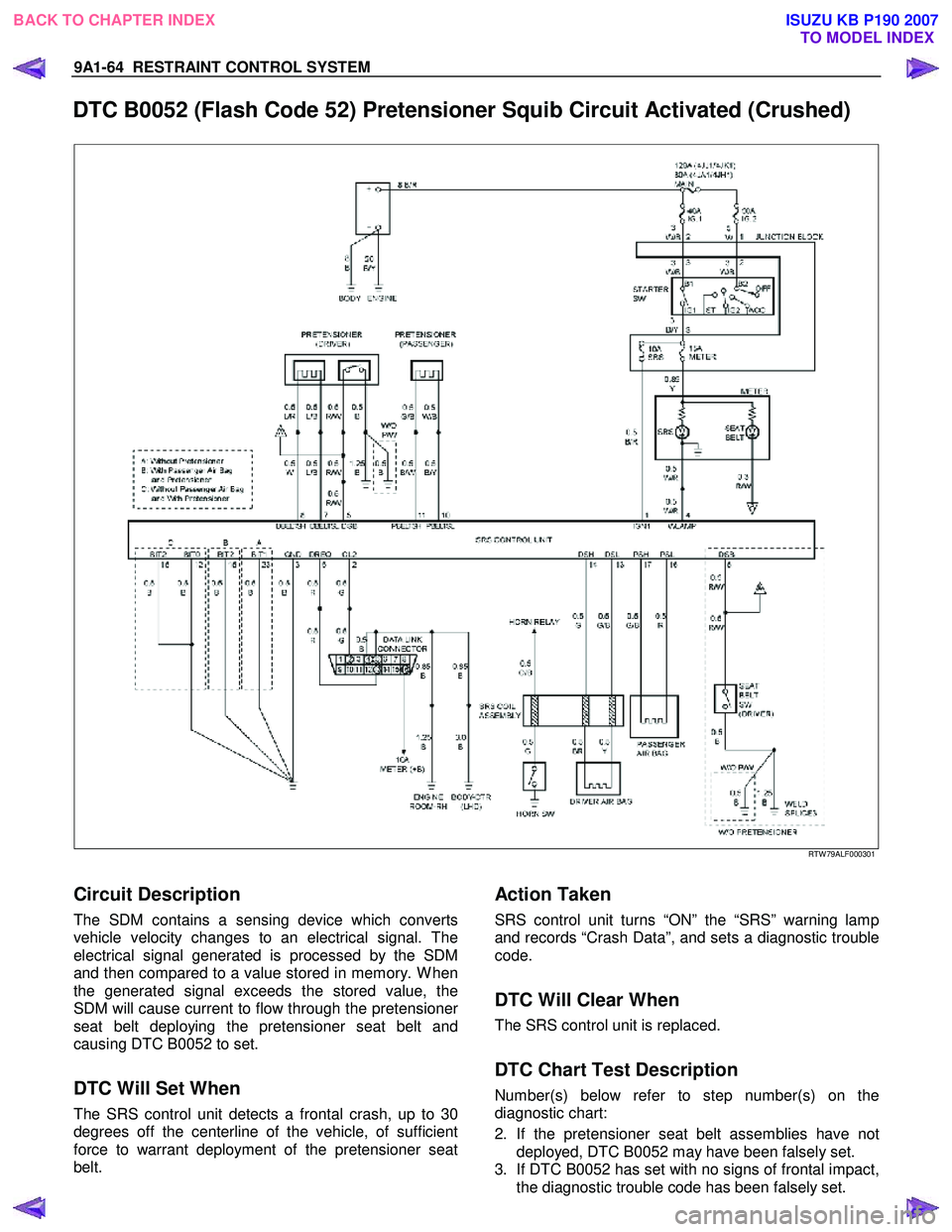
DTC B0052 (Flash Code 52) Pretensioner Squib Circuit Activated (Crushed)
RTW 79ALF000301
Circuit Description
The SDM contains a sensing device which converts
vehicle velocity changes to an electrical signal. The
electrical signal generated is processed by the SDM
and then compared to a value stored in memory. W hen
the generated signal exceeds the stored value, the
SDM will cause current to flow through the pretensione
r
seat belt deploying the pretensioner seat belt and
causing DTC B0052 to set.
DTC Will Set When
The SRS control unit detects a frontal crash, up to 30
degrees off the centerline of the vehicle, of sufficient
force to warrant deployment of the pretensioner seat
belt.
Action Taken
SRS control unit turns “ON” the “SRS” warning lamp
and records “Crash Data”, and sets a diagnostic trouble
code.
DTC Will Clear When
The SRS control unit is replaced.
DTC Chart Test Description
Number(s) below refer to step number(s) on the
diagnostic chart:
2. If the pretensioner seat belt assemblies have not deployed, DTC B0052 may have been falsely set.
3. If DTC B0052 has set with no signs of frontal impact, the diagnostic trouble code has been falsely set.
BACK TO CHAPTER INDEX TO MODEL INDEX
ISUZU KB P190 2007
Page 5754 of 6020
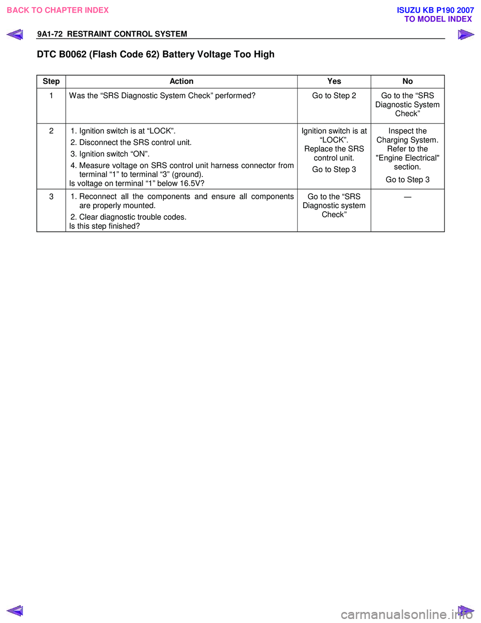
9A1-72 RESTRAINT CONTROL SYSTEM
DTC B0062 (Flash Code 62) Battery Voltage Too High
Step Action Yes No
1 W as the “SRS Diagnostic System Check” performed? Go to Step 2 Go to the “SRS
Diagnostic System Check”
2 1. Ignition switch is at “LOCK”.
2. Disconnect the SRS control unit.
3. Ignition switch “ON”.
4. Measure voltage on SRS control unit harness connector from terminal “1” to terminal “3” (ground).
Is voltage on terminal “1” below 16.5V? Ignition switch is at
“LOCK”.
Replace the SRS control unit.
Go to Step 3 Inspect the
Charging System. Refer to the
"Engine Electrical" section.
Go to Step 3
3 1. Reconnect all the components and ensure all components
are properly mounted.
2. Clear diagnostic trouble codes.
Is this step finished? Go to the “SRS
Diagnostic system Check” ―
BACK TO CHAPTER INDEX
TO MODEL INDEX
ISUZU KB P190 2007
Page 5756 of 6020
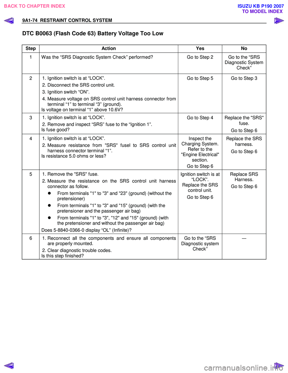
9A1-74 RESTRAINT CONTROL SYSTEM
DTC B0063 (Flash Code 63) Battery Voltage Too Low
Step Action Yes No
1 W as the “SRS Diagnostic System Check” performed? Go to Step 2 Go to the “SRS
Diagnostic System Check”
2 1. Ignition switch is at “LOCK”.
2. Disconnect the SRS control unit.
3. Ignition switch “ON”.
4. Measure voltage on SRS control unit harness connector from terminal “1” to terminal “3” (ground).
Is voltage on terminal “1” above 10.6V? Go to Step 5 Go to Step 3
3
1. Ignition switch is at “LOCK”.
2. Remove and inspect “SRS” fuse to the “Ignition 1”.
Is fuse good? Go to Step 4 Replace the "SRS"
fuse.
Go to Step 6
4
1. Ignition switch is at “LOCK”.
2. Measure resistance from "SRS" fusel to SRS control unit
harness connector terminal “1”.
Is resistance 5.0 ohms or less? Inspect the
Charging System. Refer to the
"Engine Electrical" section.
Go to Step 6 Replace the SRS
harness.
Go to Step 6
5
1. Remove the "SRS" fuse.
2. Measure the resistance on the SRS control unit harness connector as follow.
�z From terminals "1" to "3" and "23" (ground) (without the
pretensioner)
�z From terminals "1" to "3" and "15" (ground) (with the
pretensioner and the passenger air bag)
�z From terminals "1" to "3", "12" and "15" (ground) (with
the pretensioner and without the passenger air bag)
Does 5-8840-0366-0 display “OL” (Infinite)? Ignition switch is at
“LOCK”.
Replace the SRS control unit.
Go to Step 6 Replace SRS
Harness.
Go to Step 6
6 1. Reconnect all the components and ensure all components
are properly mounted.
2. Clear diagnostic trouble codes.
Is this step finished? Go to the “SRS
Diagnostic system Check” ―
BACK TO CHAPTER INDEX
TO MODEL INDEX
ISUZU KB P190 2007
Page 5873 of 6020
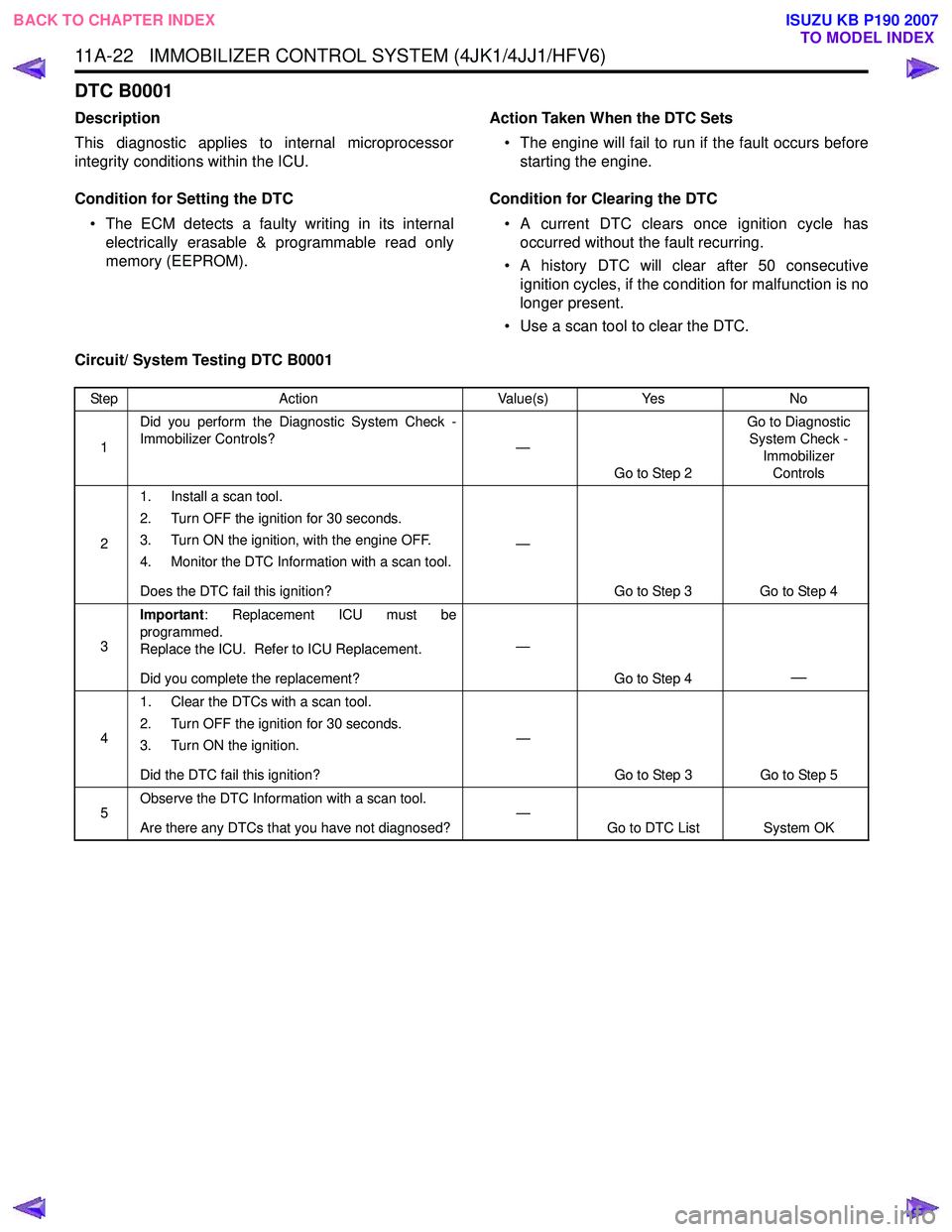
11A-22 IMMOBILIZER CONTROL SYSTEM (4JK1/4JJ1/HFV6)
DTC B0001
Description
This diagnostic applies to internal microprocessor
integrity conditions within the ICU.
Condition for Setting the DTC • The ECM detects a faulty writing in its internal electrically erasable & programmable read only
memory (EEPROM). Action Taken When the DTC Sets
• The engine will fail to run if the fault occurs before starting the engine.
Condition for Clearing the DTC • A current DTC clears once ignition cycle has occurred without the fault recurring.
• A history DTC will clear after 50 consecutive ignition cycles, if the condition for malfunction is no
longer present.
• Use a scan tool to clear the DTC.
Circuit/ System Testing DTC B0001
Step Action Value(s)Yes No
1 Did you perform the Diagnostic System Check -
Immobilizer Controls? —
Go to Step 2 Go to Diagnostic
System Check - Immobilizer
Controls
2 1. Install a scan tool.
2. Turn OFF the ignition for 30 seconds.
3. Turn ON the ignition, with the engine OFF.
4. Monitor the DTC Information with a scan tool.
Does the DTC fail this ignition? —
Go to Step 3 Go to Step 4
3 Important
: Replacement ICU must be
programmed.
Replace the ICU. Refer to ICU Replacement.
Did you complete the replacement? —
Go to Step 4
—
41. Clear the DTCs with a scan tool.
2. Turn OFF the ignition for 30 seconds.
3. Turn ON the ignition.
Did the DTC fail this ignition? —
Go to Step 3 Go to Step 5
5 Observe the DTC Information with a scan tool.
Are there any DTCs that you have not diagnosed? —
Go to DTC List System OK
BACK TO CHAPTER INDEX
TO MODEL INDEX
ISUZU KB P190 2007
Page 5874 of 6020

IMMOBILIZER CONTROL SYSTEM (4JK1/4JJ1/HFV6) 11A-23
DTC B0002
Description
The electrically erasable programmable read only
memory (EEPROM) memorizes immobilizer security
code and transponder key information. If the ICU
detects immobilizer security code is not programmed
into the ICU, this DTC will set.
Condition for Setting the DTC • The ICU detects that the security code is not programmed.
Action Taken When the DTC Sets • The engine will fail to run if the fault occurs before starting the engine. Condition for Clearing the DTC
• A current DTC clears once ignition cycle has occurred without the fault recurring.
• A history DTC will clear after 50 consecutive ignition cycles, if the condition for malfunction is no
longer present.
• Use a scan tool to clear the DTC.
Diagnostic Aids • Non-programmed ICU sets this DTC.
Circuit/ System Testing DTC B0002
Step Action Value(s)Yes No
1 Did you perform the Diagnostic System Check -
Immobilizer Controls? —
Go to Step 2 Go to Diagnostic
System Check - Immobilizer Controls
2 1. Install a scan tool.
2. Turn OFF the ignition for 30 seconds.
3. Turn ON the ignition, with the engine OFF.
4. Monitor the DTC Information with a scan tool.
Does the DTC fail this ignition? —
Go to Step 3 Go to Diagnostic
Aids
3 Program immobilizer security information into the
ICU. Refer to Resetting and Programming
Guidelines in this section.
Did you complete the programming? —
Go to Step 4
—
41. Clear the DTCs with a scan tool.
2. Turn OFF the ignition for 30 seconds.
3. Turn ON the ignition.
Did the DTC fail this ignition? —
Go to Step 3 Go to Step 5
5 Observe the DTC Information with a scan tool.
Are there any DTCs that you have not diagnosed? —
Go to DTC List System OK
BACK TO CHAPTER INDEX
TO MODEL INDEX
ISUZU KB P190 2007