2007 ISUZU KB P190 engine oil
[x] Cancel search: engine oilPage 1028 of 6020
ENGINE ELECTRICAL 6D – 27
RTW46DSH003701
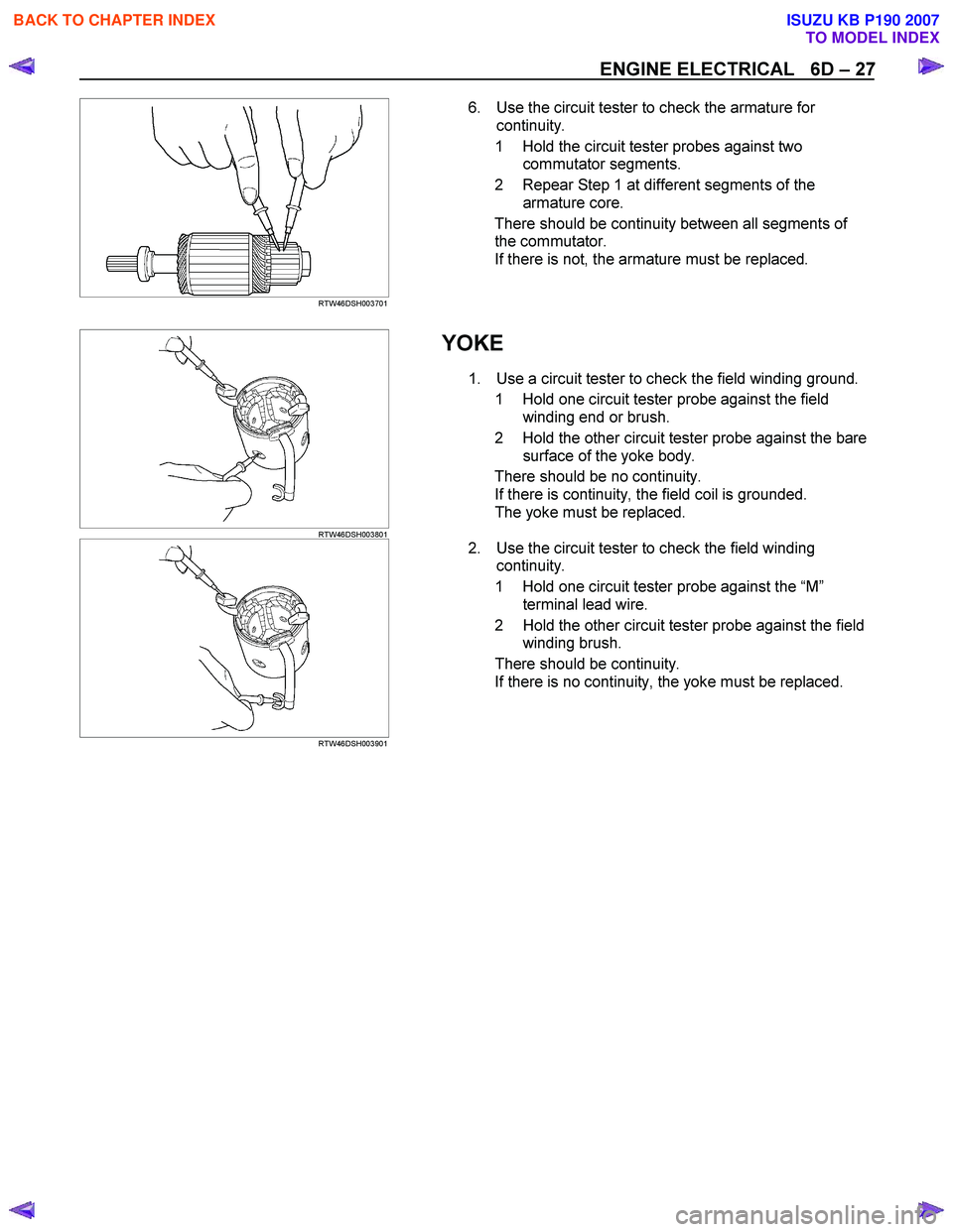
6. Use the circuit tester to check the armature for
continuity.
1 Hold the circuit tester probes against two commutator segments.
2 Repear Step 1 at different segments of the armature core.
There should be continuity between all segments of the commutator.
If there is not, the armature must be replaced.
RTW46DSH003801
YOKE
1. Use a circuit tester to check the field winding ground.
1 Hold one circuit tester probe against the field winding end or brush.
2 Hold the other circuit tester probe against the bare surface of the yoke body.
There should be no continuity. If there is continuity, the field coil is grounded.
The yoke must be replaced.
RTW46DSH003901
2. Use the circuit tester to check the field winding
continuity.
1 Hold one circuit tester probe against the “M ”
terminal lead wire.
2 Hold the other circuit tester probe against the field winding brush.
There should be continuity. If there is no continuity, the yoke must be replaced.
BACK TO CHAPTER INDEX
TO MODEL INDEX
ISUZU KB P190 2007
Page 1033 of 6020
6D – 32 ENGINE ELECTRICAL
MAGNETIC SWITCH
The following tests must be performed with the starter
motor fully assembled.
The yoke lead wire must be disconnected from the “M ”
terminal.
To prevent coil burning, complete each test as quickly as
possible (within three to five seconds).
RTW46DSH004601
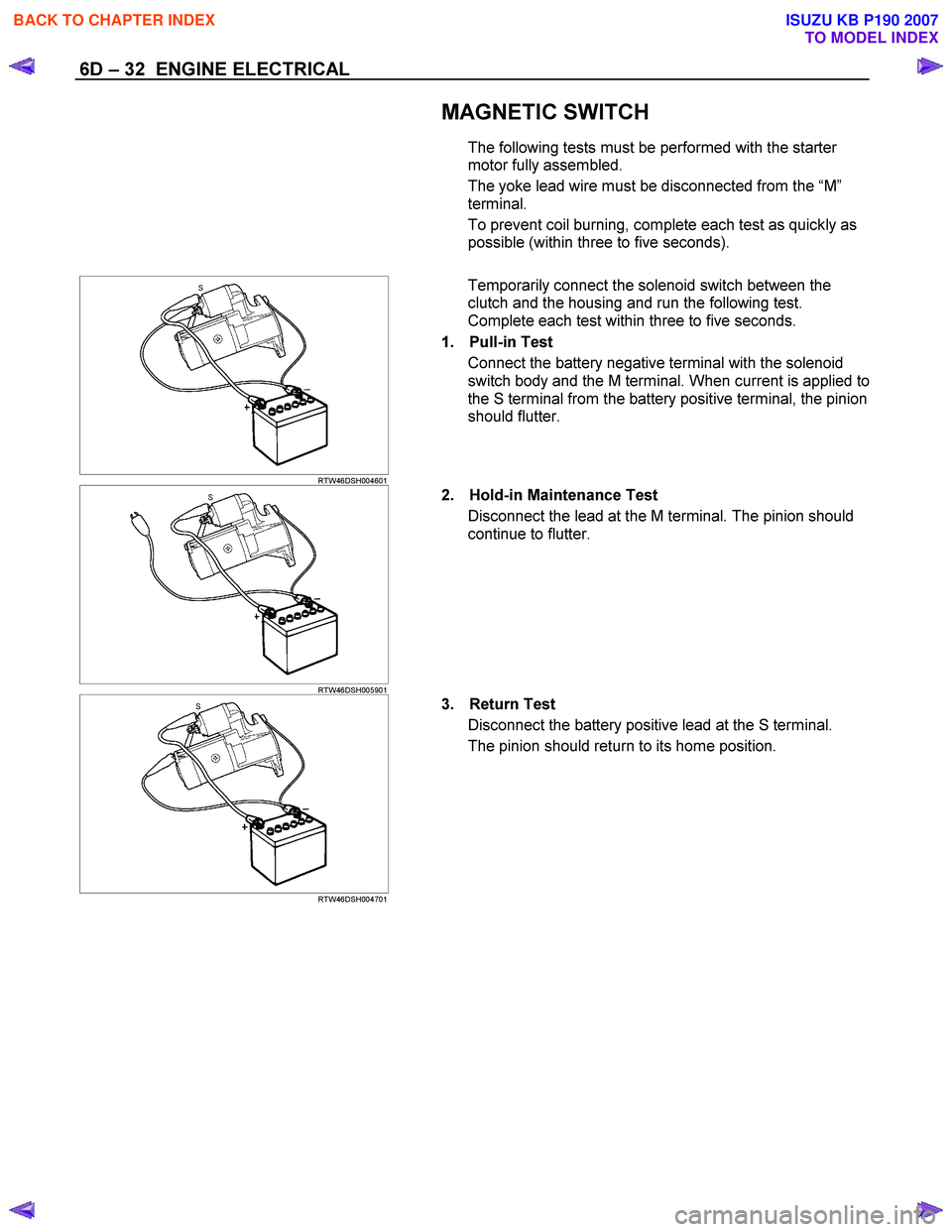
Temporarily connect the solenoid switch between the
clutch and the housing and run the following test.
Complete each test within three to five seconds.
1. Pull-in Test Connect the battery negative terminal with the solenoid
switch body and the M terminal. When current is applied to
the S terminal from the battery positive terminal, the pinion
should flutter.
RTW46DSH005901
2. Hold-in Maintenance Test
Disconnect the lead at the M terminal. The pinion should
continue to flutter.
RTW46DSH004701
3. Return Test
Disconnect the battery positive lead at the S terminal.
The pinion should return to its home position.
BACK TO CHAPTER INDEX
TO MODEL INDEX
ISUZU KB P190 2007
Page 1082 of 6020
6E-48 Engine Control System (4JH1)
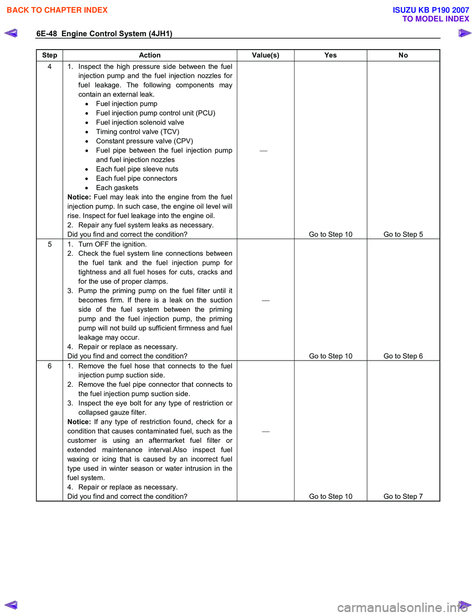
Step Action Value(s) Yes No
4 1. Inspect the high pressure side between the fuel
injection pump and the fuel injection nozzles for
fuel leakage. The following components may
contain an external leak. • Fuel injection pump
• Fuel injection pump control unit (PCU)
• Fuel injection solenoid valve
• Timing control valve (TCV)
• Constant pressure valve (CPV)
• Fuel pipe between the fuel injection pump
and fuel injection nozzles
• Each fuel pipe sleeve nuts
• Each fuel pipe connectors
• Each gaskets
Notice: Fuel may leak into the engine from the fuel
injection pump. In such case, the engine oil level will
rise. Inspect for fuel leakage into the engine oil.
2. Repair any fuel system leaks as necessary.
Did you find and correct the condition?
Go to Step 10 Go to Step 5
5 1. Turn OFF the ignition. 2. Check the fuel system line connections between the fuel tank and the fuel injection pump for
tightness and all fuel hoses for cuts, cracks and
for the use of proper clamps.
3. Pump the priming pump on the fuel filter until it becomes firm. If there is a leak on the suction
side of the fuel system between the priming
pump and the fuel injection pump, the priming
pump will not build up sufficient firmness and fuel
leakage may occur.
4. Repair or replace as necessary.
Did you find and correct the condition?
Go to Step 10 Go to Step 6
6 1. Remove the fuel hose that connects to the fuel injection pump suction side.
2. Remove the fuel pipe connector that connects to the fuel injection pump suction side.
3. Inspect the eye bolt for any type of restriction or collapsed gauze filter.
Notice: If any type of restriction found, check for a
condition that causes contaminated fuel, such as the
customer is using an aftermarket fuel filter or
extended maintenance interval.Also inspect fuel
waxing or icing that is caused by an incorrect fuel
type used in winter season or water intrusion in the
fuel system.
4. Repair or replace as necessary.
Did you find and correct the condition?
Go to Step 10 Go to Step 7
BACK TO CHAPTER INDEX
TO MODEL INDEX
ISUZU KB P190 2007
Page 1090 of 6020
6E-56 Engine Control System (4JH1)
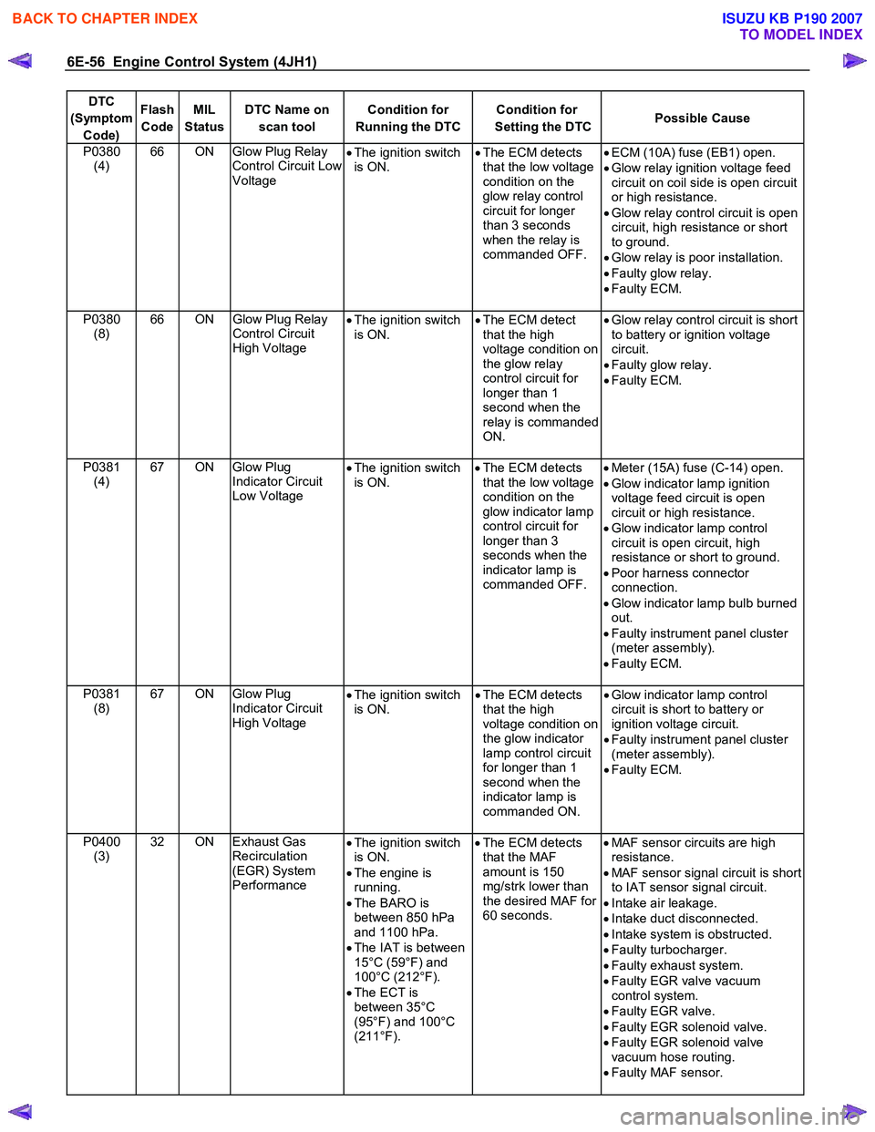
DTC
(Symptom Code) Flash
Code MIL
Status DTC Name on
scan tool Condition for
Running the DTC Condition for
Setting the DTC Possible Cause
P0380
(4) 66 ON Glow Plug Relay
Control Circuit Low
Voltage •
The ignition switch
is ON. •
The ECM detects
that the low voltage
condition on the
glow relay control
circuit for longer
than 3 seconds
when the relay is
commanded OFF.
•
ECM (10A) fuse (EB1) open.
• Glow relay ignition voltage feed
circuit on coil side is open circuit
or high resistance.
• Glow relay control circuit is open
circuit, high resistance or short
to ground.
• Glow relay is poor installation.
• Faulty glow relay.
• Faulty ECM.
P0380 (8) 66 ON
Glow Plug Relay
Control Circuit
High Voltage •
The ignition switch
is ON. •
The ECM detect
that the high
voltage condition on
the glow relay
control circuit for
longer than 1
second when the
relay is commanded
ON.
•
Glow relay control circuit is short
to battery or ignition voltage
circuit.
• Faulty glow relay.
• Faulty ECM.
P0381 (4) 67 ON Glow Plug
Indicator Circuit
Low Voltage •
The ignition switch
is ON.
•
The ECM detects
that the low voltage
condition on the
glow indicator lamp
control circuit for
longer than 3
seconds when the
indicator lamp is
commanded OFF.
•
Meter (15A) fuse (C-14) open.
• Glow indicator lamp ignition
voltage feed circuit is open
circuit or high resistance.
• Glow indicator lamp control
circuit is open circuit, high
resistance or short to ground.
• Poor harness connector
connection.
• Glow indicator lamp bulb burned
out.
• Faulty instrument panel cluster
(meter assembly).
• Faulty ECM.
P0381 (8) 67 ON Glow Plug
Indicator Circuit
High Voltage •
The ignition switch
is ON. •
The ECM detects
that the high
voltage condition on
the glow indicator
lamp control circuit
for longer than 1
second when the
indicator lamp is
commanded ON.
•
Glow indicator lamp control
circuit is short to battery or
ignition voltage circuit.
• Faulty instrument panel cluster
(meter assembly).
• Faulty ECM.
P0400 (3) 32 ON Exhaust Gas
Recirculation
(EGR) System
Performance •
The ignition switch
is ON.
• The engine is
running.
• The BARO is
between 850 hPa
and 1100 hPa.
• The IAT is between
15°C (59°F) and
100°C (212°F).
• The ECT is
between 35°C
(95°F) and 100°C
(211°F).
•
The ECM detects
that the MAF
amount is 150
mg/strk lower than
the desired MAF for
60 seconds.
•
MAF sensor circuits are high
resistance.
• MAF sensor signal circuit is short
to IAT sensor signal circuit.
• Intake air leakage.
• Intake duct disconnected.
• Intake system is obstructed.
• Faulty turbocharger.
• Faulty exhaust system.
• Faulty EGR valve vacuum
control system.
• Faulty EGR valve.
• Faulty EGR solenoid valve.
• Faulty EGR solenoid valve
vacuum hose routing.
• Faulty MAF sensor.
BACK TO CHAPTER INDEX
TO MODEL INDEX
ISUZU KB P190 2007
Page 1093 of 6020
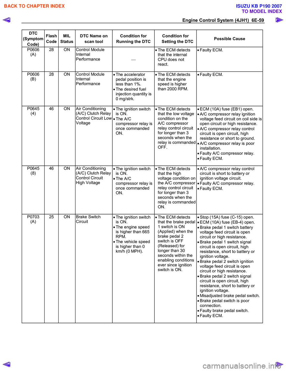
Engine Control System (4JH1) 6E-59
DTC
(Symptom Code) Flash
Code MIL
Status DTC Name on
scan tool Condition for
Running the DTC Condition for
Setting the DTC Possible Cause
P0606
(A) 28 ON Control Module
Internal
Performance
•
The ECM detects
that the internal
CPU does not
react.
•
Faulty ECM.
P0606
(B) 28 ON Control Module
Internal
Performance •
The accelerator
pedal position is
less than 1%.
• The desired fuel
injection quantity is
0 mg/strk.
•
The ECM detects
that the engine
speed is higher
than 2000 RPM. •
Faulty ECM.
P0645
(4) 46 ON Air Conditioning
(A/C) Clutch Relay
Control Circuit Low
Voltage •
The ignition switch
is ON.
• The A/C
compressor relay is
once commanded
ON. •
The ECM detects
that the low voltage
condition on the
A/C compressor
relay control circuit
for longer than 3
seconds when the
relay is commanded
OFF.
•
ECM (10A) fuse (EB1) open.
• A/C compressor relay ignition
voltage feed circuit on coil side is
open circuit or high resistance.
• A/C compressor relay control
circuit is open circuit, high
resistance or short to ground.
• A/C compressor relay is poor
installation.
• Faulty A/C compressor relay.
• Faulty ECM.
P0645 (8) 46 ON Air Conditioning
(A/C) Clutch Relay
Control Circuit
High Voltage •
The ignition switch
is ON.
• The A/C
compressor relay is
once commanded
ON. •
The ECM detects
that the high
voltage condition on
the A/C compressor
relay control circuit
for longer than 3
seconds when the
relay is commanded
ON.
•
A/C compressor relay control
circuit is short to battery or
ignition voltage circuit.
• Faulty A/C compressor relay.
• Faulty ECM.
P0703 (A) 25 ON Brake Switch
Circuit •
The ignition switch
is ON.
• The engine speed
is higher than 665
RPM.
• The vehicle speed
is higher than 0
km/h (0 MPH).
•
The ECM detects
that the brake pedal
1 switch is ON
(Applied) when the
brake pedal 2
switch is OFF
(Released) for
longer than 30
seconds within the
enabling conditions
ever since ignition
switch is ON. •
Stop (15A) fuse (C-15) open.
• ECM (10A) fuse (EB-4) open.
• Brake pedal 1 switch battery
voltage feed circuit is open
circuit or high resistance.
• Brake pedal 1 switch signal
circuit is open circuit, high
resistance, short to battery or
ignition voltage.
• Brake pedal 2 switch ignition
voltage feed circuit is open
circuit or high resistance.
• Brake pedal 2 switch signal
circuit is open circuit, high
resistance, short to battery or
ignition voltage.
• Misadjusted brake pedal switch.
• Brake pedal switch is poor
connection.
• Faulty brake pedal switch.
• Faulty ECM.
BACK TO CHAPTER INDEX
TO MODEL INDEX
ISUZU KB P190 2007
Page 1097 of 6020
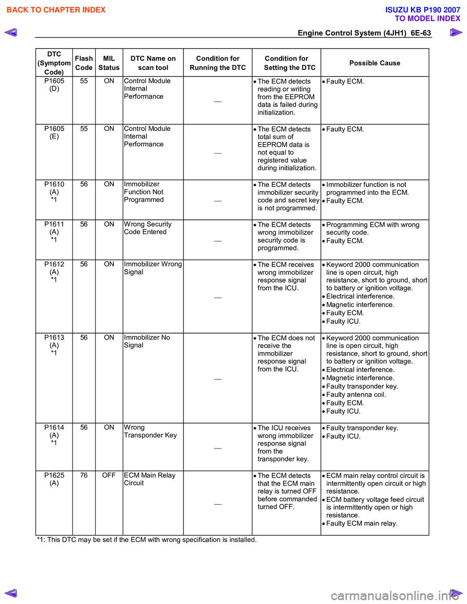
Engine Control System (4JH1) 6E-63
DTC
(Symptom Code) Flash
Code MIL
Status DTC Name on
scan tool Condition for
Running the DTC Condition for
Setting the DTC Possible Cause
P1605
(D) 55 ON Control Module
Internal
Performance •
The ECM detects
reading or writing
from the EEPROM
data is failed during
initialization.
•
Faulty ECM.
P1605
(E) 55 ON Control Module
Internal
Performance
•
The ECM detects
total sum of
EEPROM data is
not equal to
registered value
during initialization.
•
Faulty ECM.
P1610
(A) *1 56 ON Immobilizer
Function Not
Programmed •
The ECM detects
immobilizer security
code and secret key
is not programmed.
•
Immobilizer function is not
programmed into the ECM.
• Faulty ECM.
P1611 (A) *1 56 ON W rong Security
Code Entered
•
The ECM detects
wrong immobilizer
security code is
programmed.
•
Programming ECM with wrong
security code.
• Faulty ECM.
P1612 (A) *1 56 ON Immobilizer W rong
Signal
•
The ECM receives
wrong immobilizer
response signal
from the ICU.
•
Keyword 2000 communication
line is open circuit, high
resistance, short to ground, short
to battery or ignition voltage.
• Electrical interference.
• Magnetic interference.
• Faulty ECM.
• Faulty ICU.
P1613 (A) *1 56 ON Immobilizer No
Signal
•
The ECM does not
receive the
immobilizer
response signal
from the ICU.
•
Keyword 2000 communication
line is open circuit, high
resistance, short to ground, short
to battery or ignition voltage.
• Electrical interference.
• Magnetic interference.
• Faulty transponder key.
• Faulty antenna coil.
• Faulty ECM.
• Faulty ICU.
P1614 (A) *1 56 ON W rong
Transponder Key
•
The ICU receives
wrong immobilizer
response signal
from the
transponder key.
•
Faulty transponder key.
• Faulty ICU.
P1625 (A) 76 OFF ECM Main Relay
Circuit
•
The ECM detects
that the ECM main
relay is turned OFF
before commanded
turned OFF.
•
ECM main relay control circuit is
intermittently open circuit or high
resistance.
• ECM battery voltage feed circuit
is intermittently open or high
resistance.
• Faulty ECM main relay.
*1: This DTC may be set if the ECM with wrong specification is installed.
BACK TO CHAPTER INDEX
TO MODEL INDEX
ISUZU KB P190 2007
Page 1153 of 6020
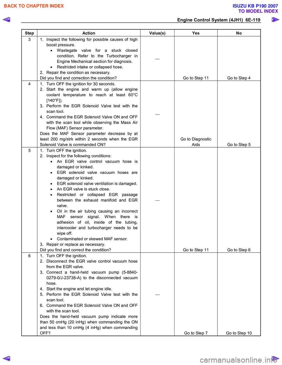
Engine Control System (4JH1) 6E-119
Step Action Value(s) Yes No
3 1. Inspect the following for possible causes of high
boost pressure. • W astegate valve for a stuck closed
condition. Refer to the Turbocharger in
Engine Mechanical section for diagnosis.
• Restricted intake or collapsed hose.
2. Repair the condition as necessary.
Did you find and correction the condition?
Go to Step 11 Go to Step 4
4 1. Turn OFF the ignition for 30 seconds. 2. Start the engine and warm up (allow engine coolant temperature to reach at least 60°C
[140°F]).
3. Perform the EGR Solenoid Valve test with the scan tool.
4. Command the EGR Solenoid Valve ON and OFF with the scan tool while observing the Mass Air
Flow (MAF) Sensor parameter.
Does the MAF Sensor parameter decrease by at
least 200 mg/strk within 2 seconds when the EGR
Solenoid Valve is commanded ON?
Go to Diagnostic Aids Go to Step 5
5 1. Turn OFF the ignition. 2. Inspect for the following conditions: • An EGR valve control vacuum hose is
damaged or kinked.
• EGR solenoid valve vacuum hoses are
damaged or kinked.
• EGR solenoid valve ventilation is damaged.
• An EGR valve is stuck close.
• Restricted or collapsed EGR passage
between the exhaust manifold and EGR
valve.
• Oil in the air tubing causing an incorrect
MAF sensor signal. W hen there is
adhesion of oil, inside of the tubing,
intercooler and turbocharger needs to be
wipe off.
• Contaminated or skewed MAF sensor.
3. Repair or replace as necessary.
Did you find and correct the condition?
Go to Step 11 Go to Step 6
6 1. Turn OFF the ignition. 2. Disconnect the EGR valve control vacuum hose from the EGR valve.
3. Connect a hand-held vacuum pump (5-8840- 0279-0/J-23738-A) to the disconnected vacuum
hose.
4. Start the engine and let engine idle.
5. Perform the EGR Solenoid Valve test with the scan tool.
6. Command the EGR Solenoid Valve ON and OFF with the scan tool.
Does the hand-held vacuum pump indicate more
than 50 cmHg (20 inHg) when commanding the ON
and less than 10 cmHg (4 inHg) when commanding
OFF?
Go to Step 7 Go to Step 10
BACK TO CHAPTER INDEX
TO MODEL INDEX
ISUZU KB P190 2007
Page 1164 of 6020
6E-130 Engine Control System (4JH1)
DTC P0335 (Symptom Code B, D) (Flash Code 43)
Circuit Description
The crankshaft position (CKP) sensor is located on top
of the flywheel housing. There are 4 slits spaced 90 °
on the flywheel circumference. The CKP sensor is a
magnetic coil type sensor, which generates an AC
signal voltage based on the crankshaft rotational speed.
The engine control module (ECM) monitors both the
CKP sensor and injection pump camshaft position
(CMP) sensor signals to ensure they correlate with each
other.
If the ECM receives extra or missing CKP sensor signal
pulses, this DTC will set. (Symptom Code B)
If the ECM receives a certain amount of injection pump
CMP sensor signal pulses without a CKP sensor signal,
this DTC will set. (Symptom Code D)
Condition for Running the DTC
Symptom Code B • The ignition switch is ON.
• The engine speed is higher than 665 RPM
Symptom Code D • DTC P0335 (Symptom Code B) is not set.
• The ignition switch is ON.
• The fuel injection pump CMP sensor signal is
generated.
• The controller area network (CAN) communication
between the ECM and PCU is normal.
Condition for Setting the DTC
Symptom Code B • The ECM detects extra or missing CKP senso
r
signals while engine is running.
Symptom Code D
• The ECM detects that the CKP sensor signals are
not generated when doubled fuel injection pump
rotation speed is higher than 50 RPM.
Action Taken When the DTC Sets
• The ECM illuminates the malfunction indicato
r
lamp (MIL) when the diagnostic runs and fails.
The ECM uses an engine speed substitution o
f
doubled fuel injection pump speed for engine
control.
Condition for Clearing the MIL/DTC
• The ECM turns OFF the MIL when the diagnostic
runs and does not fail.
• A history DTC clears after 40 consecutive driving
cycles without a fault. Or clear with the scan tool.
Diagnostic Aids
• If an intermittent condition is suspected, refer to
Intermittent Conditions in this section.
• Ensure the sensor is tight and the flywheel
circumference is not damaged.
DTC P0335 (Symptom Code B, D) (Flash Code 43)
Schematic Reference: Engine Controls Schematics
Connector End View Reference: Engine Controls
Connector End Views or Engine Control Module (ECM)
Connector End Views
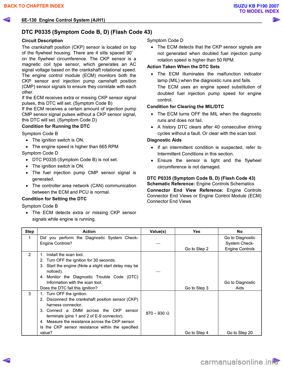
Step Action Value(s) Yes No
1 Did you perform the Diagnostic System Check-
Engine Controls?
Go to Step 2 Go to Diagnostic
System Check-
Engine Controls
2 1. Install the scan tool. 2. Turn OFF the ignition for 30 seconds.
3. Start the engine (Note a slight start delay may be noticed).
4. Monitor the Diagnostic Trouble Code (DTC) Information with the scan tool.
Does the DTC fail this ignition?
Go to Step 3 Go to Diagnostic
Aids
3 1. Turn OFF the ignition. 2. Disconnect the crankshaft position sensor (CKP) harness connector.
3. Connect a DMM across the CKP sensor terminals (pins 1 and 2 of E-9 connector).
4. Measure the resistance across the CKP sensor.
Is the CKP sensor resistance within the specified
value? 870 – 930
Ω
Go to Step 4 Go to Step 20
BACK TO CHAPTER INDEX
TO MODEL INDEX
ISUZU KB P190 2007