2007 ISUZU KB P190 BATTERY
[x] Cancel search: BATTERYPage 1165 of 6020
Engine Control System (4JH1) 6E-131
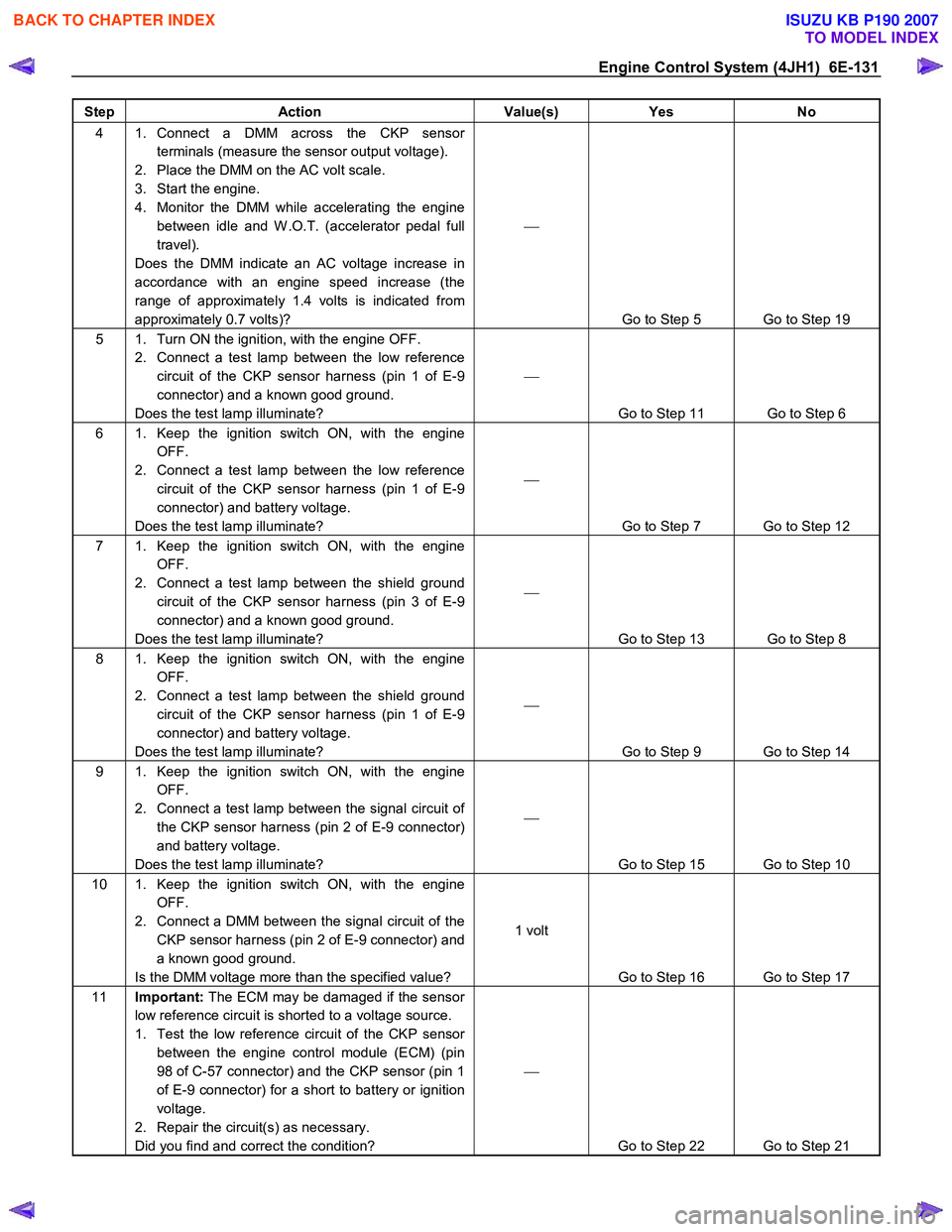
Step Action Value(s) Yes No
4 1. Connect a DMM across the CKP sensor
terminals (measure the sensor output voltage).
2. Place the DMM on the AC volt scale.
3. Start the engine.
4. Monitor the DMM while accelerating the engine between idle and W .O.T. (accelerator pedal full
travel).
Does the DMM indicate an AC voltage increase in
accordance with an engine speed increase (the
range of approximately 1.4 volts is indicated from
approximately 0.7 volts)?
Go to Step 5 Go to Step 19
5 1. Turn ON the ignition, with the engine OFF. 2. Connect a test lamp between the low reference circuit of the CKP sensor harness (pin 1 of E-9
connector) and a known good ground.
Does the test lamp illuminate?
Go to Step 11 Go to Step 6
6 1. Keep the ignition switch ON, with the engine OFF.
2. Connect a test lamp between the low reference circuit of the CKP sensor harness (pin 1 of E-9
connector) and battery voltage.
Does the test lamp illuminate?
Go to Step 7 Go to Step 12
7 1. Keep the ignition switch ON, with the engine OFF.
2. Connect a test lamp between the shield ground circuit of the CKP sensor harness (pin 3 of E-9
connector) and a known good ground.
Does the test lamp illuminate?
Go to Step 13 Go to Step 8
8 1. Keep the ignition switch ON, with the engine OFF.
2. Connect a test lamp between the shield ground circuit of the CKP sensor harness (pin 1 of E-9
connector) and battery voltage.
Does the test lamp illuminate?
Go to Step 9 Go to Step 14
9 1. Keep the ignition switch ON, with the engine OFF.
2. Connect a test lamp between the signal circuit of the CKP sensor harness (pin 2 of E-9 connector)
and battery voltage.
Does the test lamp illuminate?
Go to Step 15 Go to Step 10
10 1. Keep the ignition switch ON, with the engine OFF.
2. Connect a DMM between the signal circuit of the CKP sensor harness (pin 2 of E-9 connector) and
a known good ground.
Is the DMM voltage more than the specified value? 1 volt
Go to Step 16 Go to Step 17
11 Important: The ECM may be damaged if the sensor
low reference circuit is shorted to a voltage source.
1. Test the low reference circuit of the CKP sensor between the engine control module (ECM) (pin
98 of C-57 connector) and the CKP sensor (pin 1
of E-9 connector) for a short to battery or ignition
voltage.
2. Repair the circuit(s) as necessary.
Did you find and correct the condition?
Go to Step 22 Go to Step 21
BACK TO CHAPTER INDEX
TO MODEL INDEX
ISUZU KB P190 2007
Page 1166 of 6020
6E-132 Engine Control System (4JH1)
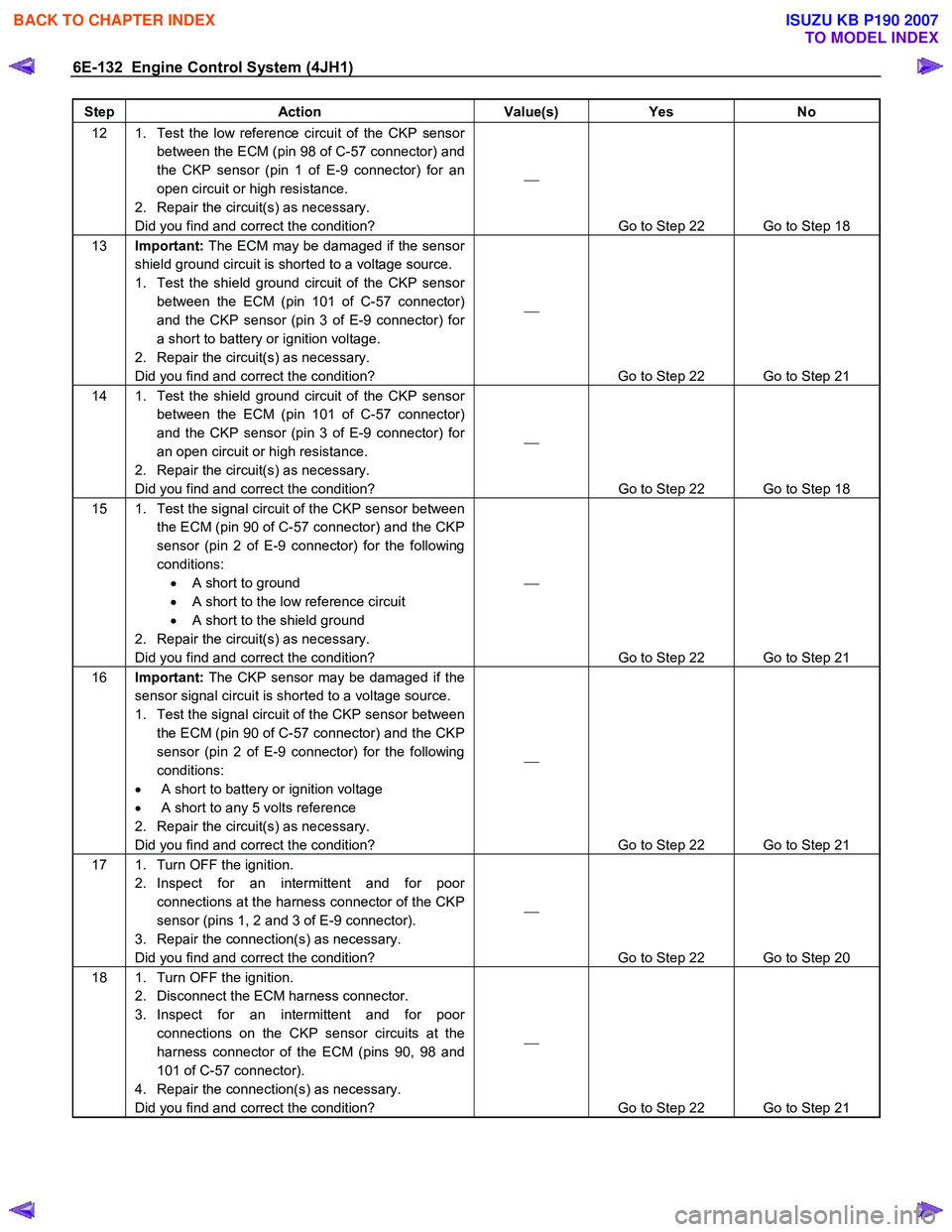
Step Action Value(s) Yes No
12 1. Test the low reference circuit of the CKP sensor
between the ECM (pin 98 of C-57 connector) and
the CKP sensor (pin 1 of E-9 connector) for an
open circuit or high resistance.
2. Repair the circuit(s) as necessary.
Did you find and correct the condition?
Go to Step 22 Go to Step 18
13 Important: The ECM may be damaged if the sensor
shield ground circuit is shorted to a voltage source.
1. Test the shield ground circuit of the CKP sensor between the ECM (pin 101 of C-57 connector)
and the CKP sensor (pin 3 of E-9 connector) for
a short to battery or ignition voltage.
2. Repair the circuit(s) as necessary.
Did you find and correct the condition?
Go to Step 22 Go to Step 21
14 1. Test the shield ground circuit of the CKP sensor between the ECM (pin 101 of C-57 connector)
and the CKP sensor (pin 3 of E-9 connector) for
an open circuit or high resistance.
2. Repair the circuit(s) as necessary.
Did you find and correct the condition?
Go to Step 22 Go to Step 18
15 1. Test the signal circuit of the CKP sensor between the ECM (pin 90 of C-57 connector) and the CKP
sensor (pin 2 of E-9 connector) for the following
conditions: • A short to ground
• A short to the low reference circuit
• A short to the shield ground
2. Repair the circuit(s) as necessary.
Did you find and correct the condition?
Go to Step 22 Go to Step 21
16 Important: The CKP sensor may be damaged if the
sensor signal circuit is shorted to a voltage source.
1. Test the signal circuit of the CKP sensor between the ECM (pin 90 of C-57 connector) and the CKP
sensor (pin 2 of E-9 connector) for the following
conditions:
• A short to battery or ignition voltage
• A short to any 5 volts reference
2. Repair the circuit(s) as necessary.
Did you find and correct the condition?
Go to Step 22 Go to Step 21
17 1. Turn OFF the ignition. 2. Inspect for an intermittent and for poor connections at the harness connector of the CKP
sensor (pins 1, 2 and 3 of E-9 connector).
3. Repair the connection(s) as necessary.
Did you find and correct the condition?
Go to Step 22 Go to Step 20
18 1. Turn OFF the ignition. 2. Disconnect the ECM harness connector.
3. Inspect for an intermittent and for poor connections on the CKP sensor circuits at the
harness connector of the ECM (pins 90, 98 and
101 of C-57 connector).
4. Repair the connection(s) as necessary.
Did you find and correct the condition?
Go to Step 22 Go to Step 21
BACK TO CHAPTER INDEX
TO MODEL INDEX
ISUZU KB P190 2007
Page 1171 of 6020
Engine Control System (4JH1) 6E-137
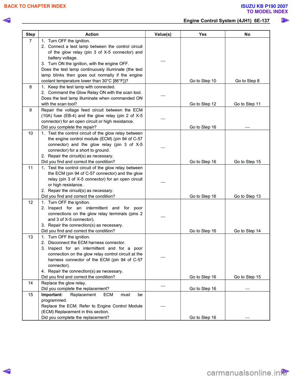
Step Action Value(s) Yes No
7 1. Turn OFF the ignition.
2. Connect a test lamp between the control circuit of the glow relay (pin 3 of X-5 connector) and
battery voltage.
3. Turn ON the ignition, with the engine OFF.
Does the test lamp continuously illuminate (the test
lamp blinks then goes out normally if the engine
coolant temperature lower than 30°C [86°F])?
Go to Step 10 Go to Step 8
8 1. Keep the test lamp with connected. 2. Command the Glow Relay ON with the scan tool.
Does the test lamp illuminate when commanded ON
with the scan tool?
Go to Step 12 Go to Step 11
9 Repair the voltage feed circuit between the ECM (10A) fuse (EB-4) and the glow relay (pin 2 of X-5
connector) for an open circuit or high resistance.
Did you complete the repair?
Go to Step 16
10 1. Test the control circuit of the glow relay between
the engine control module (ECM) (pin 94 of C-57
connector) and the glow relay (pin 3 of X-5
connector) for a short to ground.
2. Repair the circuit(s) as necessary.
Did you find and correct the condition?
Go to Step 16 Go to Step 15
11 1. Test the control circuit of the glow relay between the ECM (pin 94 of C-57 connector) and the glow
relay (pin 3 of X-5 connector) for an open circuit
or high resistance.
2. Repair the circuit(s) as necessary.
Did you find and correct the condition?
Go to Step 16 Go to Step 13
12 1. Turn OFF the ignition. 2. Inspect for an intermittent and for poor connections on the glow relay terminals (pins 2
and 3 of X-5 connector).
3. Repair the connection(s) as necessary.
Did you find and correct the condition?
Go to Step 16 Go to Step 14
13 1. Turn OFF the ignition. 2. Disconnect the ECM harness connector.
3. Inspect for an intermittent and for a poor connection on the glow relay control circuit at the
harness connector of the ECM (pin 94 of C-57
connector).
4. Repair the connection(s) as necessary.
Did you find and correct the condition?
Go to Step 16 Go to Step 15
14 Replace the glow relay. Did you complete the replacement?
Go to Step 16
15 Important: Replacement ECM must be
programmed.
Replace the ECM. Refer to Engine Control Module
(ECM) Replacement in this section.
Did you complete the replacement?
Go to Step 16
BACK TO CHAPTER INDEX
TO MODEL INDEX
ISUZU KB P190 2007
Page 1173 of 6020
Engine Control System (4JH1) 6E-139
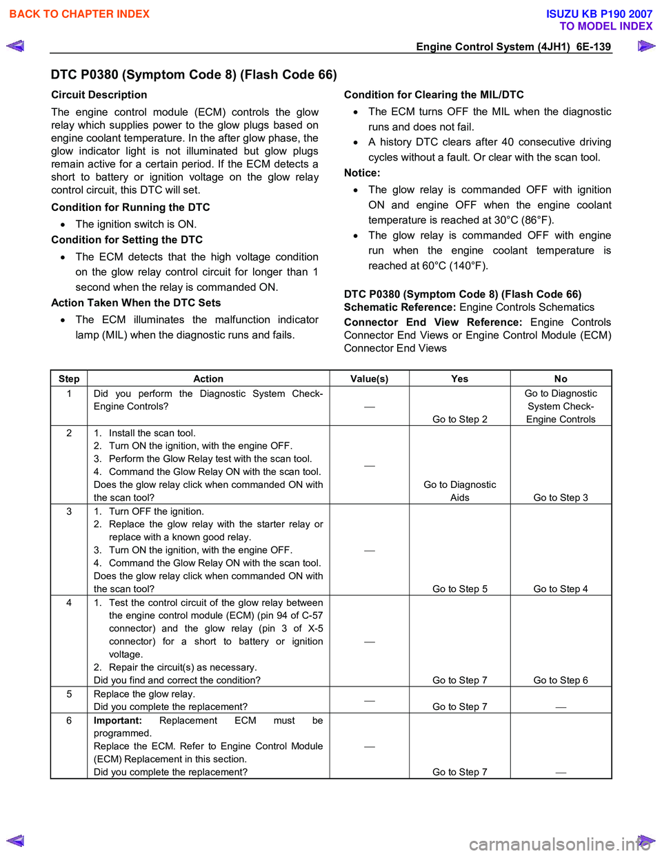
DTC P0380 (Symptom Code 8) (Flash Code 66)
Circuit Description
The engine control module (ECM) controls the glo
w
relay which supplies power to the glow plugs based on
engine coolant temperature. In the after glow phase, the
glow indicator light is not illuminated but glow plugs
remain active for a certain period. If the ECM detects a
short to battery or ignition voltage on the glow rela
y
control circuit, this DTC will set.
Condition for Running the DTC
• The ignition switch is ON.
Condition for Setting the DTC
• The ECM detects that the high voltage condition
on the glow relay control circuit for longer than 1
second when the relay is commanded ON.
Action Taken When the DTC Sets
• The ECM illuminates the malfunction indicato
r
lamp (MIL) when the diagnostic runs and fails.
Condition for Clearing the MIL/DTC
• The ECM turns OFF the MIL when the diagnostic
runs and does not fail.
• A history DTC clears after 40 consecutive driving
cycles without a fault. Or clear with the scan tool.
Notice:
• The glow relay is commanded OFF with ignition
ON and engine OFF when the engine coolant
temperature is reached at 30°C (86°F).
• The glow relay is commanded OFF with engine
run when the engine coolant temperature is
reached at 60°C (140°F).
DTC P0380 (Symptom Code 8) (Flash Code 66)
Schematic Reference: Engine Controls Schematics
Connector End View Reference: Engine Controls
Connector End Views or Engine Control Module (ECM)
Connector End Views
Step Action Value(s) Yes No
1 Did you perform the Diagnostic System Check-
Engine Controls?
Go to Step 2 Go to Diagnostic
System Check-
Engine Controls
2 1. Install the scan tool. 2. Turn ON the ignition, with the engine OFF.
3. Perform the Glow Relay test with the scan tool.
4. Command the Glow Relay ON with the scan tool.
Does the glow relay click when commanded ON with
the scan tool?
Go to Diagnostic Aids Go to Step 3
3 1. Turn OFF the ignition. 2. Replace the glow relay with the starter relay or replace with a known good relay.
3. Turn ON the ignition, with the engine OFF.
4. Command the Glow Relay ON with the scan tool.
Does the glow relay click when commanded ON with
the scan tool?
Go to Step 5 Go to Step 4
4 1. Test the control circuit of the glow relay between the engine control module (ECM) (pin 94 of C-57
connector) and the glow relay (pin 3 of X-5
connector) for a short to battery or ignition
voltage.
2. Repair the circuit(s) as necessary.
Did you find and correct the condition?
Go to Step 7 Go to Step 6
5 Replace the glow relay. Did you complete the replacement?
Go to Step 7
6 Important: Replacement ECM must be
programmed.
Replace the ECM. Refer to Engine Control Module
(ECM) Replacement in this section.
Did you complete the replacement?
Go to Step 7
BACK TO CHAPTER INDEX
TO MODEL INDEX
ISUZU KB P190 2007
Page 1178 of 6020
6E-144 Engine Control System (4JH1)
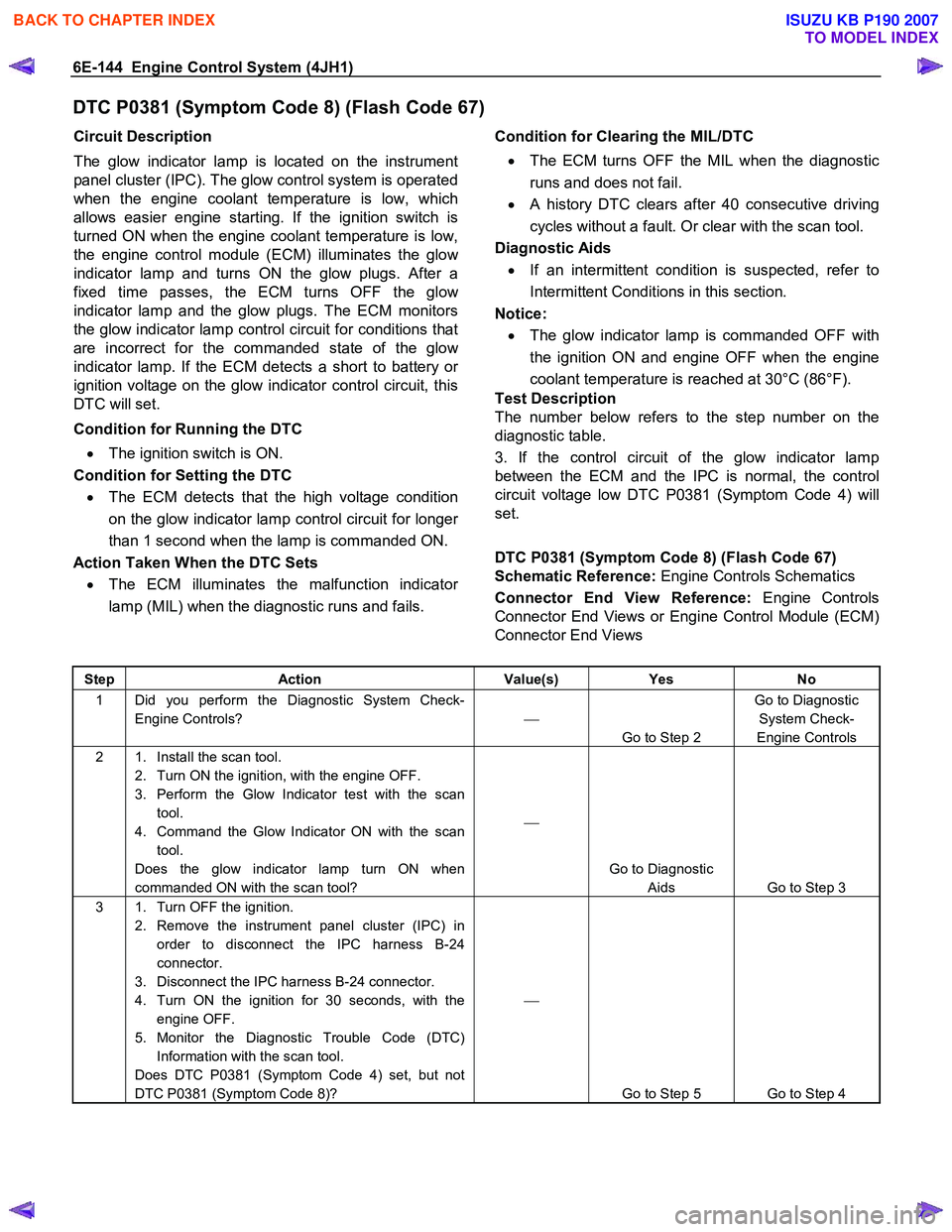
DTC P0381 (Symptom Code 8) (Flash Code 67)
Circuit Description
The glow indicator lamp is located on the instrument
panel cluster (IPC). The glow control system is operated
when the engine coolant temperature is low, which
allows easier engine starting. If the ignition switch is
turned ON when the engine coolant temperature is low,
the engine control module (ECM) illuminates the glo
w
indicator lamp and turns ON the glow plugs. After a
fixed time passes, the ECM turns OFF the glo
w
indicator lamp and the glow plugs. The ECM monitors
the glow indicator lamp control circuit for conditions that
are incorrect for the commanded state of the glo
w
indicator lamp. If the ECM detects a short to battery or
ignition voltage on the glow indicator control circuit, this
DTC will set.
Condition for Running the DTC • The ignition switch is ON.
Condition for Setting the DTC
• The ECM detects that the high voltage condition
on the glow indicator lamp control circuit for longe
r
than 1 second when the lamp is commanded ON.
Action Taken When the DTC Sets
• The ECM illuminates the malfunction indicato
r
lamp (MIL) when the diagnostic runs and fails.
Condition for Clearing the MIL/DTC
• The ECM turns OFF the MIL when the diagnostic
runs and does not fail.
• A history DTC clears after 40 consecutive driving
cycles without a fault. Or clear with the scan tool.
Diagnostic Aids
• If an intermittent condition is suspected, refer to
Intermittent Conditions in this section.
Notice:
• The glow indicator lamp is commanded OFF with
the ignition ON and engine OFF when the engine
coolant temperature is reached at 30°C (86°F).
Test Description
The number below refers to the step number on the
diagnostic table.
3. If the control circuit of the glow indicator lamp
between the ECM and the IPC is normal, the control
circuit voltage low DTC P0381 (Symptom Code 4) will
set.
DTC P0381 (Symptom Code 8) (Flash Code 67)
Schematic Reference: Engine Controls Schematics
Connector End View Reference: Engine Controls
Connector End Views or Engine Control Module (ECM)
Connector End Views
Step Action Value(s) Yes No
1 Did you perform the Diagnostic System Check-
Engine Controls?
Go to Step 2 Go to Diagnostic
System Check-
Engine Controls
2 1. Install the scan tool. 2. Turn ON the ignition, with the engine OFF.
3. Perform the Glow Indicator test with the scan tool.
4. Command the Glow Indicator ON with the scan tool.
Does the glow indicator lamp turn ON when
commanded ON with the scan tool?
Go to Diagnostic Aids Go to Step 3
3 1. Turn OFF the ignition. 2. Remove the instrument panel cluster (IPC) in order to disconnect the IPC harness B-24
connector.
3. Disconnect the IPC harness B-24 connector.
4. Turn ON the ignition for 30 seconds, with the engine OFF.
5. Monitor the Diagnostic Trouble Code (DTC) Information with the scan tool.
Does DTC P0381 (Symptom Code 4) set, but not
DTC P0381 (Symptom Code 8)?
Go to Step 5 Go to Step 4
BACK TO CHAPTER INDEX
TO MODEL INDEX
ISUZU KB P190 2007
Page 1179 of 6020
Engine Control System (4JH1) 6E-145
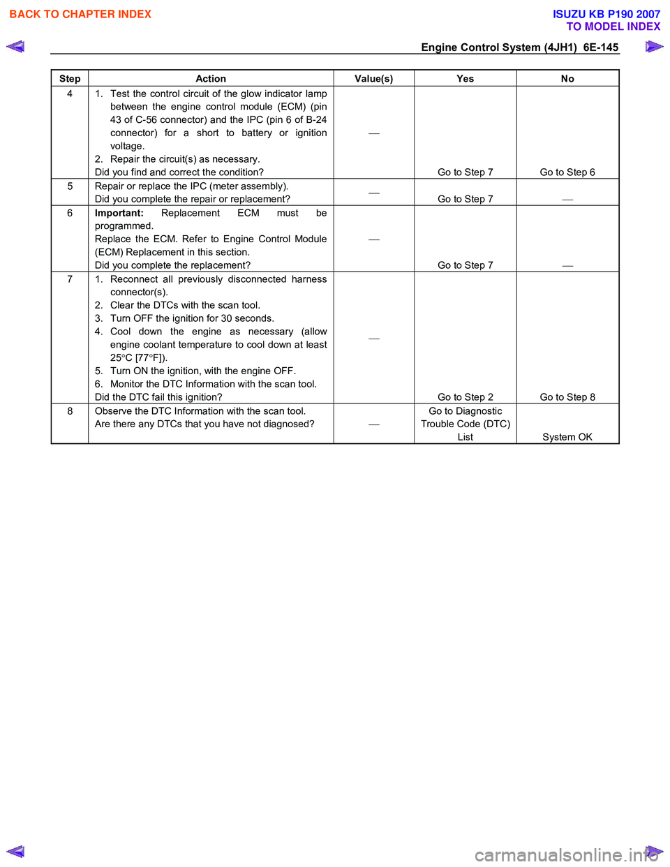
Step Action Value(s) Yes No
4 1. Test the control circuit of the glow indicator lamp
between the engine control module (ECM) (pin
43 of C-56 connector) and the IPC (pin 6 of B-24
connector) for a short to battery or ignition
voltage.
2. Repair the circuit(s) as necessary.
Did you find and correct the condition?
Go to Step 7 Go to Step 6
5 Repair or replace the IPC (meter assembly). Did you complete the repair or replacement?
Go to Step 7
6 Important: Replacement ECM must be
programmed.
Replace the ECM. Refer to Engine Control Module
(ECM) Replacement in this section.
Did you complete the replacement?
Go to Step 7
7 1. Reconnect all previously disconnected harness
connector(s).
2. Clear the DTCs with the scan tool.
3. Turn OFF the ignition for 30 seconds.
4. Cool down the engine as necessary (allow engine coolant temperature to cool down at least
25 °C [77 °F]).
5. Turn ON the ignition, with the engine OFF.
6. Monitor the DTC Information with the scan tool.
Did the DTC fail this ignition?
Go to Step 2 Go to Step 8
8 Observe the DTC Information with the scan tool. Are there any DTCs that you have not diagnosed? Go to Diagnostic
Trouble Code (DTC) List System OK
BACK TO CHAPTER INDEX
TO MODEL INDEX
ISUZU KB P190 2007
Page 1184 of 6020
6E-150 Engine Control System (4JH1)
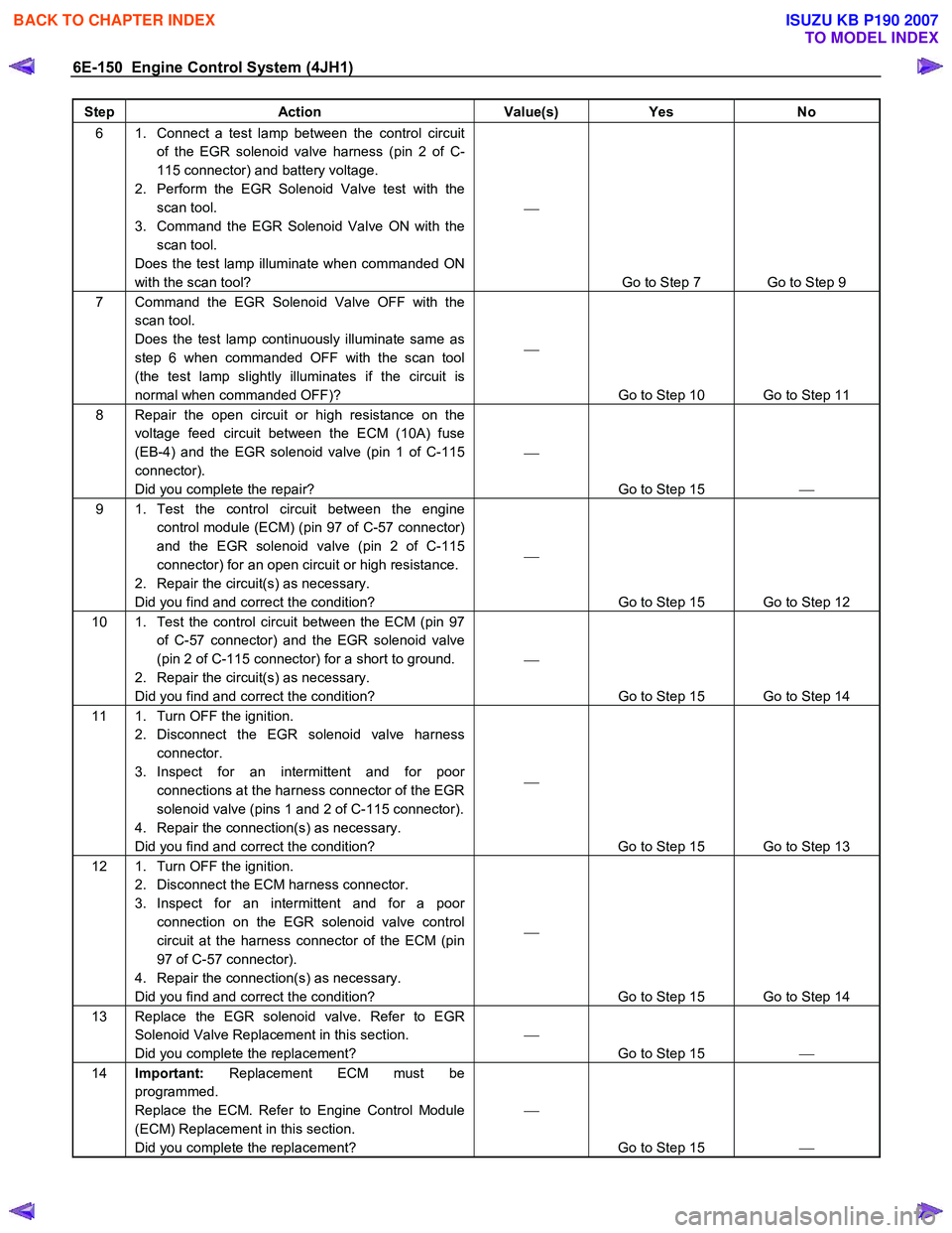
Step Action Value(s) Yes No
6 1. Connect a test lamp between the control circuit
of the EGR solenoid valve harness (pin 2 of C-
115 connector) and battery voltage.
2. Perform the EGR Solenoid Valve test with the scan tool.
3. Command the EGR Solenoid Valve ON with the scan tool.
Does the test lamp illuminate when commanded ON
with the scan tool?
Go to Step 7 Go to Step 9
7 Command the EGR Solenoid Valve OFF with the scan tool.
Does the test lamp continuously illuminate same as
step 6 when commanded OFF with the scan tool
(the test lamp slightly illuminates if the circuit is
normal when commanded OFF)?
Go to Step 10 Go to Step 11
8 Repair the open circuit or high resistance on the voltage feed circuit between the ECM (10A) fuse
(EB-4) and the EGR solenoid valve (pin 1 of C-115
connector).
Did you complete the repair?
Go to Step 15
9 1. Test the control circuit between the engine
control module (ECM) (pin 97 of C-57 connector)
and the EGR solenoid valve (pin 2 of C-115
connector) for an open circuit or high resistance.
2. Repair the circuit(s) as necessary.
Did you find and correct the condition?
Go to Step 15 Go to Step 12
10 1. Test the control circuit between the ECM (pin 97 of C-57 connector) and the EGR solenoid valve
(pin 2 of C-115 connector) for a short to ground.
2. Repair the circuit(s) as necessary.
Did you find and correct the condition?
Go to Step 15 Go to Step 14
11 1. Turn OFF the ignition. 2. Disconnect the EGR solenoid valve harness connector.
3. Inspect for an intermittent and for poor connections at the harness connector of the EGR
solenoid valve (pins 1 and 2 of C-115 connector).
4. Repair the connection(s) as necessary.
Did you find and correct the condition?
Go to Step 15 Go to Step 13
12 1. Turn OFF the ignition. 2. Disconnect the ECM harness connector.
3. Inspect for an intermittent and for a poor connection on the EGR solenoid valve control
circuit at the harness connector of the ECM (pin
97 of C-57 connector).
4. Repair the connection(s) as necessary.
Did you find and correct the condition?
Go to Step 15 Go to Step 14
13 Replace the EGR solenoid valve. Refer to EGR Solenoid Valve Replacement in this section.
Did you complete the replacement?
Go to Step 15
14 Important: Replacement ECM must be
programmed.
Replace the ECM. Refer to Engine Control Module
(ECM) Replacement in this section.
Did you complete the replacement?
Go to Step 15
BACK TO CHAPTER INDEX
TO MODEL INDEX
ISUZU KB P190 2007
Page 1189 of 6020
Engine Control System (4JH1) 6E-155
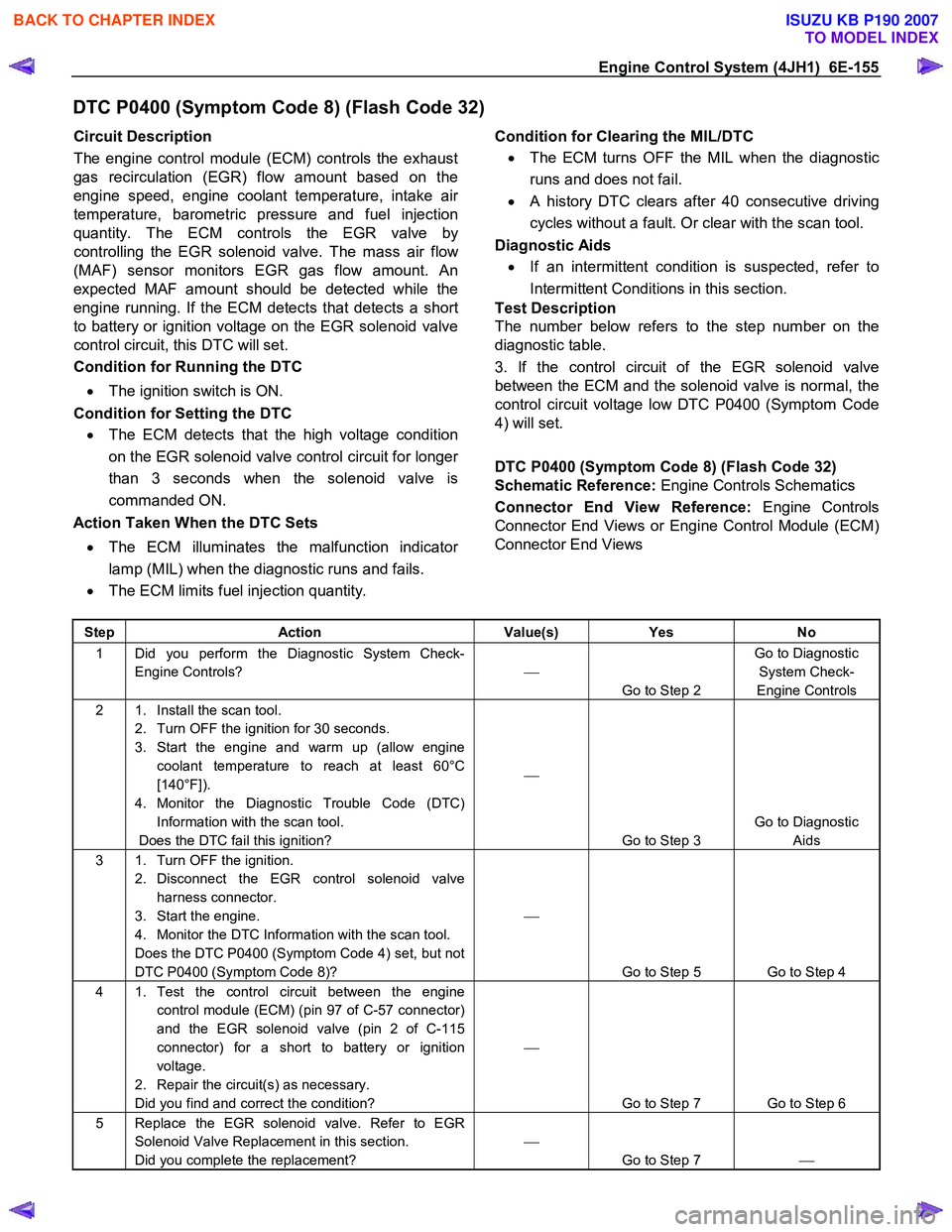
DTC P0400 (Symptom Code 8) (Flash Code 32)
Circuit Description
The engine control module (ECM) controls the exhaust
gas recirculation (EGR) flow amount based on the
engine speed, engine coolant temperature, intake ai
r
temperature, barometric pressure and fuel injection
quantity. The ECM controls the EGR valve by
controlling the EGR solenoid valve. The mass air flo
w
(MAF) sensor monitors EGR gas flow amount. An
expected MAF amount should be detected while the
engine running. If the ECM detects that detects a short
to battery or ignition voltage on the EGR solenoid valve
control circuit, this DTC will set.
Condition for Running the DTC
• The ignition switch is ON.
Condition for Setting the DTC • The ECM detects that the high voltage condition
on the EGR solenoid valve control circuit for longe
r
than 3 seconds when the solenoid valve is
commanded ON.
Action Taken When the DTC Sets
• The ECM illuminates the malfunction indicato
r
lamp (MIL) when the diagnostic runs and fails.
• The ECM limits fuel injection quantity.
Condition for Clearing the MIL/DTC
• The ECM turns OFF the MIL when the diagnostic
runs and does not fail.
• A history DTC clears after 40 consecutive driving
cycles without a fault. Or clear with the scan tool.
Diagnostic Aids
• If an intermittent condition is suspected, refer to
Intermittent Conditions in this section.
Test Description
The number below refers to the step number on the
diagnostic table.
3. If the control circuit of the EGR solenoid valve
between the ECM and the solenoid valve is normal, the
control circuit voltage low DTC P0400 (Symptom Code
4) will set.
DTC P0400 (Symptom Code 8) (Flash Code 32)
Schematic Reference: Engine Controls Schematics
Connector End View Reference: Engine Controls
Connector End Views or Engine Control Module (ECM)
Connector End Views
Step Action Value(s) Yes No
1 Did you perform the Diagnostic System Check-
Engine Controls?
Go to Step 2 Go to Diagnostic
System Check-
Engine Controls
2 1. Install the scan tool. 2. Turn OFF the ignition for 30 seconds.
3. Start the engine and warm up (allow engine coolant temperature to reach at least 60°C
[140°F]).
4. Monitor the Diagnostic Trouble Code (DTC) Information with the scan tool.
Does the DTC fail this ignition?
Go to Step 3 Go to Diagnostic
Aids
3 1. Turn OFF the ignition. 2. Disconnect the EGR control solenoid valve harness connector.
3. Start the engine.
4. Monitor the DTC Information with the scan tool.
Does the DTC P0400 (Symptom Code 4) set, but not
DTC P0400 (Symptom Code 8)?
Go to Step 5 Go to Step 4
4 1. Test the control circuit between the engine control module (ECM) (pin 97 of C-57 connector)
and the EGR solenoid valve (pin 2 of C-115
connector) for a short to battery or ignition
voltage.
2. Repair the circuit(s) as necessary.
Did you find and correct the condition?
Go to Step 7 Go to Step 6
5 Replace the EGR solenoid valve. Refer to EGR Solenoid Valve Replacement in this section.
Did you complete the replacement?
Go to Step 7
BACK TO CHAPTER INDEX
TO MODEL INDEX
ISUZU KB P190 2007