2007 ISUZU KB P190 BATTERY
[x] Cancel search: BATTERYPage 1242 of 6020
6E-208 Engine Control System (4JH1)
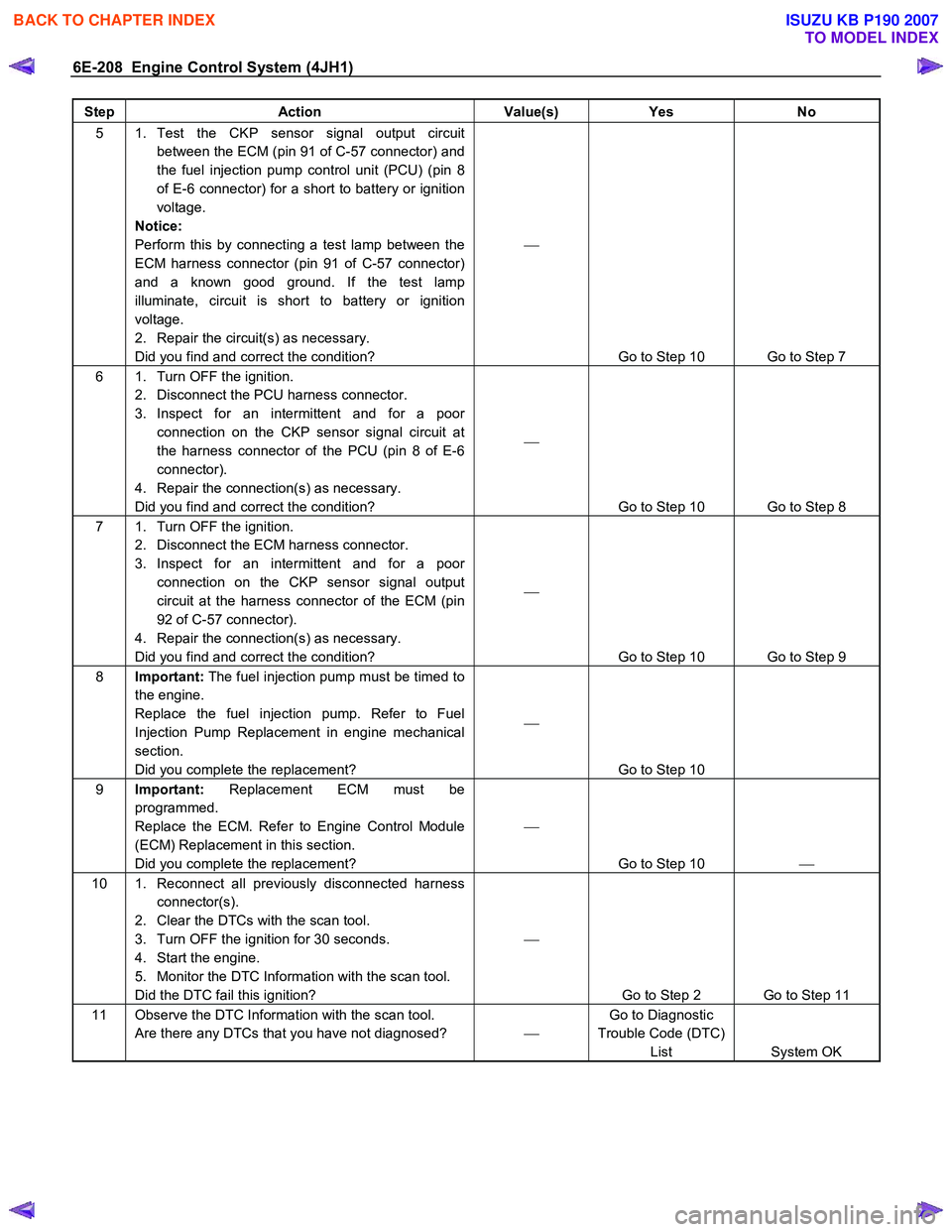
Step Action Value(s) Yes No
5 1. Test the CKP sensor signal output circuit
between the ECM (pin 91 of C-57 connector) and
the fuel injection pump control unit (PCU) (pin 8
of E-6 connector) for a short to battery or ignition
voltage.
Notice:
Perform this by connecting a test lamp between the
ECM harness connector (pin 91 of C-57 connector)
and a known good ground. If the test lamp
illuminate, circuit is short to battery or ignition
voltage.
2. Repair the circuit(s) as necessary.
Did you find and correct the condition?
Go to Step 10 Go to Step 7
6 1. Turn OFF the ignition. 2. Disconnect the PCU harness connector.
3. Inspect for an intermittent and for a poor connection on the CKP sensor signal circuit at
the harness connector of the PCU (pin 8 of E-6
connector).
4. Repair the connection(s) as necessary.
Did you find and correct the condition?
Go to Step 10 Go to Step 8
7 1. Turn OFF the ignition. 2. Disconnect the ECM harness connector.
3. Inspect for an intermittent and for a poor connection on the CKP sensor signal output
circuit at the harness connector of the ECM (pin
92 of C-57 connector).
4. Repair the connection(s) as necessary.
Did you find and correct the condition?
Go to Step 10 Go to Step 9
8 Important: The fuel injection pump must be timed to
the engine.
Replace the fuel injection pump. Refer to Fuel
Injection Pump Replacement in engine mechanical
section.
Did you complete the replacement?
Go to Step 10
9 Important: Replacement ECM must be
programmed.
Replace the ECM. Refer to Engine Control Module
(ECM) Replacement in this section.
Did you complete the replacement?
Go to Step 10
10 1. Reconnect all previously disconnected harness
connector(s).
2. Clear the DTCs with the scan tool.
3. Turn OFF the ignition for 30 seconds.
4. Start the engine.
5. Monitor the DTC Information with the scan tool.
Did the DTC fail this ignition?
Go to Step 2 Go to Step 11
11 Observe the DTC Information with the scan tool. Are there any DTCs that you have not diagnosed? Go to Diagnostic
Trouble Code (DTC) List System OK
BACK TO CHAPTER INDEX
TO MODEL INDEX
ISUZU KB P190 2007
Page 1244 of 6020
6E-210 Engine Control System (4JH1)
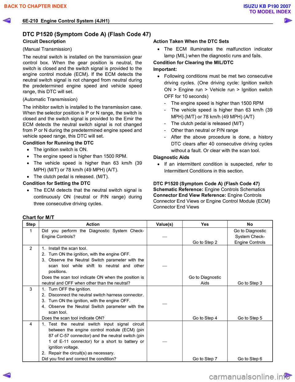
DTC P1520 (Symptom Code A) (Flash Code 47)
Circuit Description
(Manual Transmission)
The neutral switch is installed on the transmission gea
r
control box. W hen the gear position is neutral, the
switch is closed and the switch signal is provided to the
engine control module (ECM). If the ECM detects the
neutral switch signal is not changed from neutral during
the predetermined engine speed and vehicle speed
range, this DTC will set.
(Automatic Transmission)
The inhibitor switch is installed to the transmission case.
W hen the selector position is P or N range, the switch is
closed and the switch signal is provided to the Emir the
ECM detects the neutral switch signal is not changed
from P or N during the predetermined engine speed and
vehicle speed range, this DTC will set.
Condition for Running the DTC • The ignition switch is ON.
• The engine speed is higher than 1500 RPM.
• The vehicle speed is higher than 63 km/h (39
MPH) (M/T) or 78 km/h (49 MPH) (A/T).
• The clutch pedal is released. (M/T).
Condition for Setting the DTC
• The ECM detects that the neutral switch signal is
continuously ON (neutral or P/N range) during
three consecutive driving cycles.
Action Taken When the DTC Sets
• The ECM illuminates the malfunction indicato
r
lamp (MIL) when the diagnostic runs and fails.
Condition for Clearing the MIL/DTC
Important: • Following conditions must be met two consecutive
driving cycles. (One driving cycle: Ignition switch
ON > Engine run > Vehicle run > Ignition switch
OFF for 10 seconds)
- The engine speed is higher than 1500 RPM
- The vehicle speed is higher than 63 km/h (39 MPH) (M/T) or 78 km/h (49 MPH) (A/T)
- The clutch pedal is released (M/T)
- Other than neutral or P/N range
- After the above procedure is done, a history
DTC clears after 40 consecutive driving cycles
without a fault. Or clear with the scan tool.
Diagnostic Aids
• If an intermittent condition is suspected, refer to
Intermittent Conditions in this section.
DTC P1520 (Symptom Code A) (Flash Code 47)
Schematic Reference: Engine Controls Schematics
Connector End View Reference: Engine Controls
Connector End Views or Engine Control Module (ECM)
Connector End Views
Chart for M/T
Step Action Value(s) Yes No
1 Did you perform the Diagnostic System Check-
Engine Controls?
Go to Step 2 Go to Diagnostic
System Check-
Engine Controls
2 1. Install the scan tool. 2. Turn ON the ignition, with the engine OFF.
3. Observe the Neutral Switch parameter with the scan tool while shift to neutral and other
positions.
Does the scan tool indicate ON when the position is
neutral and OFF when other than the neutral?
Go to Diagnostic Aids Go to Step 3
3 1. Turn OFF the ignition. 2. Disconnect the neutral switch harness connector.
3. Turn ON the ignition, with the engine OFF.
4. Observe the Neutral Switch parameter with the scan tool.
Does the scan tool indicate ON?
Go to Step 4 Go to Step 5
4 1. Test the neutral switch input signal circuit between the engine control module (ECM) (pin
87 of C-57 connector) and the neutral switch (pin
1 of E-11 connector) for a short to battery or
ignition voltage.
2. Repair the circuit(s) as necessary.
Did you find and correct the condition?
Go to Step 7 Go to Step 6
BACK TO CHAPTER INDEX
TO MODEL INDEX
ISUZU KB P190 2007
Page 1246 of 6020
6E-212 Engine Control System (4JH1)
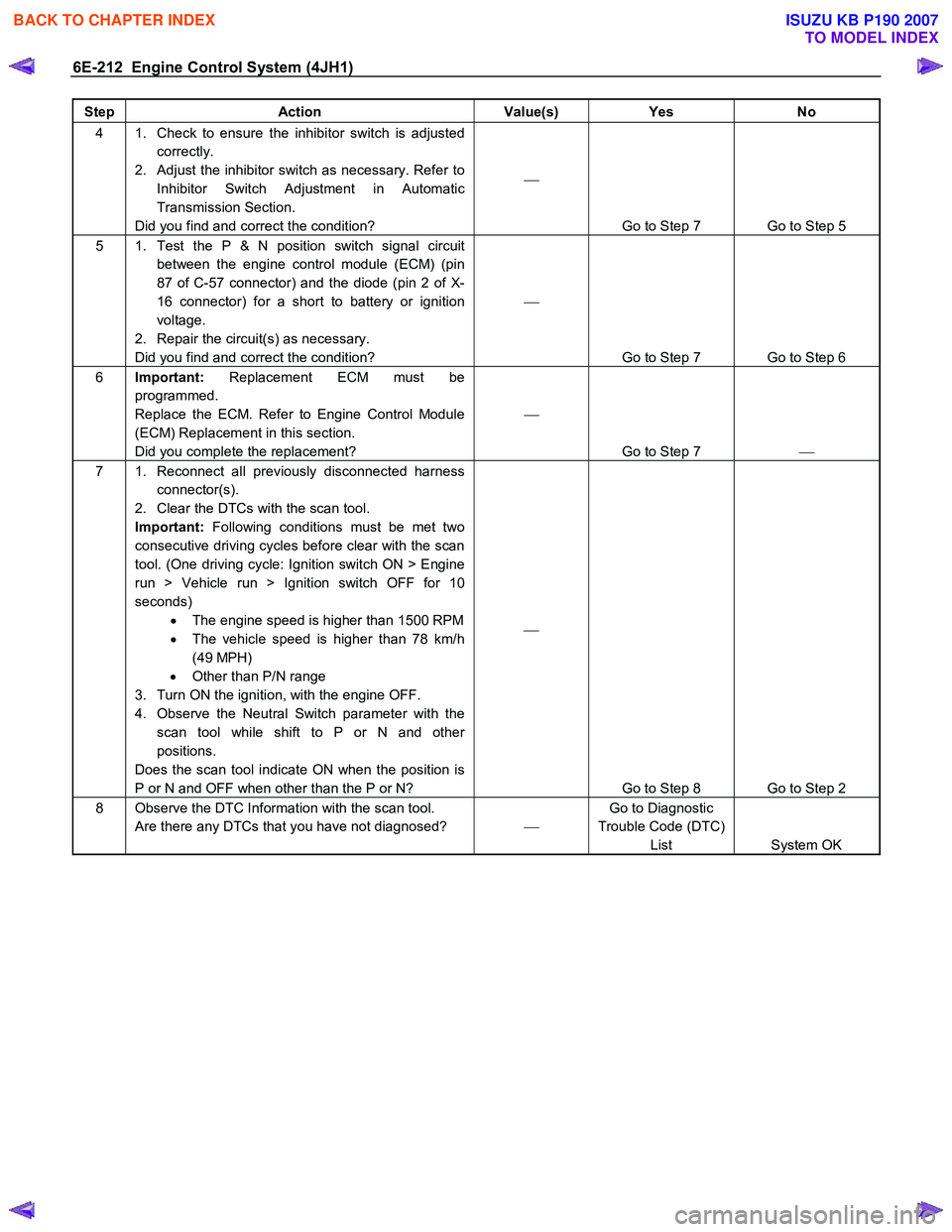
Step Action Value(s) Yes No
4 1. Check to ensure the inhibitor switch is adjusted
correctly.
2. Adjust the inhibitor switch as necessary. Refer to Inhibitor Switch Adjustment in Automatic
Transmission Section.
Did you find and correct the condition?
Go to Step 7 Go to Step 5
5 1. Test the P & N position switch signal circuit between the engine control module (ECM) (pin
87 of C-57 connector) and the diode (pin 2 of X-
16 connector) for a short to battery or ignition
voltage.
2. Repair the circuit(s) as necessary.
Did you find and correct the condition?
Go to Step 7 Go to Step 6
6 Important: Replacement ECM must be
programmed.
Replace the ECM. Refer to Engine Control Module
(ECM) Replacement in this section.
Did you complete the replacement?
Go to Step 7
7 1. Reconnect all previously disconnected harness
connector(s).
2. Clear the DTCs with the scan tool.
Important: Following conditions must be met two
consecutive driving cycles before clear with the scan
tool. (One driving cycle: Ignition switch ON > Engine
run > Vehicle run > Ignition switch OFF for 10
seconds) • The engine speed is higher than 1500 RPM
• The vehicle speed is higher than 78 km/h
(49 MPH)
• Other than P/N range
3. Turn ON the ignition, with the engine OFF.
4. Observe the Neutral Switch parameter with the scan tool while shift to P or N and other
positions.
Does the scan tool indicate ON when the position is
P or N and OFF when other than the P or N?
Go to Step 8 Go to Step 2
8 Observe the DTC Information with the scan tool. Are there any DTCs that you have not diagnosed? Go to Diagnostic
Trouble Code (DTC) List System OK
BACK TO CHAPTER INDEX
TO MODEL INDEX
ISUZU KB P190 2007
Page 1256 of 6020
6E-222 Engine Control System (4JH1)
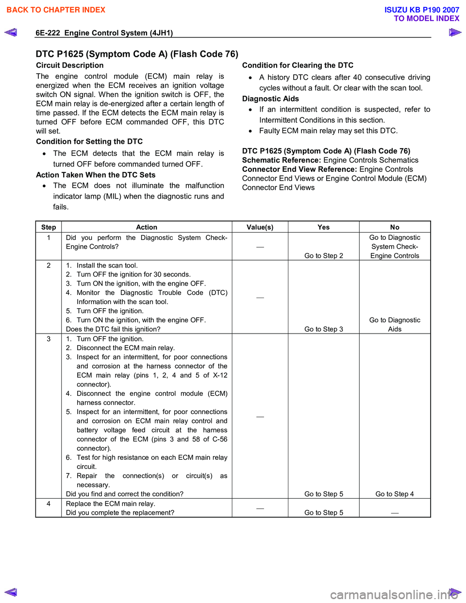
DTC P1625 (Symptom Code A) (Flash Code 76)
Circuit Description
The engine control module (ECM) main relay is
energized when the ECM receives an ignition voltage
switch ON signal. W hen the ignition switch is OFF, the
ECM main relay is de-energized after a certain length o
f
time passed. If the ECM detects the ECM main relay is
turned OFF before ECM commanded OFF, this DTC
will set.
Condition for Setting the DTC
• The ECM detects that the ECM main relay is
turned OFF before commanded turned OFF.
Action Taken When the DTC Sets • The ECM does not illuminate the malfunction
indicator lamp (MIL) when the diagnostic runs and
fails.
Condition for Clearing the DTC
• A history DTC clears after 40 consecutive driving
cycles without a fault. Or clear with the scan tool.
Diagnostic Aids
• If an intermittent condition is suspected, refer to
Intermittent Conditions in this section.
• Faulty ECM main relay may set this DTC.
DTC P1625 (Symptom Code A) (Flash Code 76)
Schematic Reference: Engine Controls Schematics
Connector End View Reference: Engine Controls
Connector End Views or Engine Control Module (ECM)
Connector End Views
Step Action Value(s) Yes No
1 Did you perform the Diagnostic System Check-
Engine Controls?
Go to Step 2 Go to Diagnostic
System Check-
Engine Controls
2 1. Install the scan tool. 2. Turn OFF the ignition for 30 seconds.
3. Turn ON the ignition, with the engine OFF.
4. Monitor the Diagnostic Trouble Code (DTC) Information with the scan tool.
5. Turn OFF the ignition.
6. Turn ON the ignition, with the engine OFF.
Does the DTC fail this ignition?
Go to Step 3 Go to Diagnostic
Aids
3 1. Turn OFF the ignition. 2. Disconnect the ECM main relay.
3. Inspect for an intermittent, for poor connections and corrosion at the harness connector of the
ECM main relay (pins 1, 2, 4 and 5 of X-12
connector).
4. Disconnect the engine control module (ECM) harness connector.
5. Inspect for an intermittent, for poor connections and corrosion on ECM main relay control and
battery voltage feed circuit at the harness
connector of the ECM (pins 3 and 58 of C-56
connector).
6. Test for high resistance on each ECM main relay circuit.
7. Repair the connection(s) or circuit(s) as necessary.
Did you find and correct the condition?
Go to Step 5 Go to Step 4
4 Replace the ECM main relay. Did you complete the replacement?
Go to Step 5
BACK TO CHAPTER INDEX
TO MODEL INDEX
ISUZU KB P190 2007
Page 1258 of 6020
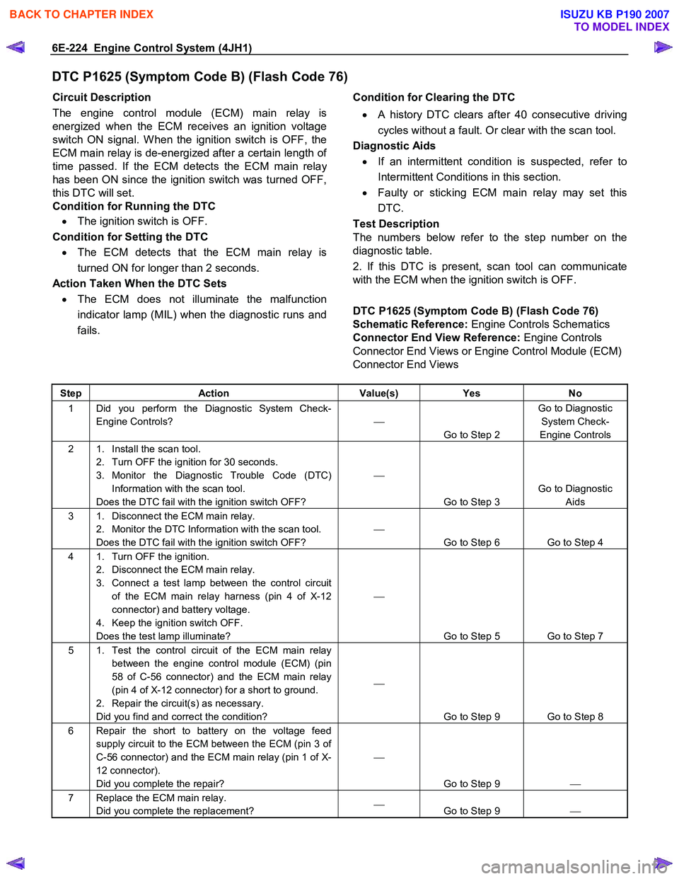
6E-224 Engine Control System (4JH1)
DTC P1625 (Symptom Code B) (Flash Code 76)
Circuit Description
The engine control module (ECM) main relay is
energized when the ECM receives an ignition voltage
switch ON signal. W hen the ignition switch is OFF, the
ECM main relay is de-energized after a certain length o
f
time passed. If the ECM detects the ECM main relay
has been ON since the ignition switch was turned OFF,
this DTC will set.
Condition for Running the DTC
• The ignition switch is OFF.
Condition for Setting the DTC • The ECM detects that the ECM main relay is
turned ON for longer than 2 seconds.
Action Taken When the DTC Sets • The ECM does not illuminate the malfunction
indicator lamp (MIL) when the diagnostic runs and
fails.
Condition for Clearing the DTC
• A history DTC clears after 40 consecutive driving
cycles without a fault. Or clear with the scan tool.
Diagnostic Aids
• If an intermittent condition is suspected, refer to
Intermittent Conditions in this section.
• Faulty or sticking ECM main relay may set this
DTC.
Test Description
The numbers below refer to the step number on the
diagnostic table.
2. If this DTC is present, scan tool can communicate
with the ECM when the ignition switch is OFF.
DTC P1625 (Symptom Code B) (Flash Code 76)
Schematic Reference: Engine Controls Schematics
Connector End View Reference: Engine Controls
Connector End Views or Engine Control Module (ECM)
Connector End Views
Step Action Value(s) Yes No
1 Did you perform the Diagnostic System Check-
Engine Controls?
Go to Step 2 Go to Diagnostic
System Check-
Engine Controls
2 1. Install the scan tool. 2. Turn OFF the ignition for 30 seconds.
3. Monitor the Diagnostic Trouble Code (DTC) Information with the scan tool.
Does the DTC fail with the ignition switch OFF?
Go to Step 3 Go to Diagnostic
Aids
3 1. Disconnect the ECM main relay. 2. Monitor the DTC Information with the scan tool.
Does the DTC fail with the ignition switch OFF?
Go to Step 6 Go to Step 4
4 1. Turn OFF the ignition. 2. Disconnect the ECM main relay.
3. Connect a test lamp between the control circuit of the ECM main relay harness (pin 4 of X-12
connector) and battery voltage.
4. Keep the ignition switch OFF.
Does the test lamp illuminate?
Go to Step 5 Go to Step 7
5 1. Test the control circuit of the ECM main relay between the engine control module (ECM) (pin
58 of C-56 connector) and the ECM main relay
(pin 4 of X-12 connector) for a short to ground.
2. Repair the circuit(s) as necessary.
Did you find and correct the condition?
Go to Step 9 Go to Step 8
6 Repair the short to battery on the voltage feed supply circuit to the ECM between the ECM (pin 3 of
C-56 connector) and the ECM main relay (pin 1 of X-
12 connector).
Did you complete the repair?
Go to Step 9
7 Replace the ECM main relay.
Did you complete the replacement?
Go to Step 9
BACK TO CHAPTER INDEX
TO MODEL INDEX
ISUZU KB P190 2007
Page 1262 of 6020
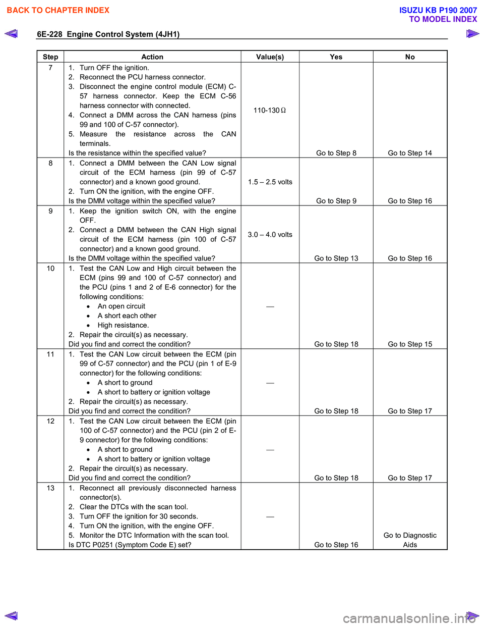
6E-228 Engine Control System (4JH1)
Step Action Value(s) Yes No
7 1. Turn OFF the ignition.
2. Reconnect the PCU harness connector.
3. Disconnect the engine control module (ECM) C- 57 harness connector. Keep the ECM C-56
harness connector with connected.
4. Connect a DMM across the CAN harness (pins 99 and 100 of C-57 connector).
5. Measure the resistance across the CAN terminals.
Is the resistance within the specified value? 110-130
Ω
Go to Step 8 Go to Step 14
8 1. Connect a DMM between the CAN Low signal circuit of the ECM harness (pin 99 of C-57
connector) and a known good ground.
2. Turn ON the ignition, with the engine OFF.
Is the DMM voltage within the specified value? 1.5 – 2.5 volts
Go to Step 9 Go to Step 16
9 1. Keep the ignition switch ON, with the engine OFF.
2. Connect a DMM between the CAN High signal circuit of the ECM harness (pin 100 of C-57
connector) and a known good ground.
Is the DMM voltage within the specified value? 3.0 – 4.0 volts
Go to Step 13 Go to Step 16
10 1. Test the CAN Low and High circuit between the ECM (pins 99 and 100 of C-57 connector) and
the PCU (pins 1 and 2 of E-6 connector) for the
following conditions: • An open circuit
• A short each other
• High resistance.
2. Repair the circuit(s) as necessary.
Did you find and correct the condition?
Go to Step 18 Go to Step 15
11 1. Test the CAN Low circuit between the ECM (pin 99 of C-57 connector) and the PCU (pin 1 of E-9
connector) for the following conditions: • A short to ground
• A short to battery or ignition voltage
2. Repair the circuit(s) as necessary.
Did you find and correct the condition?
Go to Step 18 Go to Step 17
12 1. Test the CAN Low circuit between the ECM (pin 100 of C-57 connector) and the PCU (pin 2 of E-
9 connector) for the following conditions: • A short to ground
• A short to battery or ignition voltage
2. Repair the circuit(s) as necessary.
Did you find and correct the condition?
Go to Step 18 Go to Step 17
13 1. Reconnect all previously disconnected harness connector(s).
2. Clear the DTCs with the scan tool.
3. Turn OFF the ignition for 30 seconds.
4. Turn ON the ignition, with the engine OFF.
5. Monitor the DTC Information with the scan tool.
Is DTC P0251 (Symptom Code E) set?
Go to Step 16 Go to Diagnostic
Aids
BACK TO CHAPTER INDEX
TO MODEL INDEX
ISUZU KB P190 2007
Page 1266 of 6020
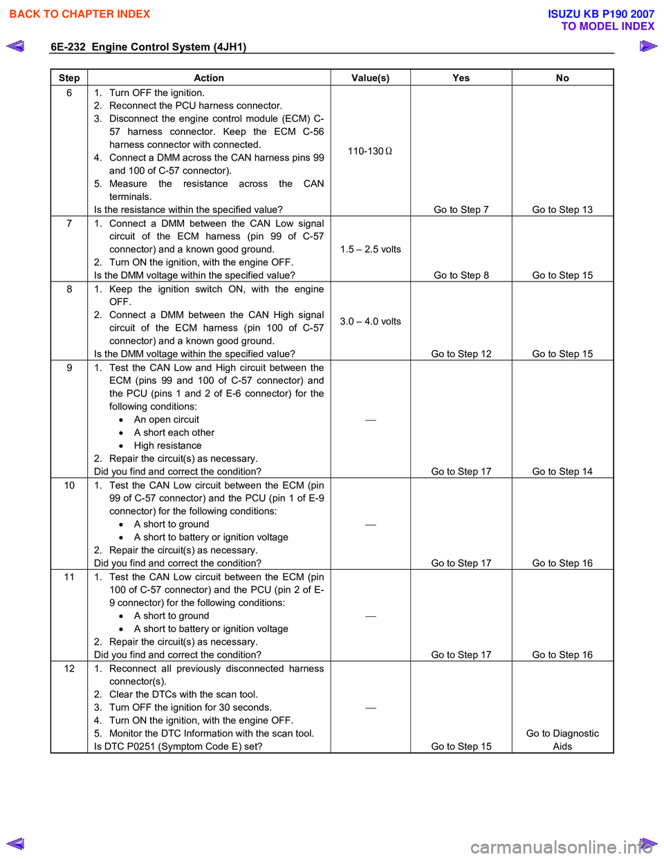
6E-232 Engine Control System (4JH1)
Step Action Value(s) Yes No
6 1. Turn OFF the ignition.
2. Reconnect the PCU harness connector.
3. Disconnect the engine control module (ECM) C- 57 harness connector. Keep the ECM C-56
harness connector with connected.
4. Connect a DMM across the CAN harness pins 99 and 100 of C-57 connector).
5. Measure the resistance across the CAN terminals.
Is the resistance within the specified value? 110-130
Ω
Go to Step 7 Go to Step 13
7 1. Connect a DMM between the CAN Low signal circuit of the ECM harness (pin 99 of C-57
connector) and a known good ground.
2. Turn ON the ignition, with the engine OFF.
Is the DMM voltage within the specified value? 1.5 – 2.5 volts
Go to Step 8 Go to Step 15
8 1. Keep the ignition switch ON, with the engine OFF.
2. Connect a DMM between the CAN High signal circuit of the ECM harness (pin 100 of C-57
connector) and a known good ground.
Is the DMM voltage within the specified value? 3.0 – 4.0 volts
Go to Step 12 Go to Step 15
9 1. Test the CAN Low and High circuit between the ECM (pins 99 and 100 of C-57 connector) and
the PCU (pins 1 and 2 of E-6 connector) for the
following conditions: • An open circuit
• A short each other
• High resistance
2. Repair the circuit(s) as necessary.
Did you find and correct the condition?
Go to Step 17 Go to Step 14
10 1. Test the CAN Low circuit between the ECM (pin 99 of C-57 connector) and the PCU (pin 1 of E-9
connector) for the following conditions: • A short to ground
• A short to battery or ignition voltage
2. Repair the circuit(s) as necessary.
Did you find and correct the condition?
Go to Step 17 Go to Step 16
11 1. Test the CAN Low circuit between the ECM (pin 100 of C-57 connector) and the PCU (pin 2 of E-
9 connector) for the following conditions: • A short to ground
• A short to battery or ignition voltage
2. Repair the circuit(s) as necessary.
Did you find and correct the condition?
Go to Step 17 Go to Step 16
12 1. Reconnect all previously disconnected harness connector(s).
2. Clear the DTCs with the scan tool.
3. Turn OFF the ignition for 30 seconds.
4. Turn ON the ignition, with the engine OFF.
5. Monitor the DTC Information with the scan tool.
Is DTC P0251 (Symptom Code E) set?
Go to Step 15 Go to Diagnostic
Aids
BACK TO CHAPTER INDEX
TO MODEL INDEX
ISUZU KB P190 2007
Page 1268 of 6020

6E-234 Engine Control System (4JH1)
DTC P1690 (Symptom Code 4) (Flash Code 77)
Circuit Description
The malfunction indicator lamp (MIL) is located on the
instrument panel cluster (IPC). The battery voltage is
supplied to the MIL. The engine control module (ECM)
turns the MIL ON by grounding the MIL control circuit.
After a fixed time passes, the ECM turns OFF the MIL
with the ignition ON and the engine OFF. The MIL has
the following functions:
• The MIL informs the driver that a malfunction has
occurred and the vehicle should be taken in fo
r
service as soon as possible.
• The MIL illuminates during a bulb test and a
system test.
•
A DTC will be stored if a MIL is requested by the
ECM.
If the ECM detects an open circuit or short circuit on the
MIL control circuit, this DTC will set.
Condition for Running the DTC • The ignition switch is ON.
Condition for Setting the DTC
• The ECM detects a low voltage condition on the
MIL control circuit for longer than 3 seconds when
the MIL is commanded OFF.
Action Taken When the DTC Sets • The ECM does not illuminates the MIL when the
diagnostic runs and fails.
Condition for Clearing the DTC • A history DTC clears after 40 consecutive driving
cycles without a fault. Or clear with the scan tool.
Diagnostic Aids
• If an intermittent condition is suspected, refer to
Intermittent Conditions in this section.
DTC P1690 (Symptom Code 4) (Flash Code 77)
Schematic Reference: Engine Controls Schematics
Connector End View Reference: Engine Controls
Connector End Views or Engine Control Module (ECM)
Connector End Views
Step Action Value(s) Yes No
1 Did you perform the Diagnostic System Check-
Engine Controls?
Go to Step 2 Go to Diagnostic
System Check-
Engine Controls
2 1. Install the scan tool. 2. Turn ON the ignition, with the engine OFF.
3. Perform the Malfunction Indicator Lamp (MIL) test with the scan tool.
4. Command the MIL ON with the scan tool.
Does the MIL turn ON when commanded ON with
the scan tool?
Go to Step 3 Go to Step 4
3 Command the MIL OFF with the scan tool. Does the MIL OFF?
Go to Step 17 Go to Step 10
4 1. Turn OFF the ignition.
2. Inspect the Meter (15A) fuse (C-14) in the cabin fuse block.
Is the Meter (15A) fuse (C-14) open?
Go to Step 5 Go to Step 6
5 Replace the Meter (15A) fuse (C-14). If the fuse continues to open, repair the short to ground on one
of the circuits that fed by the Meter (15A) fuse (C-14)
or replace the shorted attached component fed by
the Meter (15A) fuse (C-14).
Did you complete the repair?
Go to Step 19
6 1. Turn OFF the ignition.
2. Disconnect the engine control module (ECM) harness connector.
3. Turn ON the ignition, with the engine OFF.
4. Connect a 3-amp fused jumper wire between the MIL control circuit of the ECM harness connector
(pin 42 of C-56 connector) and a known good
ground.
Does the MIL illuminate?
Go to Step 11 Go to Step 7
BACK TO CHAPTER INDEX
TO MODEL INDEX
ISUZU KB P190 2007