2007 ISUZU KB P190 BATTERY
[x] Cancel search: BATTERYPage 1315 of 6020
Engine Control System (4JH1) 6E-281
Installation Procedure
1. Install the MAF & IAT sensor assembly into intake air duct.
2. Tighten the clips.
3. Connect a MAF & IAT sensor connector to the MAF & IAT sensor assembly.
4. Connect the negative battery cable.
Turbocharger Solenoid Valve Replacement
[High Altitude Spec]
Removal Procedure
1. Disconnect the negative battery cable.
2. Disconnect a harness connector from the turbocharger solenoid valve.
3. Disconnect two hoses from the turbocharge
r
solenoid valve.
4. Loosen a nut and remove the turbocharger solenoid valve from the bracket.
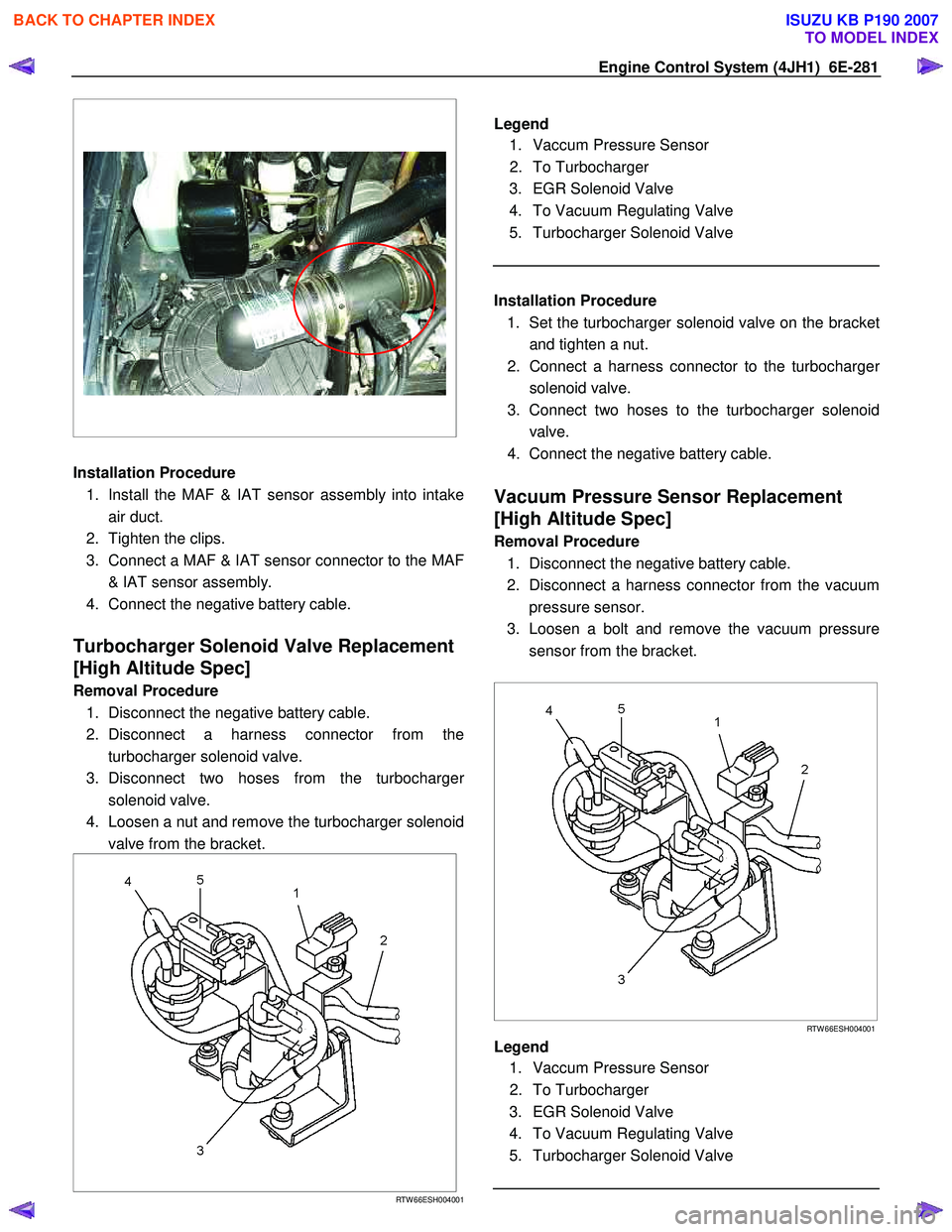
RTW 66ESH004001
Legend
1. Vaccum Pressure Sensor
2. To Turbocharger
3. EGR Solenoid Valve
4. To Vacuum Regulating Valve
5. Turbocharger Solenoid Valve
Installation Procedure
1. Set the turbocharger solenoid valve on the bracke
t
and tighten a nut.
2. Connect a harness connector to the turbocharge
r
solenoid valve.
3. Connect two hoses to the turbocharger solenoid valve.
4. Connect the negative battery cable.
Vacuum Pressure Sensor Replacement
[High Altitude Spec]
Removal Procedure
1. Disconnect the negative battery cable.
2. Disconnect a harness connector from the vacuum pressure sensor.
3. Loosen a bolt and remove the vacuum pressure sensor from the bracket.
RTW 66ESH004001
Legend
1. Vaccum Pressure Sensor
2. To Turbocharger
3. EGR Solenoid Valve
4. To Vacuum Regulating Valve
5. Turbocharger Solenoid Valve
BACK TO CHAPTER INDEX
TO MODEL INDEX
ISUZU KB P190 2007
Page 1316 of 6020

6E-282 Engine Control System (4JH1)
Installation Procedure 1. Set the vacuum pressure sensor on the bracket and tighten a bolt.
2. Connect a harness connector to the vacuum pressure sensor.
3. Connect the negative battery cable.
Vehicle Speed Sensor (VSS) Replacement
Removal Procedure
M/T & A/T (4W D) 1. Disconnect the negative battery cable.
2. Disconnect a harness connector from the vehicle speed sensor (VSS).
3. Remove the VSS from the transmission.
A/T (2W D)
1. Disconnect the negative battery cable.
2. Disconnect a harness connector from the vehicle speed sensor (VSS).
3. Loosen a bolt and remove the VSS from the transmission.
Installation Procedure
M/T & A/T (4W D) 1. Install the VSS at the transmission.
2. Connect a harness connector to the VSS.
3. Connect the negative battery cable.
M/T & A/T (4W D) 1. Set the VSS at the transmission and tighten a bolt.
2. Connect a harness connector to the VSS.
3. Connect the negative battery cable.
BACK TO CHAPTER INDEX
TO MODEL INDEX
ISUZU KB P190 2007
Page 1317 of 6020
Engine Control System (4JH1) 6E-283
Description And Operation
Engine Control Module (ECM) Description
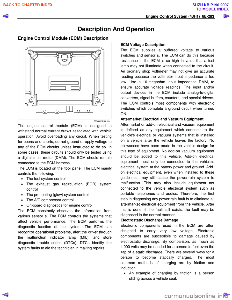
RTW 66ESH001201
The engine control module (ECM) is designed to
withstand normal current draws associated with vehicle
operation. Avoid overloading any circuit. W hen testing
for opens and shorts, do not ground or apply voltage to
any of the ECM circuits unless instructed to do so. In
some cases, these circuits should only be tested using
a digital multi meter (DMM). The ECM should remain
connected to the ECM harness.
The ECM is located on the floor panel. The ECM mainl
y
controls the following.
• The fuel system control
• The exhaust gas recirculation (EGR) system
control
• The preheating (glow) system control
• The A/C compressor control
• On-board diagnostics for engine control
The ECM constantly observes the information from
various sensor s. The ECM controls the systems that
affect vehicle performance. The ECM performs the
diagnostic function of the system. The ECM can
recognize operational problems, alert the driver through
the malfunction indicator lamp (MIL), and store
diagnostic trouble codes (DTCs). DTCs identify the
system faults to aid the technician in making repairs.
ECM Voltage Description
The ECM supplies a buffered voltage to various
switches and sensor s. The ECM can do this because
resistance in the ECM is so high in value that a test
lamp may not illuminate when connected to the circuit.
An ordinary shop voltmeter may not give an accurate
reading because the voltmeter input impedance is too
low. Use a 10-megaohm input impedance DMM, to
ensure accurate voltage readings. The input and/o
r
output devices in the ECM include analog-to-digital
converters, signal buffers, counters, and special drivers.
The ECM controls most components with electronic
switches which complete a ground circuit when turned
ON.
Aftermarket Electrical and Vacuum Equipment
Aftermarket or add-on electrical and vacuum equipment
is defined as any equipment which connects to the
vehicle's electrical or vacuum systems that is installed
on a vehicle after the vehicle leaves the factory. No
allowances have been made in the vehicle design fo
r
this type of equipment. No add-on vacuum equipment
should be added to this vehicle. Add-on electrical
equipment must only be connected to the vehicle's
electrical system at the battery power and ground. Add-
on electrical equipment, even when installed to these
guidelines, may still cause the powertrain system to
malfunction. This may also include equipment not
connected to the vehicle electrical system such as
portable telephones and audios. Therefore, the first
step in diagnosing any powertrain fault is to eliminate all
aftermarket electrical equipment from the vehicle. Afte
r
this is done, if the fault still exists, the fault may be
diagnosed in the normal manner.
Electrostatic Discharge Damage
Electronic components used in the ECM are often
designed to carry very low voltage. Electronic
components are susceptible to damage caused b
y
electrostatic discharge. By comparison, as much as
4,000 volts may be needed for a person to feel even the
zap of a static discharge. There are several ways for a
person to become statically charged. The most
common methods of charging are by friction and
induction. •
An example of charging by friction is a person
sliding across a vehicle seat.
BACK TO CHAPTER INDEX
TO MODEL INDEX
ISUZU KB P190 2007
Page 1363 of 6020
ENGINE MECHANICAL (4JK1/4JJ1) 6A-3
ISUZU DIESEL ENGINE (4JK1/4JJ1)
Service Precautions
Matters that require attention in terms of
maintenance
To prevent damage to the engine and ensure reliabilit
y
of its performance, pay attention to the following in
maintaining the engine:
• W hen lifting up or supporting the engine, do not
apply a jack on the oil pan.
W hen taking down the engine on the ground, do not make the bearing surface of the oil pan touch
the ground directly. Use a wooden frame, fo
r
example, to support the engine with the engine
foot and the flywheel housing.
Because there is only a small clearance between the oil pan and the oil pump strainer, it can
damage the oil pan and the oil strainer.
• W hen the air duct or air cleaner is removed, cove
r
the air intake opening to prevent foreign matter
from getting into the cylinder. If it gets
contaminated, it can considerably damage the
cylinder and others while the engine is operating.
• W hen maintaining the engine, never fail to remove
the battery earth cable. If not, it may damage the
wire harness or electrical parts. If you need
electricity on for the purpose of inspection, fo
r
instance, watch out for short circuits and others.
•
Apply engine oil to the sliding contact surfaces of
the engine before reassembling it. This ensures
adequate lubrication when the engine is first
started.
• W hen valve train parts, pistons, piston rings,
connecting rods, connecting rod bearings o
r
crankshaft journal bearings are removed, put them
in order and keep them.
• W hen installing them, put them back in the same
location they were removed from.
• Gaskets, oil seals, O-rings, etc. must be replaced
with new ones when the engine is reassembled.
•
As for parts where a liquid gasket is used, remove
an old liquid gasket completely and clean it up
thoroughly so that no oil, water or dust is clinging
to them. Then, apply the designated liquid gasket
to each place anew before assembly.
• Surfaces covered with liquid gasket must be
assembled within 5 minutes of gasket application.
If more than 5 minutes has elapsed, remove the
existing liquid gasket and apply a new liquid
gasket.
• W hen assembling or installing parts, fasten them
with the prescribed tightening torque so that the
y
are installed properly.
Matters that require attention in specifically dealing
with this engine.
Holes or clearances in the fuel system, which serve as
a passage of fuel, including the inside of the injector,
are made with extreme precision. For this reason, the
y
are highly sensitive to foreign matter and, if it gets in, it
can lead to an accident on the road, for instance; thus,
make sure that foreign matter is prevented from getting
in.
W hen servicing the fuel system, every precaution must
be taken to prevent the entry of foreign material into the
system.
• Before beginning the service procedure, wash the
fuel line and the surrounding area.
• Perform the service procedures with clean hands.
Do not wear work gloves.
• Immediately after removing the fuel hose and/o
r
fuel pipe, carefully tape vinyl bags over the
exposed ends of the hose or pipe.
• If parts are to be replaced (fuel hose, fuel pipe,
etc.) do not open the new part packaging until
installation.
Work procedure
• The fuel opening must be quickly sealed when
removing the fuel pipe, injection pipe, fuel injector,
fuel supply pump, and fuel rail.
• The eyebolts and gasket must be stored in a clean
parts box with a lid to prevent adhesion of foreign
matter.
• Fuel leakage could cause fires. Therefore, afte
r
finishing the work, wipe off the fuel that has leaked
out and make sure there is no fuel leakage afte
r
starting the engine.
BACK TO CHAPTER INDEX
TO MODEL INDEX
ISUZU KB P190 2007
Page 1366 of 6020
6A-6 ENGINE MECHANICAL (4JK1/4JJ1)
• Insert a 0.15 mm (0.006 in) thickness gauge
between the roller of the rocker arm and the
camshaft to tighten up the adjusting screw o
f
the rocker arm. W hen the movement of the
thickness gauge becomes tight, fasten the
adjusting screw nut of the rocker arm.
Valve clearance mm (in)
Intake valve 0.15 (0.006)
Exhaust valve 0.15 (0.006)
Note:
Adjust while cold.
2. Adjustment of valve clearance • Loosen each adjusting screw of the rocker arm
completely.
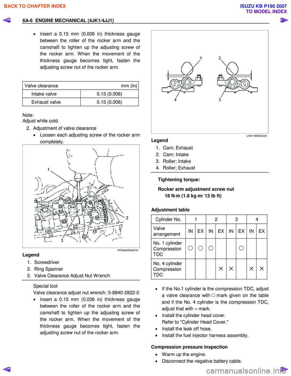
RTW 56ASH003701
Legend
1. Screwdriver
2. Ring Spanner
3. Valve Clearance Adjust Nut W rench
Special tool
Valve clearance adjust nut wrench: 5-8840-2822-0
• Insert a 0.15 mm (0.006 in) thickness gauge
between the roller of the rocker arm and the
camshaft to tighten up the adjusting screw o
f
the rocker arm. W hen the movement of the
thickness gauge becomes tight, fasten the
adjusting screw nut of the rocker arm.
LHW 71BSH001201
Legend
1. Cam; Exhaust
2. Cam; Intake
3. Roller; Intake
4. Roller; Exhaust
Tightening torque:
Rocker arm adjustment screw nut 18 N ⋅
⋅⋅
⋅
m (1.8 kg ⋅
⋅⋅
⋅
m/ 13 lb ft)
Adjustment table
Cylinder No. 1 2 3 4
Valve
arrangement IN EX IN EX IN EX IN EX
No. 1 cylinder
Compression
TDC
No. 4 cylinder
Compression
TDC
× × × ×
• If the No.1 cylinder is the compression TDC, adjust
a valve clearance with
mark given on the table
and if the No. 4 cylinder is the compression TDC,
adjust that with × mark.
• Install the cylinder head cover.
Refer to "Cylinder Head Cover."
• Install the leak off hose.
• Install the fuel injector harness assembly.
Compression pressure inspection
• W arm up the engine.
• Disconnect the negative battery cable.
BACK TO CHAPTER INDEX
TO MODEL INDEX
ISUZU KB P190 2007
Page 1367 of 6020
ENGINE MECHANICAL (4JK1/4JJ1) 6A-7
• Remove the all glow plugs.
Note:
W hen the harness connector is removed, ECM judges
that it broke down and DTC is recorded. Upon
completion of measurement, never fail to clear the
memory of the ECM.
(For how to clear the memory of the ECM, refer to
“ENGINE CONTROL SYSTEM” Section)
• Connect the negative battery cable.
• Turn on the starter to emit foreign matter within the
cylinders.
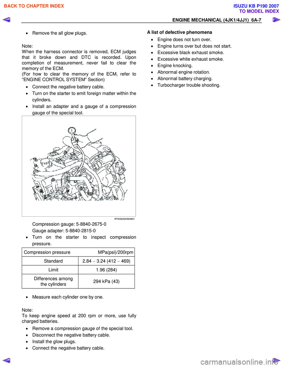
• Install an adapter and a gauge of a compression
gauge of the special tool.
RTW 56ASH003801
Compression gauge: 5-8840-2675-0
Gauge adapter: 5-8840-2815-0
• Turn on the starter to inspect compression
pressure.
Compression pressure MPa(psi)/200rpm
Standard 2.84 − 3.24 (412 − 469)
Limit 1.96 (284)
Differences among
the cylinders 294 kPa (43)
•
Measure each cylinder one by one.
Note:
To keep engine speed at 200 rpm or more, use full
y
charged batteries.
• Remove a compression gauge of the special tool.
• Disconnect the negative battery cable.
• Install the glow plugs.
• Connect the negative battery cable.
A list of defective phenomena
• Engine does not turn over.
• Engine turns over but does not start.
• Excessive black exhaust smoke.
• Excessive white exhaust smoke.
• Engine knocking.
• Abnormal engine rotation.
• Abnormal battery charging.
• Turbocharger trouble shooting.
BACK TO CHAPTER INDEX
TO MODEL INDEX
ISUZU KB P190 2007
Page 1368 of 6020
6A-8 ENGINE MECHANICAL (4JK1/4JJ1)
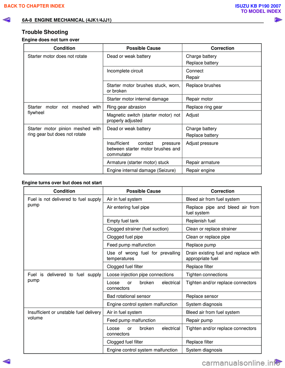
Trouble Shooting
Engine does not turn over
Condition Possible Cause Correction
Dead or weak battery Charge battery
Replace battery
Incomplete circuit Connect
Repair
Starter motor brushes stuck, worn,
or broken Replace brushes
Starter motor does not rotate
Starter motor internal damage Repair motor
Ring gear abrasion Replace ring gear Starter motor not meshed with
flywheel Magnetic switch (starter motor) not
properly adjusted Adjust
Dead or weak battery
Charge battery
Replace battery
Insufficient contact pressure
between starter motor brushes and
commutator Adjust pressure
Armature (starter motor) stuck Repair armature
Starter motor pinion meshed with
ring gear but does not rotate
Engine internal damage (Seizure) Repair engine
Engine turns over but does not start
Condition Possible Cause Correction
Air in fuel system Bleed air from fuel system
Air entering fuel pipe Replace pipe and bleed air from
fuel system
Empty fuel tank Replenish fuel
Clogged strainer (fuel suction) Clean or replace strainer
Clogged fuel pipe Clean or replace pipe
Feed pump malfunction Replace pump
Use of wrong fuel for prevailing
temperatures Drain existing fuel and replace with
appropriate fuel
Fuel is not delivered to fuel supply
pump
Clogged fuel filter Replace filter
Loose injection pipe connections Tighten connections
Loose or broken electrical
connectors Tighten and/or replace connectors
Bad rotational sensor
Replace sensor
Fuel is delivered to fuel supply
pump
Engine control system malfunction System diagnosis
Air in fuel system Bleed air from fuel system
Feed pump malfunction Repair pump
Loose or broken electrical
connectors Tighten and/or replace connectors
Clogged fuel filter
Replace filter
Insufficient or unstable fuel delivery
volume
Engine control system malfunction System diagnosis
BACK TO CHAPTER INDEX
TO MODEL INDEX
ISUZU KB P190 2007
Page 1371 of 6020
ENGINE MECHANICAL (4JK1/4JJ1) 6A-11
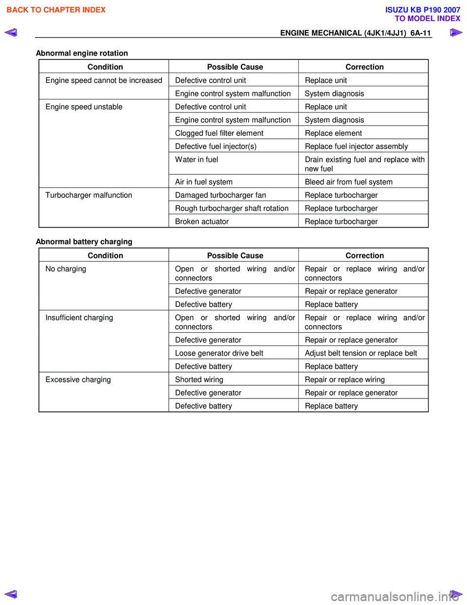
Abnormal engine rotation
Condition Possible Cause Correction
Defective control unit Replace unit Engine speed cannot be increased
Engine control system malfunction System diagnosis
Defective control unit Replace unit
Engine control system malfunction System diagnosis
Clogged fuel filter element Replace element
Defective fuel injector(s) Replace fuel injector assembly
W ater in fuel Drain existing fuel and replace with
new fuel
Engine speed unstable
Air in fuel system Bleed air from fuel system
Damaged turbocharger fan Replace turbocharger
Rough turbocharger shaft rotation Replace turbocharger
Turbocharger malfunction
Broken actuator Replace turbocharger
Abnormal battery charging
Condition Possible Cause Correction
Open or shorted wiring and/or
connectors Repair or replace wiring and/or
connectors
Defective generator Repair or replace generator
No charging
Defective battery Replace battery
Open or shorted wiring and/or
connectors Repair or replace wiring and/or
connectors
Defective generator Repair or replace generator
Loose generator drive belt Adjust belt tension or replace belt
Insufficient charging
Defective battery Replace battery
Shorted wiring Repair or replace wiring
Defective generator Repair or replace generator
Excessive charging
Defective battery Replace battery
BACK TO CHAPTER INDEX
TO MODEL INDEX
ISUZU KB P190 2007