Page 1596 of 6020
6D-8 ENGINE ELECTRICAL (4JK1/4JJ1)
Specifications
Battery power Volts 12
Generator output Amperes 90
Rotational direction (Viewed from pulley) Clockwise
Rated speed 5,000
Maximum speed rpm
18,000
BACK TO CHAPTER INDEX
TO MODEL INDEX
ISUZU KB P190 2007
Page 1601 of 6020
ENGINE ELECTRICAL (4JK1/4JJ1) 6D-13
Rectifier
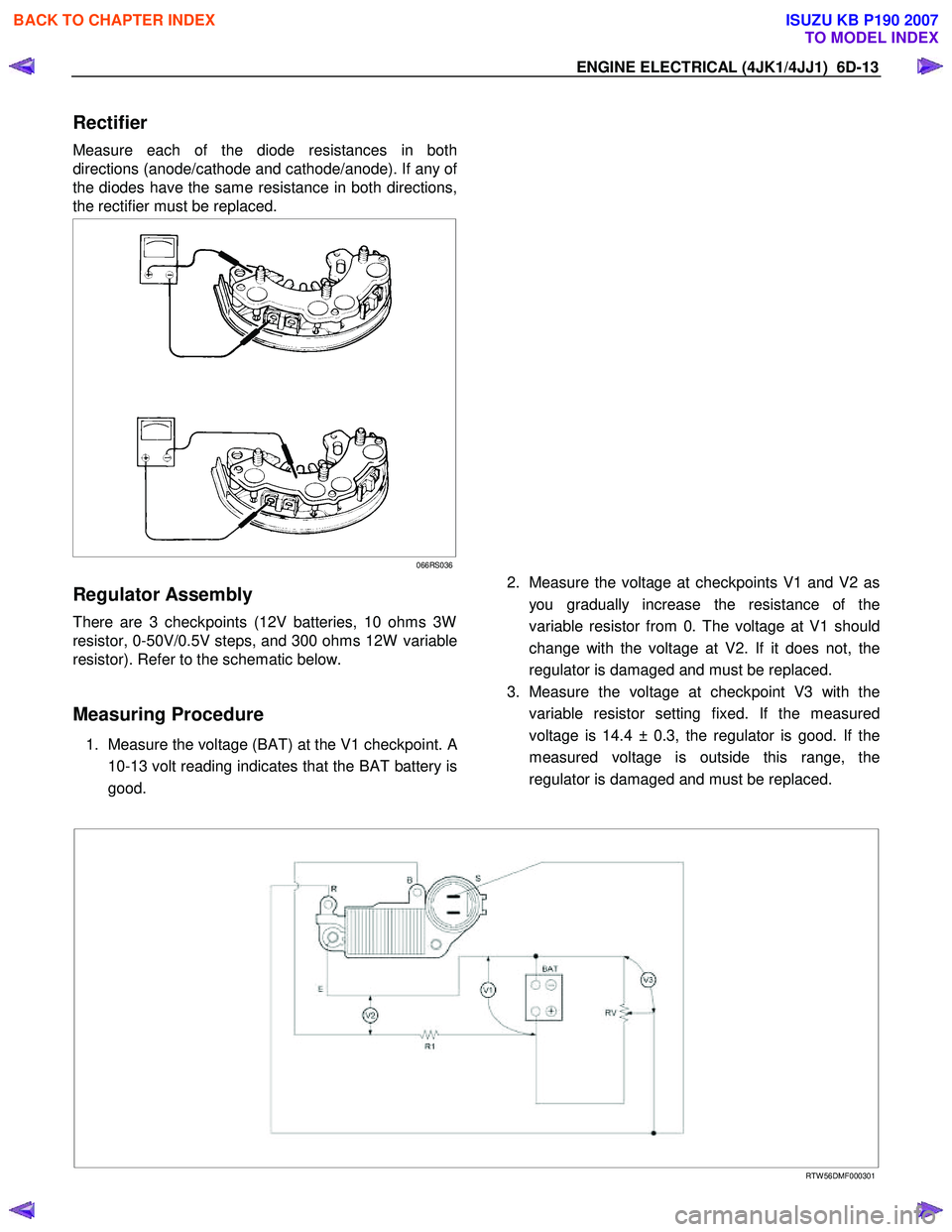
Measure each of the diode resistances in both
directions (anode/cathode and cathode/anode). If any o
f
the diodes have the same resistance in both directions,
the rectifier must be replaced.
066RS036
Regulator Assembly
There are 3 checkpoints (12V batteries, 10 ohms 3W
resistor, 0-50V/0.5V steps, and 300 ohms 12W variable
resistor). Refer to the schematic below.
Measuring Procedure
1. Measure the voltage (BAT) at the V1 checkpoint. A
10-13 volt reading indicates that the BAT battery is
good.
2. Measure the voltage at checkpoints V1 and V2 as
you gradually increase the resistance of the
variable resistor from 0. The voltage at V1 should
change with the voltage at V2. If it does not, the
regulator is damaged and must be replaced.
3. Measure the voltage at checkpoint V3 with the variable resistor setting fixed. If the measured
voltage is 14.4 ± 0.3, the regulator is good. If the
measured voltage is outside this range, the
regulator is damaged and must be replaced.
RTW 56DMF000301
BACK TO CHAPTER INDEX
TO MODEL INDEX
ISUZU KB P190 2007
Page 1602 of 6020
6D-14 ENGINE ELECTRICAL (4JK1/4JJ1)
Reassembly
Follow the disassembly steps in reverse order to
reassemble the generator. Pay close attention to the
items below.
• Be very careful not to reverse battery polarity.
Reversed battery polarity will destroy the rectifie
r
diodes.
• Do not ground the generator B-terminal. Heat and
fire damage to the harness will result.
• If using a fast charge procedure, be sure to
disconnect the battery positive cable. If you do not,
the rectifier diodes will be exposed to high positive
voltage that will destroy them.
• Be very careful to reassemble the parts to thei
r
original positions. Particular care must be taken
with insulated parts.
• Carefully clean all insulated parts so that they are
completely free of oil and/or grease.
• Be sure that B-terminal twist-type stoppers (round
terminal) are securely inserted before tightening
the nuts.
Final Assembly
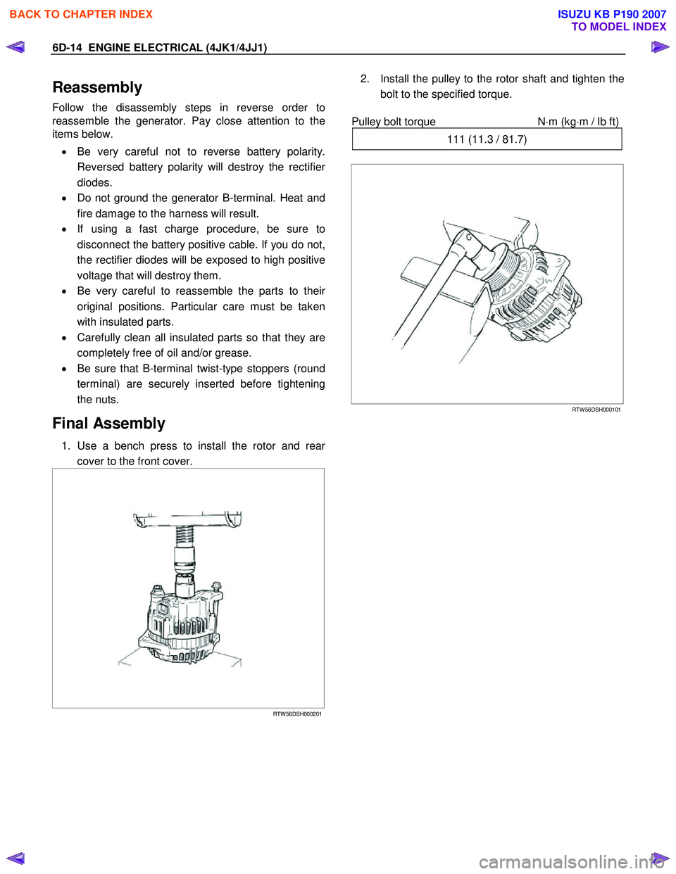
1. Use a bench press to install the rotor and rear
cover to the front cover.
RTW 56DSH000201
2. Install the pulley to the rotor shaft and tighten the
bolt to the specified torque.
Pulley bolt torque N
⋅m (kg⋅m / lb ft)
111 (11.3 / 81.7)
RTW 56DSH000101
BACK TO CHAPTER INDEX
TO MODEL INDEX
ISUZU KB P190 2007
Page 1603 of 6020
ENGINE ELECTRICAL (4JK1/4JJ1) 6D-15
Starter Motor
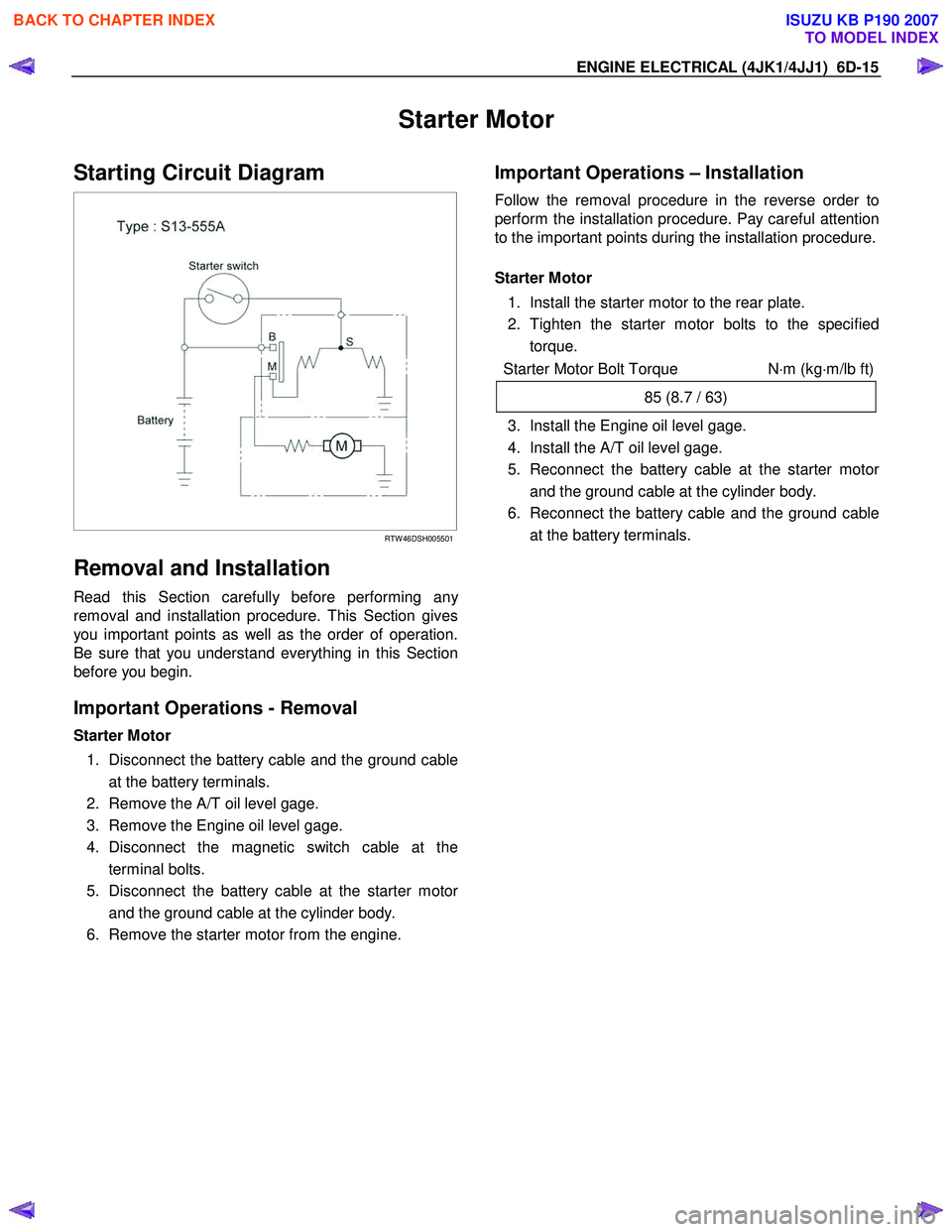
Starting Circuit Diagram
RTW 46DSH005501
Removal and Installation
Read this Section carefully before performing any
removal and installation procedure. This Section gives
you important points as well as the order of operation.
Be sure that you understand everything in this Section
before you begin.
Important Operations - Removal
Starter Motor
1. Disconnect the battery cable and the ground cable at the battery terminals.
2. Remove the A/T oil level gage.
3. Remove the Engine oil level gage.
4. Disconnect the magnetic switch cable at the terminal bolts.
5. Disconnect the battery cable at the starter moto
r
and the ground cable at the cylinder body.
6. Remove the starter motor from the engine.
Important Operations – Installation
Follow the removal procedure in the reverse order to
perform the installation procedure. Pay careful attention
to the important points during the installation procedure.
Starter Motor
1. Install the starter motor to the rear plate.
2. Tighten the starter motor bolts to the specified torque.
Starter Motor Bolt Torque N⋅m (kg ⋅m/lb ft)
85 (8.7 / 63)
3. Install the Engine oil level gage.
4. Install the A/T oil level gage.
5. Reconnect the battery cable at the starter moto
r
and the ground cable at the cylinder body.
6. Reconnect the battery cable and the ground cable at the battery terminals.
BACK TO CHAPTER INDEX
TO MODEL INDEX
ISUZU KB P190 2007
Page 1615 of 6020
ENGINE ELECTRICAL (4JK1/4JJ1) 6D-27
Magnetic Switch
The following tests must be performed with the starter
motor fully assembled.
The yoke lead wire must be disconnected from the “M”
terminal.
To prevent coil burning, complete each test as quickl
y
as possible (within three to five seconds).
Temporarily connect the solenoid switch between the
clutch and the housing and run the following test.
Complete each test within three to five seconds.
1. Pull-in Test
Connect the battery negative terminal with the solenoid switch body and the M terminal. W hen
current is applied to the S terminal from the batter
y
positive terminal, the pinion should flutter.
RTW 46DSH004601
2. Hold-in Maintenance Test
Disconnect the lead at the M terminal. The pinion should continue to flutter.
RTW 46DSH005901
3. Return Test
Disconnect the battery positive lead at the S terminal.
The pinion should return to its home position.
RTW 46DSH004701
BACK TO CHAPTER INDEX
TO MODEL INDEX
ISUZU KB P190 2007
Page 1624 of 6020
ENGINE CONTROL SYSTEM (4JK1/4JJ1) 6E-7
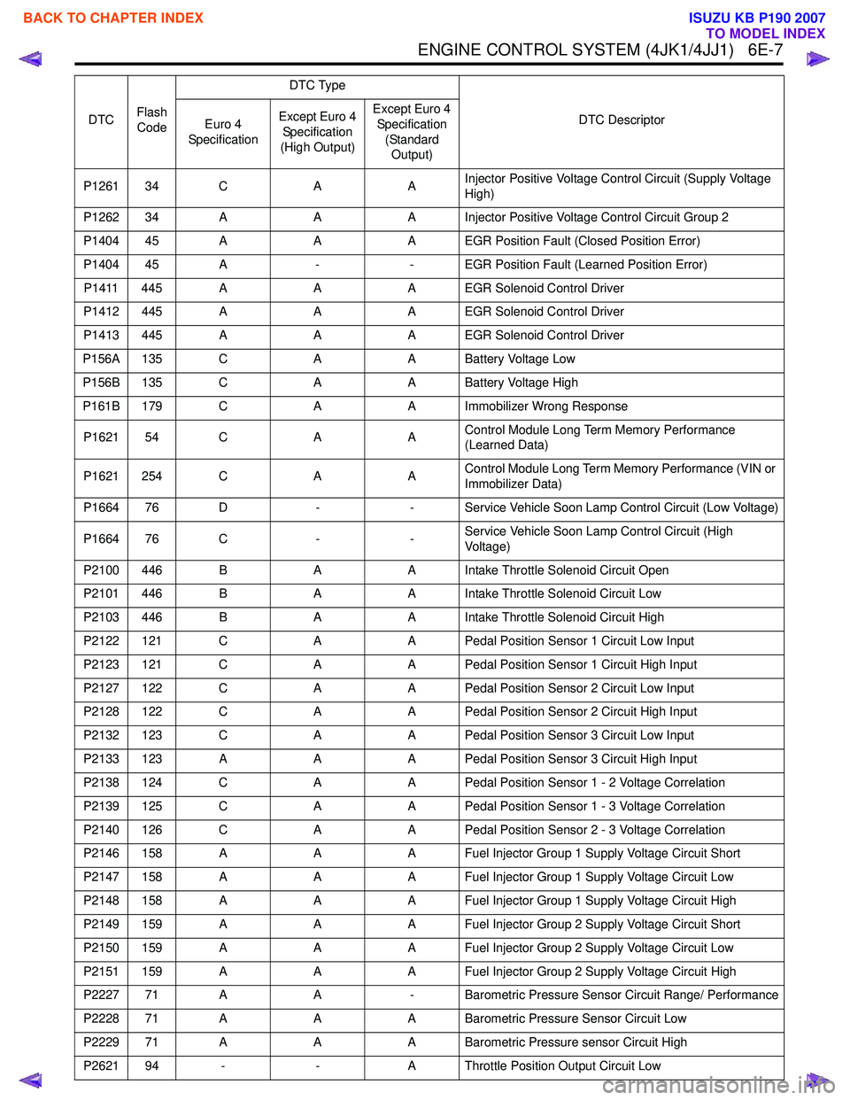
P1261 34 CAAInjector Positive Voltage Control Circuit (Supply Voltage
High)
P1262 34 A AA Injector Positive Voltage Control Circuit Group 2
P1404 45 A AA EGR Position Fault (Closed Position Error)
P1404 45 A -- EGR Position Fault (Learned Position Error)
P1411 445 A AA EGR Solenoid Control Driver
P1412 445 A AA EGR Solenoid Control Driver
P1413 445 A AA EGR Solenoid Control Driver
P156A 135 C AA Battery Voltage Low
P156B 135 C AA Battery Voltage High
P161B 179 C AA Immobilizer Wrong Response
P1621 54 C AAControl Module Long Term Memory Performance
(Learned Data)
P1621 254 C AAControl Module Long Term Memory Performance (VIN or
Immobilizer Data)
P1664 76 D -- Service Vehicle Soon Lamp Control Circuit (Low Voltage)
P1664 76 C --Service Vehicle Soon Lamp Control Circuit (High
Voltage)
P2100 446 B AA Intake Throttle Solenoid Circuit Open
P2101 446 B AA Intake Throttle Solenoid Circuit Low
P2103 446 B AA Intake Throttle Solenoid Circuit High
P2122 121 C AA Pedal Position Sensor 1 Circuit Low Input
P2123 121 C AA Pedal Position Sensor 1 Circuit High Input
P2127 122 C AA Pedal Position Sensor 2 Circuit Low Input
P2128 122 C AA Pedal Position Sensor 2 Circuit High Input
P2132 123 C AA Pedal Position Sensor 3 Circuit Low Input
P2133 123 A AA Pedal Position Sensor 3 Circuit High Input
P2138 124 C AA Pedal Position Sensor 1 - 2 Voltage Correlation
P2139 125 C AA Pedal Position Sensor 1 - 3 Voltage Correlation
P2140 126 C AA Pedal Position Sensor 2 - 3 Voltage Correlation
P2146 158 A AA Fuel Injector Group 1 Supply Voltage Circuit Short
P2147 158 A AA Fuel Injector Group 1 Supply Voltage Circuit Low
P2148 158 A AA Fuel Injector Group 1 Supply Voltage Circuit High
P2149 159 A AA Fuel Injector Group 2 Supply Voltage Circuit Short
P2150 159 A AA Fuel Injector Group 2 Supply Voltage Circuit Low
P2151 159 A AA Fuel Injector Group 2 Supply Voltage Circuit High
P2227 71 A A- Barometric Pressure Sensor Circuit Range/ Performance
P2228 71 A AA Barometric Pressure Sensor Circuit Low
P2229 71 A AA Barometric Pressure sensor Circuit High
P2621 94 - -A Throttle Position Output Circuit Low
DTC
Flash
Code DTC Type
DTC Descriptor
Euro 4
Specification Except Euro 4
Specification
(High Output) Except Euro 4
Specification (Standard Output)
BACK TO CHAPTER INDEX
TO MODEL INDEX
ISUZU KB P190 2007
Page 1627 of 6020
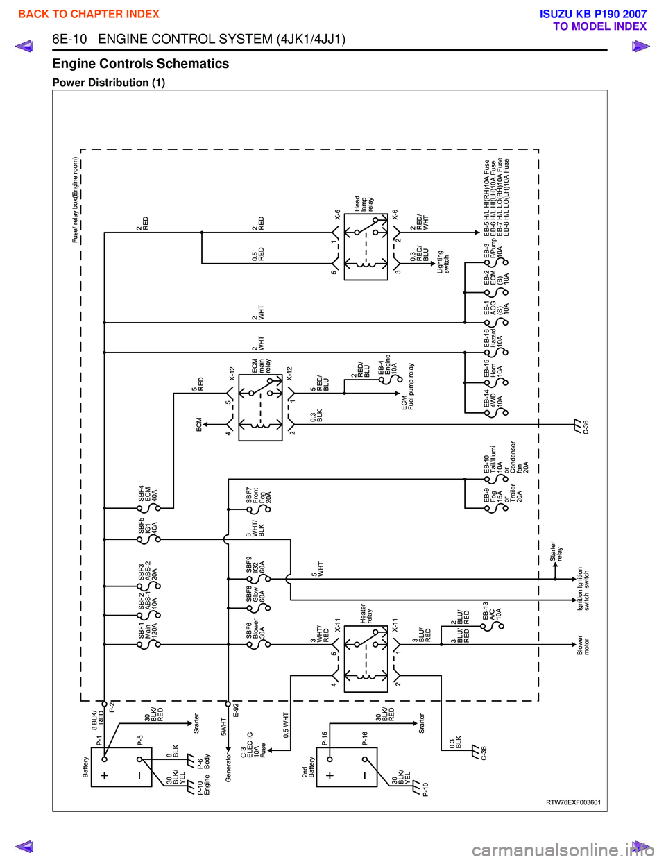
6E-10 ENGINE CONTROL SYSTEM (4JK1/4JJ1)
Engine Controls Schematics
Power Distribution (1)
RTW76EXF003601
X-11
X-11 Heater
relay
1
2
Blower
motor Ignition
switchIgnition
switch Starter
relay
SBF1
Main
120A SBF2
ABS-1
40A SBF3
ABS-2
20A SBF5
IG1
40A SBF4
ECM
40A
SBF6
Blower
30A
EB-13�
A/C
10A
2�
BLU/
RED
3�
BLU/
RED 3�
BLU/
RED SBF8
Glow
60A
SBF7
Front
Fog
20A
SBF9
IG2
60A
EB-9�
Fog
15A
or
Trailer
20AEB-10�
Tail/Illumi
10A
or
Condenser
fan
20A EB-4
Engine
10A
EB-14�
4WD
10A EB-15�
Horn
10A EB-16�
Hazard10A EB-1�
ACG
(S)
10AEB-2�
ECM
(B)
10AEB-3�
F/Pump10A
EB-5 H/L HI(RH)10A Fuse
EB-6 H/L HI(LH)10A Fuse
EB-7 H/L LO(RH)10A Fuse
EB-8 H/L LO(LH)10A Fuse
P-6
Body
Generator P-5
8 BLK/
P-1
P-2
Battery
8�
BLK 5WHTSrarter
Srarter
C-3
ELEC IG
10A
Fuse
E-92
0.5 WHT
0.3�
BLK 3�
WHT/
RED 5�
WHT
0.3�
BLK 5�
RED/
BLU
5�
RED
3�
WHT/
BLK
30�
BLK/
RED
30�
BLK/
YEL
P-10�
Engine
5
4 X-12
X-12
ECM
Fuel pump relay
ECM
ECM
main
relay
1
2 5
4
X-6
X-6
2�
RED/
WHT
0.3
RED/
BLU Fuse/ relay box(Engine room)
2�
RED
2�
RED
0.5�
RED
2�
WHT
2�
RED/
BLU 2�
WHT
2
3 1
5
Lighting
switch Head
lamp
relay
C-36 C-36
RED
P-16
P-15
2nd
Battery
30�
BLK/
YEL 30�
BLK/
RED
P-10�
BACK TO CHAPTER INDEX
TO MODEL INDEX
ISUZU KB P190 2007
Page 1629 of 6020
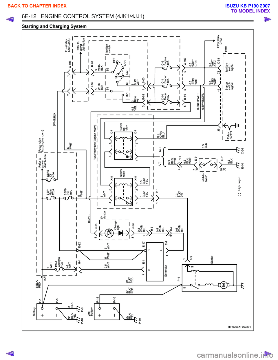
6E-12 ENGINE CONTROL SYSTEM (4JK1/4JJ1)
Starting and Charging System
RTW76EXF003801
EB-1
ACG(S)
10A
0.5�
WHT
2�
WHT
SBF1
Main
120A SBF5
IG1
40A Refer to
power
distribution Fuse/ relay
box(Engine room)
SBF9
IG2
60A
5
WHT 5�
WHT
P-8 P-5
8 BLK/
RED
P-1
P-2
Battery
8�
BLK
30�
BLK/
YEL
P-10�
P-16
P-15
2nd
Battery
30
BLK/
RED
30
BLK/
RED
30�
BLK/
YEL
P-10� X-8
X-8
E-4
Generator H-1Starter
relay
1
1
H-4 E-92
8
2
4
E-4 E-17
2 B-23
3 B-24
8
3 X-7
X-7 Starter
cut
relay
1 3
45
Starter
P-4
1
B
S
SB
L
P-3 0.3�
WHT/
BLU
5�
WHT
5�
WHT
0.5�
WHT
Charge
lightIP
cluster
H-6
1
0.5�
WHT/
BLU
0.5�
WHT/
BLU H-49
1 C-108
3�
WHT/
BLK
3�
WHT/
BLK
3�
BLK/
YEL
0.5�
YEL 3�
BLK/
WHT B-62
B-63
2
3
C-14�
Meter
10A C-1�
Starter
10A C-6�
Engine
10A
0.5
WHT/
GRN
0.5�
WHT/
GRN
0.5
RED/
WHT
0.5RED/WHT
0.5WHT/GRN
0.5�
RED/
WHT
Starter switchsignal Ignition
switchsignal Glow relay
DRM
ECM Refer to
power
distribution
Fuse/relay
box(Cabin)
1
2
3 B-62 1 B-63
5 5 9 C-107
B-56
44
35 72
B1
B2
OFF
ACC
IG2
ST
IG1 Ignition
switch
Relay
control
4
0.3
BLK/
WHT
3
BLK/
YEL
0.3
BLK/
YEL
3�
WHT
0.5YEL
Fuse/relay box(Engine room)3WHT/BLK
0.5
BLU/
YEL
H-4
A/T
M/T
C-36
E-10 0.5�
BLK/
WHT
Inhibitor
switch 0.3�
BLK 0.5�
ORN/
BLU
0.5�
BLK E-51
7
(4)
E-51
10
(1) C-58
( )...High output
BACK TO CHAPTER INDEX
TO MODEL INDEX
ISUZU KB P190 2007