2007 ISUZU KB P190 oil
[x] Cancel search: oilPage 3520 of 6020
Engine Management – V6 – Diagnostics Page 6C1-2–242
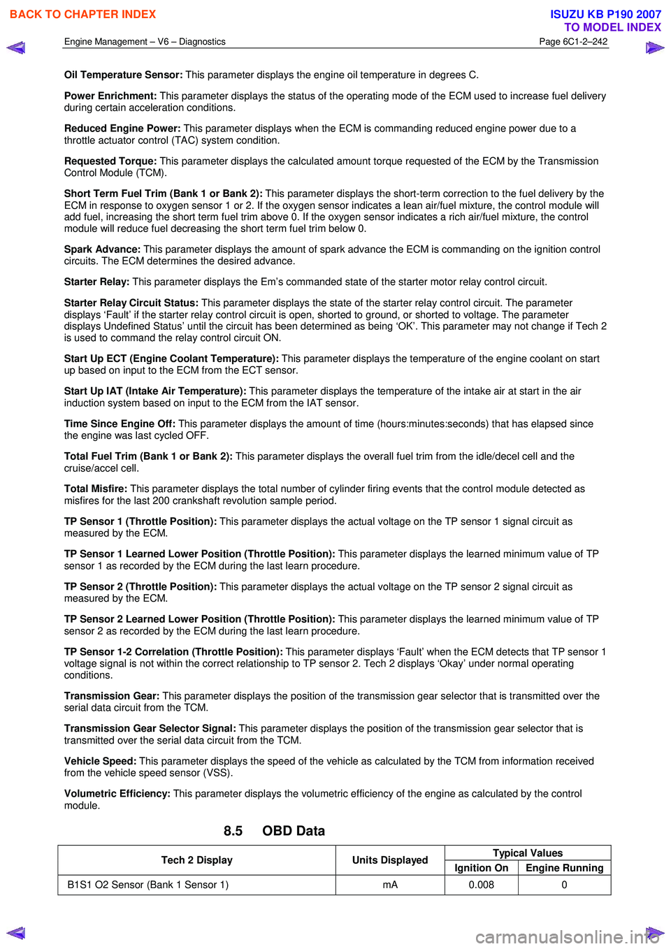
Oil Temperature Sensor: This parameter displays the engine oil temperature in degrees C.
Power Enrichment: This parameter displays the status of the operating mode of the ECM used to increase fuel delivery
during certain acceleration conditions.
Reduced Engine Power: This parameter displays when the ECM is commanding reduced engine power due to a
throttle actuator control (TAC) system condition.
Requested Torque: This parameter displays the calculated amount torque requested of the ECM by the Transmission
Control Module (TCM).
Short Term Fuel Trim (Bank 1 or Bank 2): This parameter displays the short-term correction to the fuel delivery by the
ECM in response to oxygen sensor 1 or 2. If the oxygen sensor indicates a lean air/fuel mixture, the control module will
add fuel, increasing the short term fuel trim above 0. If the oxygen sensor indicates a rich air/fuel mixture, the control
module will reduce fuel decreasing the short term fuel trim below 0.
Spark Advance: This parameter displays the amount of spark advance the ECM is commanding on the ignition control
circuits. The ECM determines the desired advance.
Starter Relay: This parameter displays the Em’s commanded state of the starter motor relay control circuit.
Starter Relay Circuit Status: This parameter displays the state of the starter relay control circuit. The parameter
displays ‘Fault’ if the starter relay control circuit is open, shorted to ground, or shorted to voltage. The parameter
displays Undefined Status’ until the circuit has been determined as being ‘OK’. This parameter may not change if Tech 2
is used to command the relay control circuit ON.
Start Up ECT (Engine Coolant Temperature): This parameter displays the temperature of the engine coolant on start
up based on input to the ECM from the ECT sensor.
Start Up IAT (Intake Air Temperature): This parameter displays the temperature of the intake air at start in the air
induction system based on input to the ECM from the IAT sensor.
Time Since Engine Off: This parameter displays the amount of time (hours:minutes:seconds) that has elapsed since
the engine was last cycled OFF.
Total Fuel Trim (Bank 1 or Bank 2): This parameter displays the overall fuel trim from the idle/decel cell and the
cruise/accel cell.
Total Misfire: This parameter displays the total number of cylinder firing events that the control module detected as
misfires for the last 200 crankshaft revolution sample period.
TP Sensor 1 (Throttle Position): This parameter displays the actual voltage on the TP sensor 1 signal circuit as
measured by the ECM.
TP Sensor 1 Learned Lower Position (Throttle Position): This parameter displays the learned minimum value of TP
sensor 1 as recorded by the ECM during the last learn procedure.
TP Sensor 2 (Throttle Position): This parameter displays the actual voltage on the TP sensor 2 signal circuit as
measured by the ECM.
TP Sensor 2 Learned Lower Position (Throttle Position): This parameter displays the learned minimum value of TP
sensor 2 as recorded by the ECM during the last learn procedure.
TP Sensor 1-2 Correlation (Throttle Position): This parameter displays ‘Fault’ when the ECM detects that TP sensor 1
voltage signal is not within the correct relationship to TP sensor 2. Tech 2 displays ‘Okay’ under normal operating
conditions.
Transmission Gear: This parameter displays the position of the transmission gear selector that is transmitted over the
serial data circuit from the TCM.
Transmission Gear Selector Signal: This parameter displays the position of the transmission gear selector that is
transmitted over the serial data circuit from the TCM.
Vehicle Speed: This parameter displays the speed of the vehicle as calculated by the TCM from information received
from the vehicle speed sensor (VSS).
Volumetric Efficiency: This parameter displays the volumetric efficiency of the engine as calculated by the control
module.
8.5 OBD Data
Typical Values Tech 2 Display Units Displayed
Ignition On Engine Running
B1S1 O2 Sensor (Bank 1 Sensor 1) mA 0.008 0
BACK TO CHAPTER INDEX
TO MODEL INDEX
ISUZU KB P190 2007
Page 3526 of 6020
Engine Management – V6 – Service Operations Page 6C1-3–2
Reinstall ................................................................................................................................................................ 20
ECM Reset ...................................................................................................................... ...................................... 20
2.8 Engine Control Module Bracket Assembly......................................................................................... ............... 21
Remove ................................................................................................................................................................. 21
Reinstall ................................................................................................................................................................ 21
2.9 Engine Oil Level and Temperature Sensor ........................................................................................ ................ 22
Remove ................................................................................................................................................................. 22
Test ....................................................................................................................................................................... 23
Engine Oil Level Sensor Check .................................................................................................. ...................... 23
Reinstall ................................................................................................................................................................ 23
2.10 Engine Oil Pressure Sensor..................................................................................................... ........................... 23
Remove ................................................................................................................................................................. 23
Reinstall ................................................................................................................................................................ 24
2.11 Evaporative Emission (EVAP) Canister Purge Valve Quick Connect Fittings ................................................ 24
Disconnect..................................................................................................................... ....................................... 24
Locking Lever Type ............................................................................................................. ............................. 25
Latch Type ....................................................................................................................................................... 25
Connect ............................................................................................................................................................ 25
2.12 Evaporative Emission Canister Purge Valve ...................................................................................... ............... 26
Remove ................................................................................................................................................................. 26
Test ....................................................................................................................................................................... 27
Resistance Check ............................................................................................................... ............................. 27
Functional Test................................................................................................................................................. 27
Reinstall ................................................................................................................................................................ 28
2.13 Fuel Rail Assembly ............................................................................................................. ................................. 28
Remove ................................................................................................................................................................. 28
Disassemble ......................................................................................................................................................... 30
Fuel Injector ..................................................................................................................................................... 30
Fuel Injector Wiring Harness Assembly.......................................................................................... .................. 32
Reinstall ................................................................................................................................................................ 33
2.14 Heated Oxygen Sensor........................................................................................................... ............................. 33
Service Precautions............................................................................................................................................. 33
Six Wire Sensor................................................................................................................................................ 34
Four Wire Sensor ............................................................................................................... .............................. 35
Test ....................................................................................................................................................................... 37
Heater Resistance Check – Six Wire HO2S........................................................................................ ............. 37
Heater Resistance Check – Four Wire HO2S ....................................................................................... ........... 37
2.15 Ignition Coil .......................................................................................................................................................... 38
Ignition Coils ................................................................................................................. ....................................... 38
Remove ............................................................................................................................................................ 38
Disassemble..................................................................................................................................................... 39
Reassemble ..................................................................................................................................................... 39
Test .................................................................................................................................................................. 39
Reinstall ........................................................................................................................................................... 40
2.16 Intake Air Duct Assembly....................................................................................................... ............................. 40
Remove ................................................................................................................................................................. 40
Reinstall ................................................................................................................................................................ 40
2.17 Intake Air Temperature Sensor .................................................................................................. ......................... 41
Test ....................................................................................................................................................................... 41
Resistance Check ............................................................................................................... ............................. 41
2.18 Knock Sensor, Bank 2 (LHS)..................................................................................................... .......................... 42
Remove ................................................................................................................................................................. 42
Reinstall ................................................................................................................................................................ 43
2.19 Knock Sensor, Bank 1 (RHS) ..................................................................................................... ......................... 43
Remove ................................................................................................................................................................. 43
Reinstall ................................................................................................................................................................ 44
2.20 Mass Air Flow Sensor........................................................................................................... ............................... 45
Handling Precautions .......................................................................................................................................... 45
Remove ................................................................................................................................................................. 45
Reinstall ................................................................................................................................................................ 46
BACK TO CHAPTER INDEX
TO MODEL INDEX
ISUZU KB P190 2007
Page 3537 of 6020
Engine Management – V6 – Service Operations Page 6C1-3–13
Clean the area around the CMP sensor before
removal to avoid debris from entering the
engine.
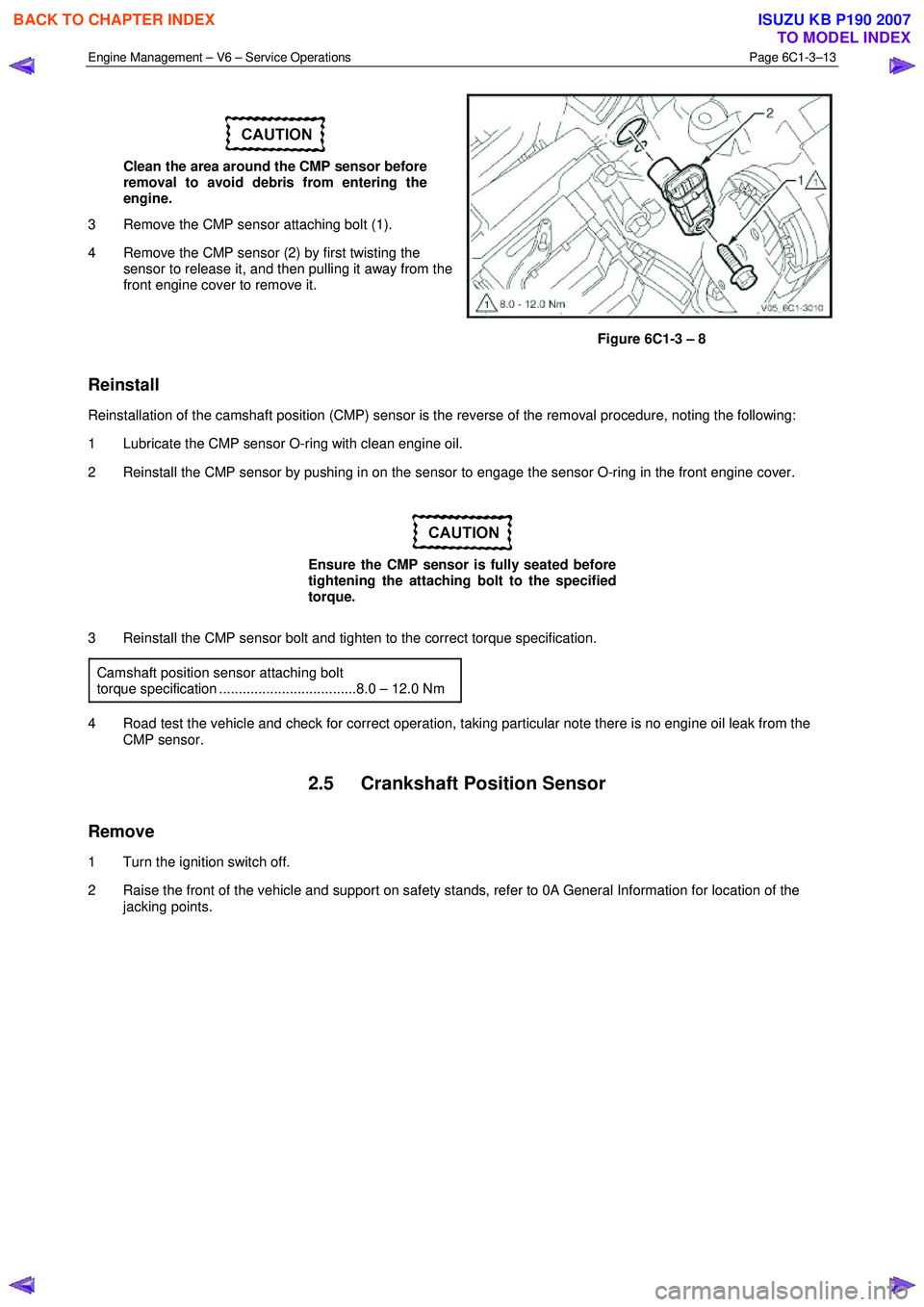
3 Remove the CMP sensor attaching bolt (1).
4 Remove the CMP sensor (2) by first twisting the sensor to release it, and then pulling it away from the
front engine cover to remove it.
Figure 6C1-3 – 8
Reinstall
Reinstallation of the camshaft position (CMP) sensor is the reverse of the removal procedure, noting the following:
1 Lubricate the CMP sensor O-ring with clean engine oil.
2 Reinstall the CMP sensor by pushing in on the sensor to engage the sensor O-ring in the front engine cover.
Ensure the CMP sensor is fully seated before
tightening the attaching bolt to the specified
torque.
3 Reinstall the CMP sensor bolt and tighten to the correct torque specification. Camshaft position sensor attaching bolt
torque specification ...................................8.0 – 12.0 Nm
4 Road test the vehicle and check for correct operation, taking particular note there is no engine oil leak from the CMP sensor.
2.5 Crankshaft Position Sensor
Remove
1 Turn the ignition switch off.
2 Raise the front of the vehicle and support on safety stands, refer to 0A General Information for location of the jacking points.
BACK TO CHAPTER INDEX
TO MODEL INDEX
ISUZU KB P190 2007
Page 3539 of 6020
Engine Management – V6 – Service Operations Page 6C1-3–15
Test
To prevent component and damage use
connector test adaptor kit J 35616-A.
Resistance Check
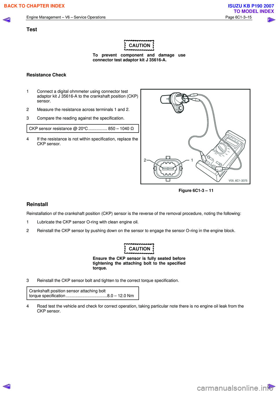
1 Connect a digital ohmmeter using connector test adaptor kit J 35616-A to the crankshaft position (CKP)
sensor.
2 Measure the resistance across terminals 1 and 2.
3 Compare the reading against the specification.
CKP sensor resistance @ 20°C ................ 850 – 1040 Ω
4 If the resistance is not within specification, replace the
CKP sensor.
Figure 6C1-3 – 11
Reinstall
Reinstallation of the crankshaft position (CKP) sensor is the reverse of the removal procedure, noting the following:
1 Lubricate the CKP sensor O-ring with clean engine oil.
2 Reinstall the CKP sensor by pushing down on the sensor to engage the sensor O-ring in the engine block.
Ensure the CKP sensor is fully seated before
tightening the attaching bolt to the specified
torque.
3 Reinstall the CKP sensor bolt and tighten to the correct torque specification. Crankshaft position sensor attaching bolt
torque specification ...................................8.0 – 12.0 Nm
4 Road test the vehicle and check for correct operation, taking particular note there is no engine oil leak from the CKP sensor.
BACK TO CHAPTER INDEX
TO MODEL INDEX
ISUZU KB P190 2007
Page 3546 of 6020
Engine Management – V6 – Service Operations Page 6C1-3–22
3 Road test the vehicle and check for correct operation.
2.9 Engine Oil Level and Temperature
Sensor
To avoid personal injury, take care when
draining the engine oil or removing the engine
oil level and temperature sensor whilst the
engine is hot. Allow the engine to cool before
performing this procedure.
Remove
1 Turn the ignition switch off.
2 Raise the front and rear of the vehicle and support on safety stands, refer to 0A General Information for location of the jacking points.
3 Drain the engine oil, refer to 6A1 Engine Mechanical – V6.
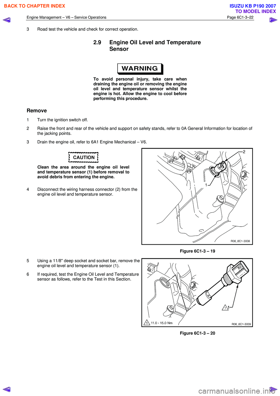
Clean the area around the engine oil level
and temperature sensor (1) before removal to
avoid debris from entering the engine.
4 Disconnect the wiring harness connector (2) from the engine oil level and temperature sensor.
Figure 6C1-3 – 19
5 Using a 11/8" deep socket and socket bar, remove the engine oil level and temperature sensor (1).
6 If required, test the Engine Oil Level and Temperature sensor as follows, refer to the Test in this Section.
Figure 6C1-3 – 20
BACK TO CHAPTER INDEX
TO MODEL INDEX
ISUZU KB P190 2007
Page 3547 of 6020
Engine Management – V6 – Service Operations Page 6C1-3–23
Test
Engine Oil Level Sensor Check
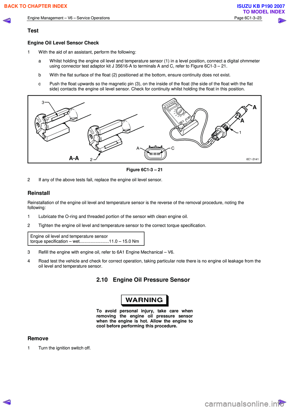
1 W ith the aid of an assistant, perform the following:
a W hilst holding the engine oil level and temperature sensor (1) in a level position, connect a digital ohmmeter using connector test adaptor kit J 35616-A to terminals A and C, refer to Figure 6C1-3 – 21.
b W ith the flat surface of the float (2) positioned at the bottom, ensure continuity does not exist.
c Push the float upwards so the magnetic pin (3), on the inside of the float (the side of the float with the flat side) contacts the engine oil level sensor. Check for continuity whilst holding the float in this position.
Figure 6C1-3 – 21
2 If any of the above tests fail, replace the engine oil level sensor.
Reinstall
Reinstallation of the engine oil level and temperature sensor is the reverse of the removal procedure, noting the
following:
1 Lubricate the O-ring and threaded portion of the sensor with clean engine oil.
2 Tighten the engine oil level and temperature sensor to the correct torque specification.
Engine oil level and temperature sensor
torque specification – wet........................11.0 – 15.0 Nm
3 Refill the engine with engine oil, refer to 6A1 Engine Mechanical – V6.
4 Road test the vehicle and check for correct operation, taking particular note there is no engine oil leakage from the oil level and temperature sensor.
2.10 Engine Oil Pressure Sensor
To avoid personal injury, take care when
removing the engine oil pressure sensor
when the engine is hot. Allow the engine to
cool before performing this procedure.
Remove
1 Turn the ignition switch off.
BACK TO CHAPTER INDEX
TO MODEL INDEX
ISUZU KB P190 2007
Page 3548 of 6020
Engine Management – V6 – Service Operations Page 6C1-3–24
Clean the area around the engine oil pressure
sensor before removal to avoid debris from
entering the engine.
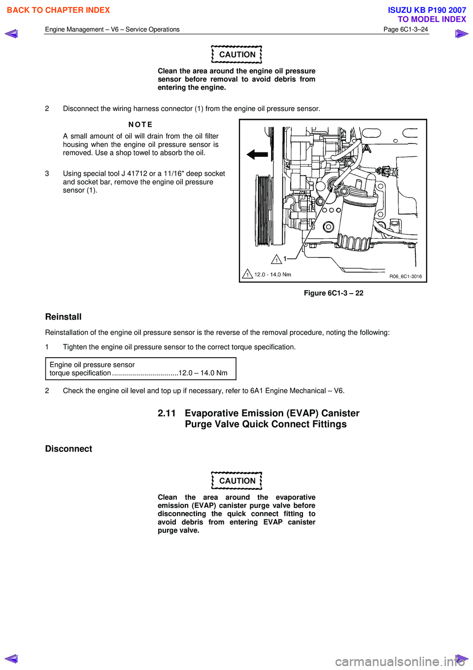
2 Disconnect the wiring harness connector (1) from the engine oil pressure sensor. NOTE
A small amount of oil will drain from the oil filter
housing when the engine oil pressure sensor is
removed. Use a shop towel to absorb the oil.
3 Using special tool J 41712 or a 11/16" deep socket and socket bar, remove the engine oil pressure
sensor (1).
Figure 6C1-3 – 22
Reinstall
Reinstallation of the engine oil pressure sensor is the reverse of the removal procedure, noting the following:
1 Tighten the engine oil pressure sensor to the correct torque specification.
Engine oil pressure sensor
torque specification .................................12.0 – 14.0 Nm
2 Check the engine oil level and top up if necessary, refer to 6A1 Engine Mechanical – V6.
2.11 Evaporative Emission (EVAP) Canister Purge Valve Quick Connect Fittings
Disconnect
Clean the area around the evaporative
emission (EVAP) canister purge valve before
disconnecting the quick connect fitting to
avoid debris from entering EVAP canister
purge valve.
BACK TO CHAPTER INDEX
TO MODEL INDEX
ISUZU KB P190 2007
Page 3549 of 6020
Engine Management – V6 – Service Operations Page 6C1-3–25
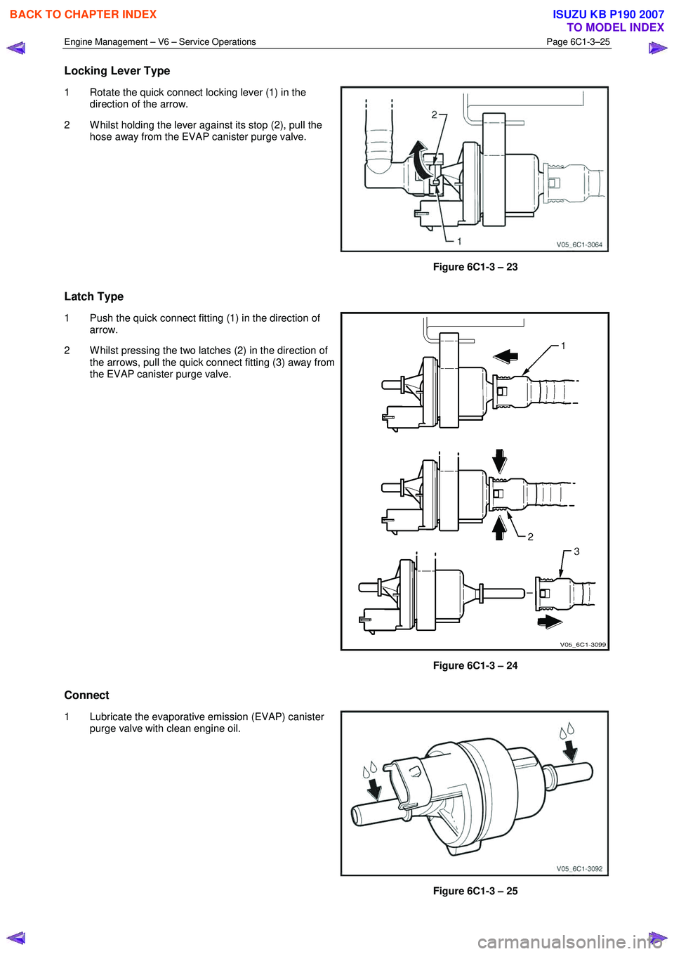
Locking Lever Type
1 Rotate the quick connect locking lever (1) in the
direction of the arrow.
2 W hilst holding the lever against its stop (2), pull the hose away from the EVAP canister purge valve.
Figure 6C1-3 – 23
Latch Type
1 Push the quick connect fitting (1) in the direction of
arrow.
2 W hilst pressing the two latches (2) in the direction of the arrows, pull the quick connect fitting (3) away from
the EVAP canister purge valve.
Figure 6C1-3 – 24
Connect
1 Lubricate the evaporative emission (EVAP) canister purge valve with clean engine oil.
Figure 6C1-3 – 25
BACK TO CHAPTER INDEX
TO MODEL INDEX
ISUZU KB P190 2007