2007 ISUZU KB P190 oil
[x] Cancel search: oilPage 3470 of 6020
Engine Management – V6 – Diagnostics Page 6C1-2–192
Additional Information
• A fuel delivery condition causes this DTC to set. Thoroughly inspect all items that could cause a rich condition.
• For an intermittent fault condition, refer to 5.2 Intermittent Fault Conditions in this Section.
• Since fault condition in a wiring connector may trigger DTCs, always test the connectors related to this diagnostic
procedure for shorted terminals or poor wiring connection before replacing any component. Refer to 8A Electrical -
Body and Chassis for information on electrical fault diagnosis.
• To assist diagnosis, refer to 3 W iring Diagrams and Connector Charts in this Section, for the system wiring
diagram and connector charts.
Test Description
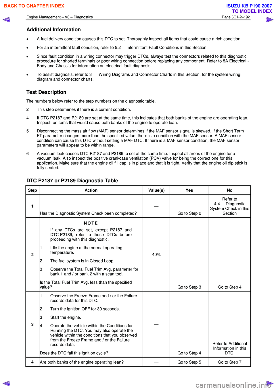
The numbers below refer to the step numbers on the diagnostic table.
2 This step determines if there is a current condition.
4 If DTC P2187 and P2189 are set at the same time, this indicates that both banks of the engine are operating lean. Inspect for items that would cause both banks of the engine to operate lean.
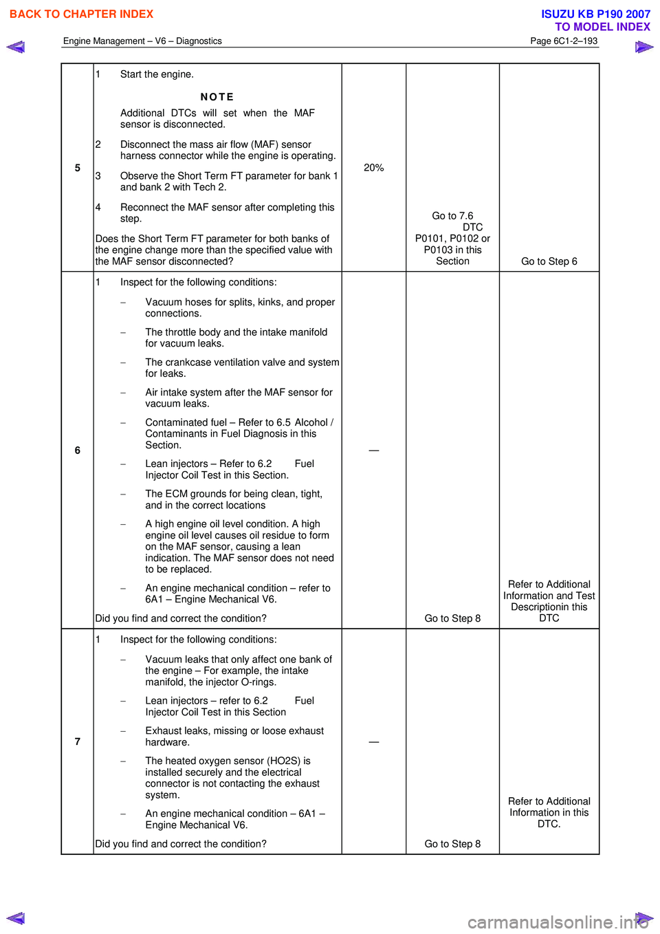
5 Disconnecting the mass air flow (MAF) sensor determines if the MAF sensor signal is skewed. If the Short Term FT parameter changes more than the specified value, there is a condition with the MAF sensor. A MAF sensor
condition can cause this DTC without setting a MAF DTC. If there is a MAF sensor condition, the MAF sensor
parameters will appear to be within range.
6 A vacuum leak causes DTC P2187 and P2189 to set at the same time. Inspect all areas of the engine for a vacuum leak. Also inspect the positive crankcase ventilation (PCV) valve for being the correct one for this
application. Make sure that the engine oil fill cap is in place and that it is tight. Verify that the engine oil dip stick is
fully seated.
DTC P2187 or P2189 Diagnostic Table
Step Action Value(s) Yes No
1
Has the Diagnostic System Check been completed? —
Go to Step 2 Refer to
4.4 Diagnostic
System Check in this Section
2 NOTE
If any DTCs are set, except P2187 and
DTC P2189, refer to those DTCs before
proceeding with this diagnostic.
1 Idle the engine at the normal operating temperature.
2 The fuel system is in Closed Loop.
3 Observe the Total Fuel Trim Avg. parameter for bank 1 and / or bank 2 with a scan tool.
Is the Total Fuel Trim Avg. less than the specified
value? 40%
Go to Step 3 Go to Step 4
3 1 Observe the Freeze Frame and / or the Failure
records data for this DTC.
2 Turn the ignition OFF for 30 seconds.
3 Start the engine.
4 Operate the vehicle within the Conditions for Running the DTC. You may also operate the
vehicle within the conditions that you observed
from the Freeze Frame and / or the Failure
records data.
Does the DTC fail this ignition cycle? —
Go to Step 4 Refer to Additional
Information in this DTC.
4 Are both banks of the engine operating lean? —
Go to Step 5 Go to Step 7
BACK TO CHAPTER INDEX
TO MODEL INDEX
ISUZU KB P190 2007
Page 3471 of 6020
Engine Management – V6 – Diagnostics Page 6C1-2–193
5 1 Start the engine.
NOTE
Additional DTCs will set when the MAF
sensor is disconnected.
2 Disconnect the mass air flow (MAF) sensor harness connector while the engine is operating.
3 Observe the Short Term FT parameter for bank 1 and bank 2 with Tech 2.
4 Reconnect the MAF sensor after completing this step.
Does the Short Term FT parameter for both banks of
the engine change more than the specified value with
the MAF sensor disconnected? 20%
Go to 7.6
DTC
P0101, P0102 or P0103 in this Section Go to Step 6
6 1 Inspect for the following conditions:
− Vacuum hoses for splits, kinks, and proper
connections.
− The throttle body and the intake manifold
for vacuum leaks.
− The crankcase ventilation valve and system
for leaks.
− Air intake system after the MAF sensor for
vacuum leaks.
− Contaminated fuel – Refer to 6.5 Alcohol /
Contaminants in Fuel Diagnosis in this
Section.
− Lean injectors – Refer to 6.2 Fuel
Injector Coil Test in this Section.
− The ECM grounds for being clean, tight,
and in the correct locations
− A high engine oil level condition. A high
engine oil level causes oil residue to form
on the MAF sensor, causing a lean
indication. The MAF sensor does not need
to be replaced.
− An engine mechanical condition – refer to
6A1 – Engine Mechanical V6.
Did you find and correct the condition? —
Go to Step 8 Refer to Additional
Information and Test Descriptionin this DTC
7 1 Inspect for the following conditions:
− Vacuum leaks that only affect one bank of
the engine – For example, the intake
manifold, the injector O-rings.
− Lean injectors – refer to 6.2 Fuel
Injector Coil Test in this Section
− Exhaust leaks, missing or loose exhaust
hardware.
− The heated oxygen sensor (HO2S) is
installed securely and the electrical
connector is not contacting the exhaust
system.
− An engine mechanical condition – 6A1 –
Engine Mechanical V6.
Did you find and correct the condition? —
Go to Step 8 Refer to Additional
Information in this DTC.
BACK TO CHAPTER INDEX
TO MODEL INDEX
ISUZU KB P190 2007
Page 3474 of 6020
Engine Management – V6 – Diagnostics Page 6C1-2–196
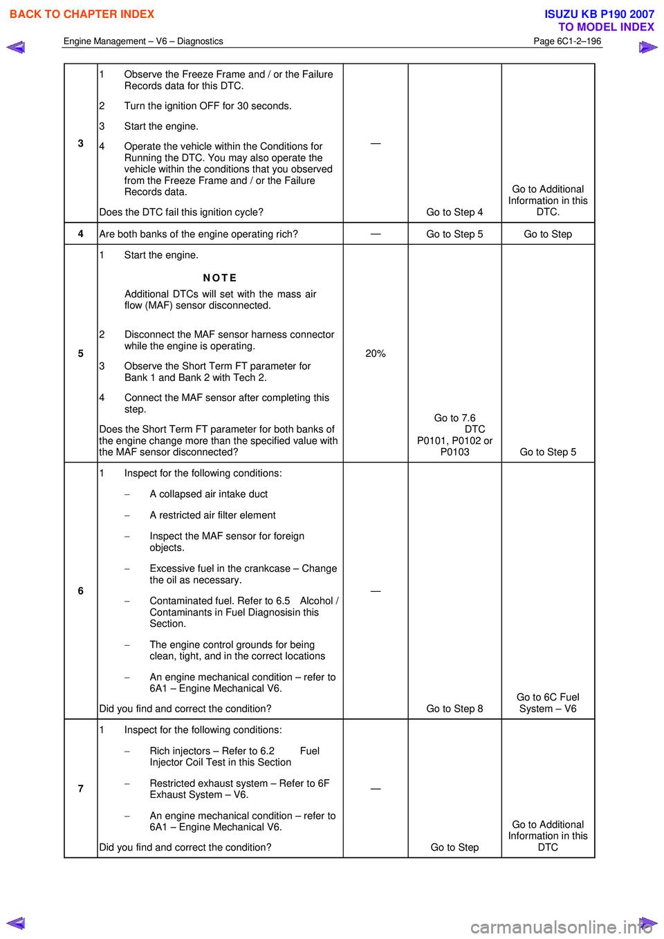
3 1 Observe the Freeze Frame and / or the Failure
Records data for this DTC.
2 Turn the ignition OFF for 30 seconds.
3 Start the engine.
4 Operate the vehicle within the Conditions for Running the DTC. You may also operate the
vehicle within the conditions that you observed
from the Freeze Frame and / or the Failure
Records data.
Does the DTC fail this ignition cycle? —
Go to Step 4 Go to Additional
Information in this DTC.
4 Are both banks of the engine operating rich? —
Go to Step 5 Go to Step
5 1 Start the engine.
NOTE
Additional DTCs will set with the mass air
flow (MAF) sensor disconnected.
2 Disconnect the MAF sensor harness connector while the engine is operating.
3 Observe the Short Term FT parameter for Bank 1 and Bank 2 with Tech 2.
4 Connect the MAF sensor after completing this step.
Does the Short Term FT parameter for both banks of
the engine change more than the specified value with
the MAF sensor disconnected? 20%
Go to 7.6
DTC
P0101, P0102 or P0103 Go to Step 5
6 1 Inspect for the following conditions:
− A collapsed air intake duct
− A restricted air filter element
− Inspect the MAF sensor for foreign
objects.
− Excessive fuel in the crankcase – Change
the oil as necessary.
− Contaminated fuel. Refer to 6.5 Alcohol /
Contaminants in Fuel Diagnosisin this
Section.
− The engine control grounds for being
clean, tight, and in the correct locations
− An engine mechanical condition – refer to
6A1 – Engine Mechanical V6.
Did you find and correct the condition? —
Go to Step 8 Go to 6C Fuel
System – V6
7 1 Inspect for the following conditions:
− Rich injectors – Refer to 6.2 Fuel
Injector Coil Test in this Section
− Restricted exhaust system – Refer to 6F
Exhaust System – V6.
− An engine mechanical condition – refer to
6A1 – Engine Mechanical V6.
Did you find and correct the condition? —
Go to Step Go to Additional
Information in this DTC
BACK TO CHAPTER INDEX
TO MODEL INDEX
ISUZU KB P190 2007
Page 3503 of 6020
Engine Management – V6 – Diagnostics Page 6C1-2–225
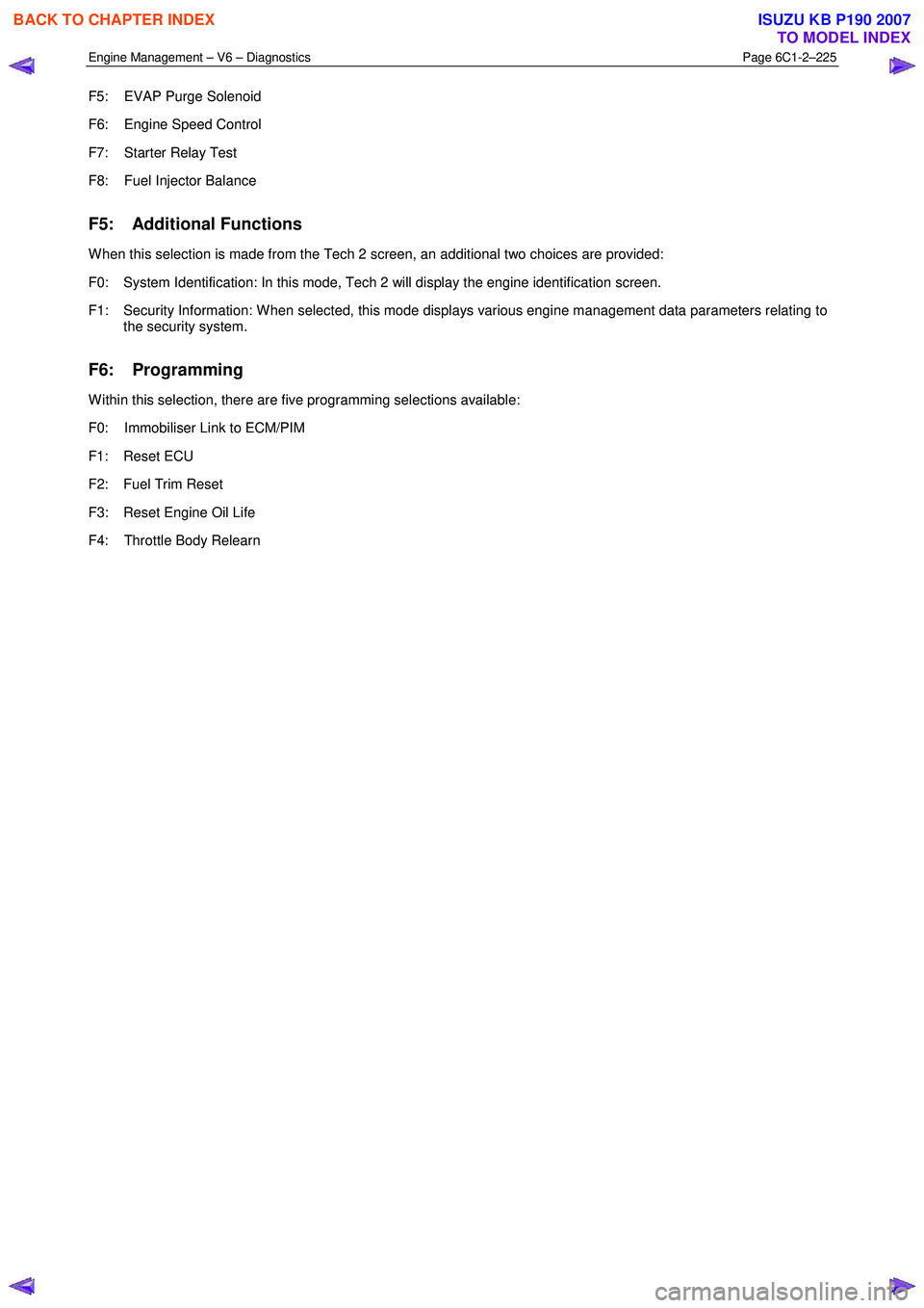
F5: EVAP Purge Solenoid
F6: Engine Speed Control
F7: Starter Relay Test
F8: Fuel Injector Balance
F5: Additional Functions
W hen this selection is made from the Tech 2 screen, an additional two choices are provided:
F0: System Identification: In this mode, Tech 2 will display the engine identification screen.
F1: Security Information: W hen selected, this mode displays various engine management data parameters relating to the security system.
F6: Programming
W ithin this selection, there are five programming selections available:
F0: Immobiliser Link to ECM/PIM
F1: Reset ECU
F2: Fuel Trim Reset
F3: Reset Engine Oil Life
F4: Throttle Body Relearn
BACK TO CHAPTER INDEX
TO MODEL INDEX
ISUZU KB P190 2007
Page 3514 of 6020
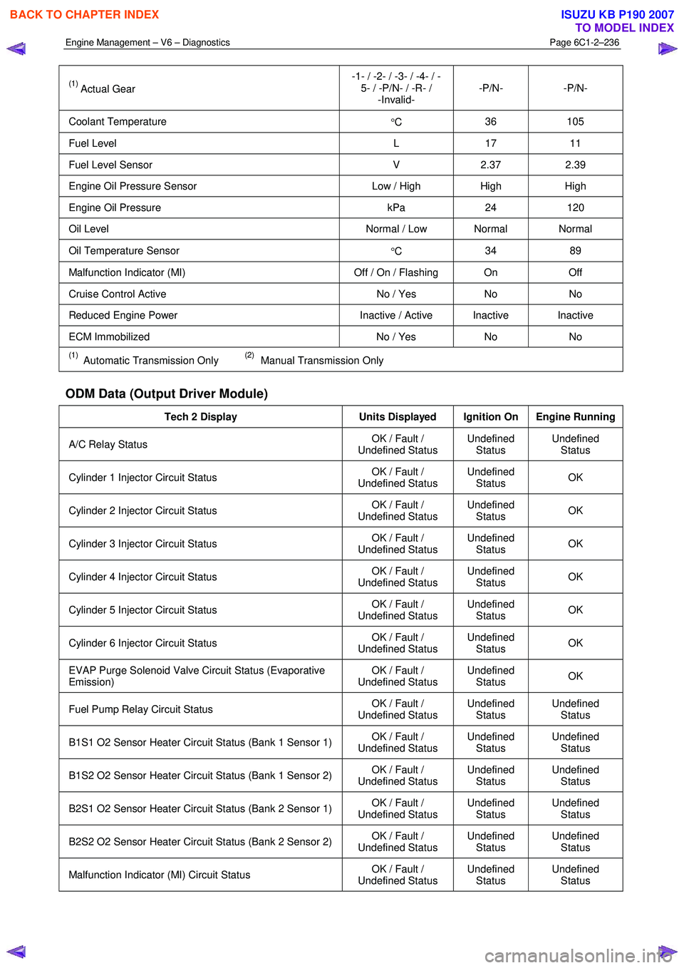
Engine Management – V6 – Diagnostics Page 6C1-2–236
(1) Actual Gear -1- / -2- / -3- / -4- / -
5- / -P/N- / -R- / -Invalid- -P/N- -P/N-
Coolant Temperature
°C 36 105
Fuel Level
L 17 11
Fuel Level Sensor V 2.37 2.39
Engine Oil Pressure Sensor Low / High High High
Engine Oil Pressure kPa 24 120
Oil Level Normal / Low Normal Normal
Oil Temperature Sensor
°C 34 89
Malfunction Indicator (MI)
Off / On / Flashing On Off
Cruise Control Active No / Yes No No
Reduced Engine Power Inactive / Active Inactive Inactive
ECM Immobilized No / Yes No No
(1) Automatic Transmission Only (2) Manual Transmission Only
ODM Data (Output Driver Module)
Tech 2 Display Units Displayed Ignition On Engine Running
A/C Relay Status OK / Fault /
Undefined Status Undefined
Status Undefined
Status
Cylinder 1 Injector Circuit Status OK / Fault /
Undefined Status Undefined
Status OK
Cylinder 2 Injector Circuit Status
OK / Fault /
Undefined Status Undefined
Status OK
Cylinder 3 Injector Circuit Status
OK / Fault /
Undefined Status Undefined
Status OK
Cylinder 4 Injector Circuit Status
OK / Fault /
Undefined Status Undefined
Status OK
Cylinder 5 Injector Circuit Status
OK / Fault /
Undefined Status Undefined
Status OK
Cylinder 6 Injector Circuit Status
OK / Fault /
Undefined Status Undefined
Status OK
EVAP Purge Solenoid Valve Circuit Status (Evaporative
Emission) OK / Fault /
Undefined Status Undefined
Status OK
Fuel Pump Relay Circuit Status
OK / Fault /
Undefined Status Undefined
Status Undefined
Status
B1S1 O2 Sensor Heater Circuit Status (Bank 1 Sensor 1) OK / Fault /
Undefined Status Undefined
Status Undefined
Status
B1S2 O2 Sensor Heater Circuit Status (Bank 1 Sensor 2) OK / Fault /
Undefined Status Undefined
Status Undefined
Status
B2S1 O2 Sensor Heater Circuit Status (Bank 2 Sensor 1) OK / Fault /
Undefined Status Undefined
Status Undefined
Status
B2S2 O2 Sensor Heater Circuit Status (Bank 2 Sensor 2) OK / Fault /
Undefined Status Undefined
Status Undefined
Status
Malfunction Indicator (MI) Circuit Status OK / Fault /
Undefined Status Undefined
Status Undefined
Status
BACK TO CHAPTER INDEX
TO MODEL INDEX
ISUZU KB P190 2007
Page 3515 of 6020
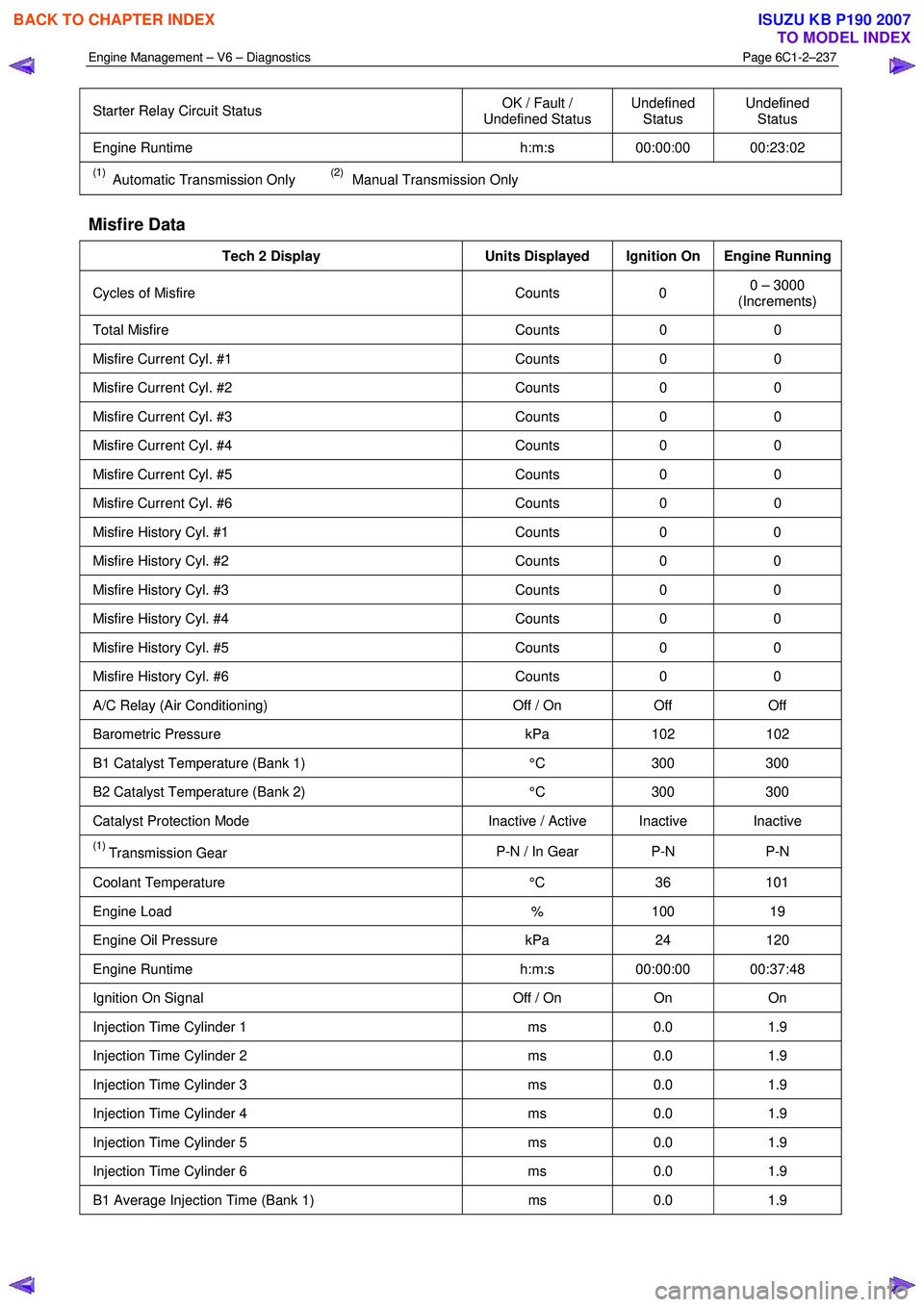
Engine Management – V6 – Diagnostics Page 6C1-2–237
Starter Relay Circuit Status OK / Fault /
Undefined Status Undefined
Status Undefined
Status
Engine Runtime h:m:s 00:00:00 00:23:02
(1) Automatic Transmission Only (2) Manual Transmission Only
Misfire Data
Tech 2 Display Units Displayed Ignition On Engine Running
Cycles of Misfire Counts 0 0 – 3000
(Increments)
Total Misfire Counts 0 0
Misfire Current Cyl. #1 Counts 0 0
Misfire Current Cyl. #2 Counts 0 0
Misfire Current Cyl. #3 Counts 0 0
Misfire Current Cyl. #4 Counts 0 0
Misfire Current Cyl. #5 Counts 0 0
Misfire Current Cyl. #6 Counts 0 0
Misfire History Cyl. #1 Counts 0 0
Misfire History Cyl. #2 Counts 0 0
Misfire History Cyl. #3 Counts 0 0
Misfire History Cyl. #4 Counts 0 0
Misfire History Cyl. #5 Counts 0 0
Misfire History Cyl. #6 Counts 0 0
A/C Relay (Air Conditioning) Off / On Off Off
Barometric Pressure kPa 102 102
B1 Catalyst Temperature (Bank 1) °C 300 300
B2 Catalyst Temperature (Bank 2) °C 300 300
Catalyst Protection Mode Inactive / Active Inactive Inactive
(1) Transmission Gear P-N / In Gear P-N P-N
Coolant Temperature
°C 36 101
Engine Load % 100 19
Engine Oil Pressure kPa 24 120
Engine Runtime h:m:s 00:00:00 00:37:48
Ignition On Signal Off / On On On
Injection Time Cylinder 1 ms 0.0 1.9
Injection Time Cylinder 2 ms 0.0 1.9
Injection Time Cylinder 3 ms 0.0 1.9
Injection Time Cylinder 4 ms 0.0 1.9
Injection Time Cylinder 5 ms 0.0 1.9
Injection Time Cylinder 6 ms 0.0 1.9
B1 Average Injection Time (Bank 1) ms 0.0 1.9
BACK TO CHAPTER INDEX
TO MODEL INDEX
ISUZU KB P190 2007
Page 3518 of 6020

Engine Management – V6 – Diagnostics Page 6C1-2–240
Cruise Control Switch: This parameter displays the state of the cruise control on/off switch input to the control module.
Cruise Control Disengagement Reason: The parameter displays which of a possible 28 causes for the cruise control
to disengage.
CC Disengagement 1 – 8 History (Cruise Control): The parameter displays the last 8 cruise control disengages in
order from 1 to 8, with 8 being the most recent. There are about 28 possible causes for the cruise control to disengage.
Cruise Resume/Acceleration Switch: This parameter displays the state of the cruise control resume/accel switch
position input to the ECM.
Cruise Set / Coast Switch: This parameter displays the state of the cruise controls set/decel. switch position input to
the ECM.
Cycles of Misfire: This parameter displays the number of misfire tests during 200 engine revolutions.
Cylinder 1 – 6 Injector Circuit Status: This parameter displays the state of the fuel injector control circuit. The
parameter displays ‘Fault’ if the fuel injector control circuit is open, shorted to ground, or shorted to voltage. This
parameter displays ‘Undefined Status’ until the control circuit has been commanded ‘On’.
Dec. Fuel Cutoff (Deceleration): This parameter displays the status of the ECM operating mode, used to turn off the
fuel injectors and the evaporative emission (EVAP) canister purge valve during certain deceleration conditions.
Desired Engine Idle Speed: This parameter displays the desired engine idle speed as commanded by the ECM.
Desired Throttle Position: This parameter displays the desired throttle position (TP) angle commanded by the ECM.
Distance Since DTC Cleared: This parameter displays the distance (km) travelled since any diagnostic trouble code
(DTC) has been cleared from the ECM memory.
DTC Set This Ignition: This parameter displays Yes if a DTC set on the current ignition cycle.
ECM Immobilized: This parameter displays ‘Yes’ when an internal control module reset occurs. Tech 2 will display ‘No’
under normal operating conditions.
Electronic Throttle Control Learn Counter: W hen the ECM performs a throttle body relearn procedure, the throttle
plate is commanded to move from the rest position (7% open) to full closed (0%), then to around 10% open.
At the start of this procedure, the Tech 2 ‘TAC Learn Counter’ parameter should display 0, then count up to 11 after the
procedure is completed. If the counter did not start at 0 or if the counter did not end at 11, a fault has occurred and a
DTC should set.
Engine Control Ignition Relay: This parameter displays the state of the control circuit for control module power relay
as commanded by the ECM.
Engine Control Ignition Relay Feedback: This parameter displays the voltage available at the engine control ignition
relay pin of the control module.
Engine Load: This parameter displays the calculated engine load in percent based on inputs to the control module from
various engine sensors.
Engine Oil Life Remaining: This parameter displays the percentage of engine oil life remaining. The controller
calculates the engine oil life by monitoring engine load, collant temperature and engine speed.
Engine Oil Pressure: This parameter displays the oil pressure in kPa from the ECM, developed from the engine oil
pressure (EOP) sensor input.
Engine Oil Pressure Sensor: This parameter displays ‘High’ if the engine oil pressure is within the correct range. If the
ECM detects that the engine oil pressure is not within the correct range, Tech 2 will display ‘Low’.
Engine Runtime: This parameter displays the time elapsed since the engine was started.
Engine Speed: This parameter displays the speed of the engine crankshaft rotation from information received from the
CKP sensor. If there is a CKP sensor DTC, the ECM calculates the engine speed from one of the camshaft position
(CMP) sensors.
EVAP Purge Solenoid (Evaporative Emission): This parameter displays the on-time or duty cycle of the EVAP
canister purge solenoid commanded by the ECM. Zero percent indicates no purge. One hundred percent indicates full
purge.
EVAP Purge Solenoid Valve Circuit Status (Evaporative Emission): This parameter displays the state of the EVAP
purge solenoid control circuit. The parameter displays ‘Fault’ if the EVAP purge solenoid control circuit is open, shorted
to ground, or shorted to voltage. The parameter displays ‘Undefined Status’ until the circuit has been established as
‘OK’.
Cooling Fan Relay: This parameter displays the control module commanded state of the fan relay control circuit.
BACK TO CHAPTER INDEX
TO MODEL INDEX
ISUZU KB P190 2007
Page 3519 of 6020
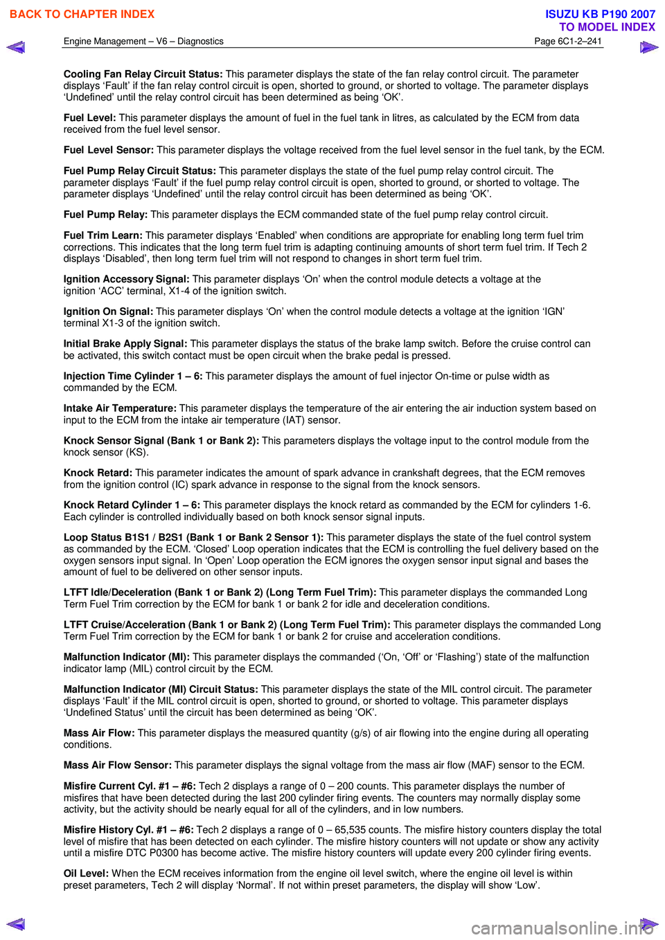
Engine Management – V6 – Diagnostics Page 6C1-2–241
Cooling Fan Relay Circuit Status: This parameter displays the state of the fan relay control circuit. The parameter
displays ‘Fault’ if the fan relay control circuit is open, shorted to ground, or shorted to voltage. The parameter displays
‘Undefined’ until the relay control circuit has been determined as being ‘OK’.
Fuel Level: This parameter displays the amount of fuel in the fuel tank in litres, as calculated by the ECM from data
received from the fuel level sensor.
Fuel Level Sensor: This parameter displays the voltage received from the fuel level sensor in the fuel tank, by the ECM.
Fuel Pump Relay Circuit Status: This parameter displays the state of the fuel pump relay control circuit. The
parameter displays ‘Fault’ if the fuel pump relay control circuit is open, shorted to ground, or shorted to voltage. The
parameter displays ‘Undefined’ until the relay control circuit has been determined as being ‘OK’.
Fuel Pump Relay: This parameter displays the ECM commanded state of the fuel pump relay control circuit.
Fuel Trim Learn: This parameter displays ‘Enabled’ when conditions are appropriate for enabling long term fuel trim
corrections. This indicates that the long term fuel trim is adapting continuing amounts of short term fuel trim. If Tech 2
displays ‘Disabled’, then long term fuel trim will not respond to changes in short term fuel trim.
Ignition Accessory Signal: This parameter displays ‘On’ when the control module detects a voltage at the
ignition ‘ACC’ terminal, X1-4 of the ignition switch.
Ignition On Signal: This parameter displays ‘On’ when the control module detects a voltage at the ignition ‘IGN’
terminal X1-3 of the ignition switch.
Initial Brake Apply Signal: This parameter displays the status of the brake lamp switch. Before the cruise control can
be activated, this switch contact must be open circuit when the brake pedal is pressed.
Injection Time Cylinder 1 – 6: This parameter displays the amount of fuel injector On-time or pulse width as
commanded by the ECM.
Intake Air Temperature: This parameter displays the temperature of the air entering the air induction system based on
input to the ECM from the intake air temperature (IAT) sensor.
Knock Sensor Signal (Bank 1 or Bank 2): This parameters displays the voltage input to the control module from the
knock sensor (KS).
Knock Retard: This parameter indicates the amount of spark advance in crankshaft degrees, that the ECM removes
from the ignition control (IC) spark advance in response to the signal from the knock sensors.
Knock Retard Cylinder 1 – 6: This parameter displays the knock retard as commanded by the ECM for cylinders 1-6.
Each cylinder is controlled individually based on both knock sensor signal inputs.
Loop Status B1S1 / B2S1 (Bank 1 or Bank 2 Sensor 1): This parameter displays the state of the fuel control system
as commanded by the ECM. ‘Closed’ Loop operation indicates that the ECM is controlling the fuel delivery based on the
oxygen sensors input signal. In ‘Open’ Loop operation the ECM ignores the oxygen sensor input signal and bases the
amount of fuel to be delivered on other sensor inputs.
LTFT Idle/Deceleration (Bank 1 or Bank 2) (Long Term Fuel Trim): This parameter displays the commanded Long
Term Fuel Trim correction by the ECM for bank 1 or bank 2 for idle and deceleration conditions.
LTFT Cruise/Acceleration (Bank 1 or Bank 2) (Long Term Fuel Trim): This parameter displays the commanded Long
Term Fuel Trim correction by the ECM for bank 1 or bank 2 for cruise and acceleration conditions.
Malfunction Indicator (MI): This parameter displays the commanded (‘On, ‘Off’ or ‘Flashing’) state of the malfunction
indicator lamp (MIL) control circuit by the ECM.
Malfunction Indicator (MI) Circuit Status: This parameter displays the state of the MIL control circuit. The parameter
displays ‘Fault’ if the MIL control circuit is open, shorted to ground, or shorted to voltage. This parameter displays
‘Undefined Status’ until the circuit has been determined as being ‘OK’.
Mass Air Flow: This parameter displays the measured quantity (g/s) of air flowing into the engine during all operating
conditions.
Mass Air Flow Sensor: This parameter displays the signal voltage from the mass air flow (MAF) sensor to the ECM.
Misfire Current Cyl. #1 – #6: Tech 2 displays a range of 0 – 200 counts. This parameter displays the number of
misfires that have been detected during the last 200 cylinder firing events. The counters may normally display some
activity, but the activity should be nearly equal for all of the cylinders, and in low numbers.
Misfire History Cyl. #1 – #6: Tech 2 displays a range of 0 – 65,535 counts. The misfire history counters display the total
level of misfire that has been detected on each cylinder. The misfire history counters will not update or show any activity
until a misfire DTC P0300 has become active. The misfire history counters will update every 200 cylinder firing events.
Oil Level: W hen the ECM receives information from the engine oil level switch, where the engine oil level is within
preset parameters, Tech 2 will display ‘Normal’. If not within preset parameters, the display will show ‘Low’.
BACK TO CHAPTER INDEX
TO MODEL INDEX
ISUZU KB P190 2007