2007 ISUZU KB P190 ignition
[x] Cancel search: ignitionPage 3325 of 6020
Engine Management – V6 – Diagnostics Page 6C1-2–47
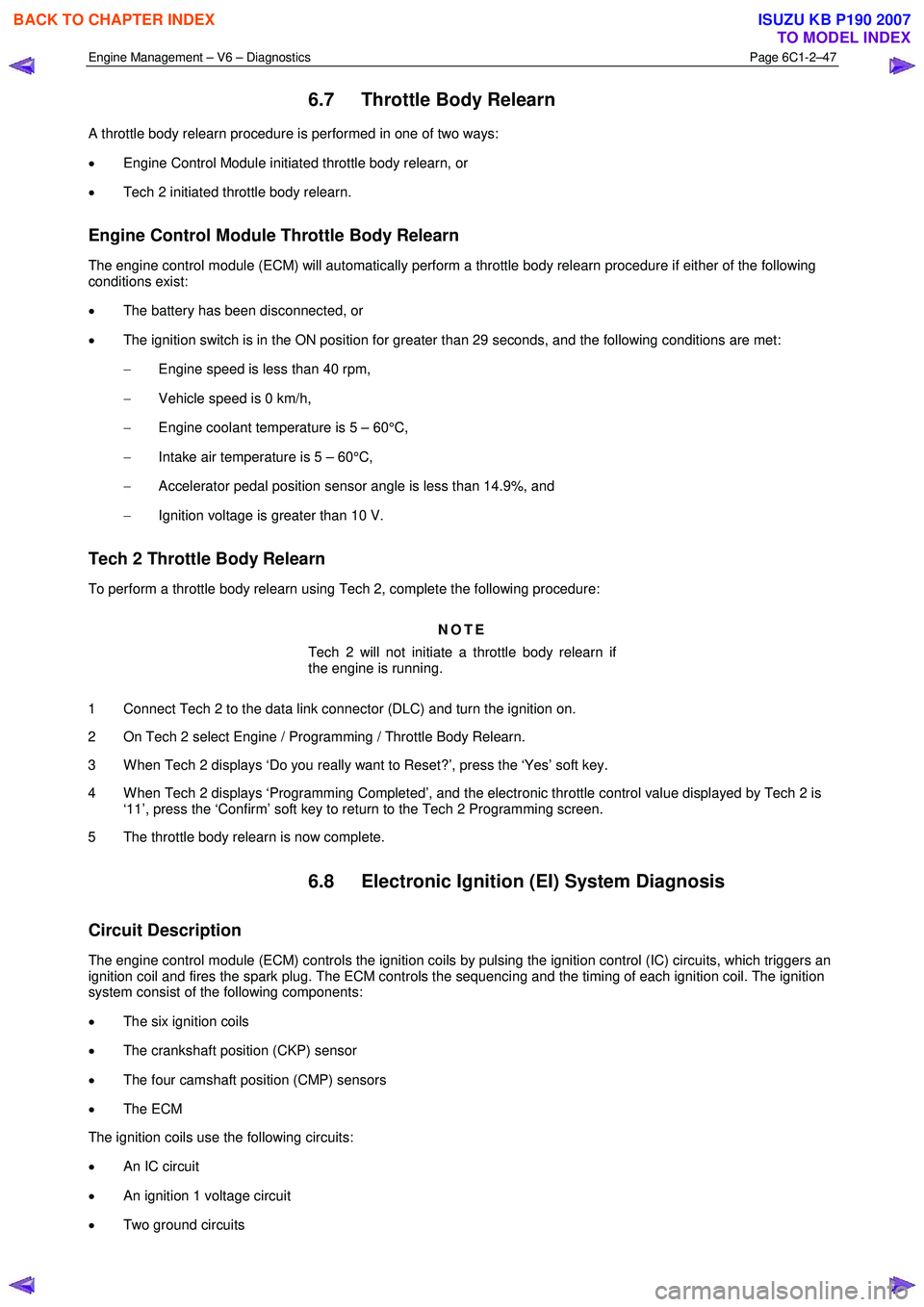
6.7 Throttle Body Relearn
A throttle body relearn procedure is performed in one of two ways:
• Engine Control Module initiated throttle body relearn, or
• Tech 2 initiated throttle body relearn.
Engine Control Module Throttle Body Relearn
The engine control module (ECM) will automatically perform a throttle body relearn procedure if either of the following
conditions exist:
• The battery has been disconnected, or
• The ignition switch is in the ON position for greater than 29 seconds, and the following conditions are met:
− Engine speed is less than 40 rpm,
− Vehicle speed is 0 km/h,
− Engine coolant temperature is 5 – 60°C,
− Intake air temperature is 5 – 60°C,
− Accelerator pedal position sensor angle is less than 14.9%, and
− Ignition voltage is greater than 10 V.
Tech 2 Throttle Body Relearn
To perform a throttle body relearn using Tech 2, complete the following procedure:
NOTE
Tech 2 will not initiate a throttle body relearn if
the engine is running.
1 Connect Tech 2 to the data link connector (DLC) and turn the ignition on.
2 On Tech 2 select Engine / Programming / Throttle Body Relearn.
3 W hen Tech 2 displays ‘Do you really want to Reset?’, press the ‘Yes’ soft key.
4 W hen Tech 2 displays ‘Programming Completed’, and the electronic throttle control value displayed by Tech 2 is ‘11’, press the ‘Confirm’ soft key to return to the Tech 2 Programming screen.
5 The throttle body relearn is now complete.
6.8 Electronic Ignition (EI) System Diagnosis
Circuit Description
The engine control module (ECM) controls the ignition coils by pulsing the ignition control (IC) circuits, which triggers an
ignition coil and fires the spark plug. The ECM controls the sequencing and the timing of each ignition coil. The ignition
system consist of the following components:
• The six ignition coils
• The crankshaft position (CKP) sensor
• The four camshaft position (CMP) sensors
• The ECM
The ignition coils use the following circuits:
• An IC circuit
• An ignition 1 voltage circuit
• Two ground circuits
BACK TO CHAPTER INDEX
TO MODEL INDEX
ISUZU KB P190 2007
Page 3326 of 6020
Engine Management – V6 – Diagnostics Page 6C1-2–48
Additional Information
• Use the J 35616-B Connector Test Adapter Kit for any test that requires probing the ECM harness connector or a
component harness connector.
• Inspect the ignition coils for aftermarket devices. An aftermarket device connected to the ignition coil circuits, may
cause a condition with the ignition coils.
• For an intermittent fault condition, refer to 5.2 Intermittent Fault Conditions in this Section.
• To assist diagnosis, refer to 3 W iring Diagrams and Connector Charts in this Section, for the system wiring
diagram and connector charts.
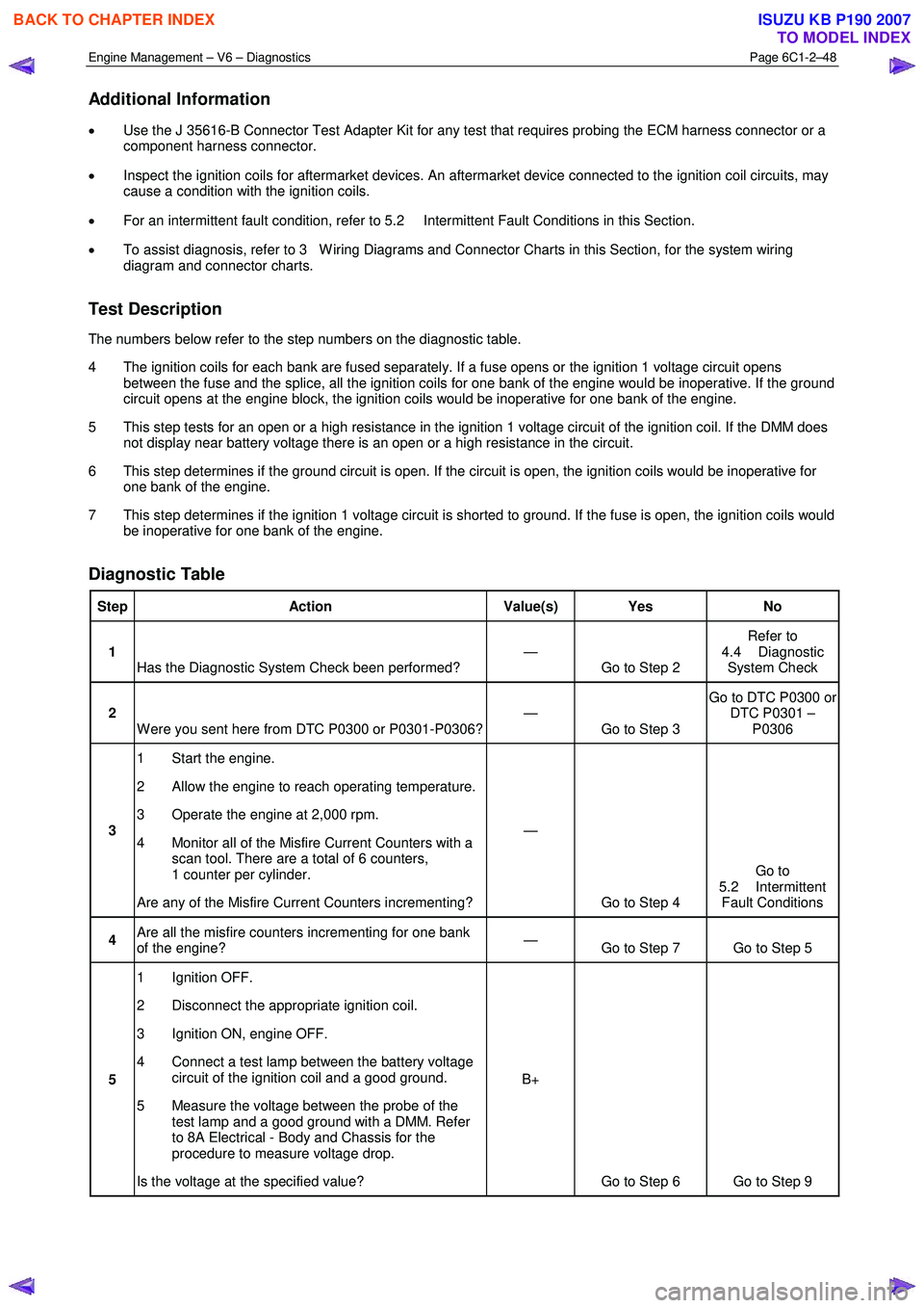
Test Description
The numbers below refer to the step numbers on the diagnostic table.
4 The ignition coils for each bank are fused separately. If a fuse opens or the ignition 1 voltage circuit opens between the fuse and the splice, all the ignition coils for one bank of the engine would be inoperative. If the ground
circuit opens at the engine block, the ignition coils would be inoperative for one bank of the engine.
5 This step tests for an open or a high resistance in the ignition 1 voltage circuit of the ignition coil. If the DMM does not display near battery voltage there is an open or a high resistance in the circuit.
6 This step determines if the ground circuit is open. If the circuit is open, the ignition coils would be inoperative for one bank of the engine.
7 This step determines if the ignition 1 voltage circuit is shorted to ground. If the fuse is open, the ignition coils would be inoperative for one bank of the engine.
Diagnostic Table
Step Action Value(s) Yes No
1
Has the Diagnostic System Check been performed? —
Go to Step 2 Refer to
4.4 Diagnostic System Check
2 W ere you sent here from DTC P0300 or P0301-P0306? —
Go to Step 3 Go to DTC P0300 or
DTC P0301 – P0306
3 1 Start the engine.
2 Allow the engine to reach operating temperature.
3 Operate the engine at 2,000 rpm.
4 Monitor all of the Misfire Current Counters with a scan tool. There are a total of 6 counters,
1 counter per cylinder.
Are any of the Misfire Current Counters incrementing? —
Go to Step 4 Go to
5.2 Intermittent Fault Conditions
4 Are all the misfire counters incrementing for one bank
of the engine? —
Go to Step 7 Go to Step 5
5 1 Ignition OFF.
2 Disconnect the appropriate ignition coil.
3 Ignition ON, engine OFF.
4 Connect a test lamp between the battery voltage circuit of the ignition coil and a good ground.
5 Measure the voltage between the probe of the test lamp and a good ground with a DMM. Refer
to 8A Electrical - Body and Chassis for the
procedure to measure voltage drop.
Is the voltage at the specified value? B+
Go to Step 6 Go to Step 9
BACK TO CHAPTER INDEX
TO MODEL INDEX
ISUZU KB P190 2007
Page 3327 of 6020

Engine Management – V6 – Diagnostics Page 6C1-2–49
6 1 Connect the test lamp between the battery
voltage circuit of the ignition coil and to each
ground circuit of the ignition coil.
Does the test lamp illuminate at each ground circuit? —
Go to Step 8 Go to Step 10
7 1 Test the battery voltage circuit for an open or high
resistance at the splice of the affected bank of
ignition coils. Refer to 8A Electrical - Body and
Chassis for circuit testing procedures.
Did you find and correct the condition? —
Go to Step 12 Go to Step 10
8 1 Test for an intermittent and for a poor connection
at the ignition coil. Refer to 8A Electrical - Body
and Chassis for circuit testing procedures.
Did you find and correct the condition? —
Go to Step 12 Go to Step 11
9 NOTE
The battery voltage circuit is shared with
other components. Disconnecting a
component on the shared battery voltage
circuit may isolate a shorted component.
Review the electrical schematic and
diagnose the shared circuits and
components.
1 Repair a short to ground, an open or high resistance in the ignition 1 voltage circuit. Refer to
Refer to 8A Electrical - Body and Chassis for
wiring repair procedures.
2 Replace the fuse as necessary.
Did you complete the repair? —
Go to Step 12 —
10 1 Repair the open or high resistance in the ground
circuit. Refer to 8A Electrical - Body and Chassis
for wiring repair procedures.
Did you complete the repair? —
Go to Step 12 —
11 1 Replace the ignition coil. Refer to 2.15 Ignition
Coils, in 6C1-3 Engine Management – V6 –
Service Operations.
Did you complete the replacement? —
Go to Step 12 —
12 1 Connect all disconnected components.
2 Use Tech 2 to clear the DTC/s.
3 Start the engine.
4 Observe the Capture Info with Tech 2.
Do any of the misfire counters increment? —
Go to Step 2 Go to Step 13
13 1 Using Tech 2, select the DTC display function.
Does Tech 2 display any DTCs? — Go to the
appropriate DTC
Table in this Section System OK
When all diagnosis and repairs are completed, clear all DTCs and verify correct operation
BACK TO CHAPTER INDEX
TO MODEL INDEX
ISUZU KB P190 2007
Page 3333 of 6020
Engine Management – V6 – Diagnostics Page 6C1-2–55
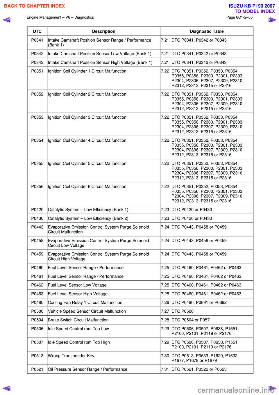
DTC Description Diagnostic Table
P0341 Intake Camshaft Position Sensor Range / Performance
(Bank 1) 7.21 DTC P0341, P0342 or P0343
P0342 Intake Camshaft Position Sensor Low Voltage (Bank 1) 7.21 DTC P0341, P0342 or P0343
P0343 Intake Camshaft Position Sensor High Voltage (Bank 1) 7.21 DTC P0341, P0342 or P0343
P0351 Ignition Coil Cylinder 1 Circuit Malfunction
7.22 DTC P0351, P0352, P0353, P0354,
P0355, P0356, P2300, P2301, P2303,
P2304, P2306, P2307, P2309, P2310,
P2312, P2313, P2315 or P2316
P0352 Ignition Coil Cylinder 2 Circuit Malfunction 7.22 DTC P0351, P0352, P0353, P0354,
P0355, P0356, P2300, P2301, P2303,
P2304, P2306, P2307, P2309, P2310,
P2312, P2313, P2315 or P2316
P0353 Ignition Coil Cylinder 3 Circuit Malfunction 7.22 DTC P0351, P0352, P0353, P0354,
P0355, P0356, P2300, P2301, P2303,
P2304, P2306, P2307, P2309, P2310,
P2312, P2313, P2315 or P2316
P0354 Ignition Coil Cylinder 4 Circuit Malfunction 7.22 DTC P0351, P0352, P0353, P0354,
P0355, P0356, P2300, P2301, P2303,
P2304, P2306, P2307, P2309, P2310,
P2312, P2313, P2315 or P2316
P0355 Ignition Coil Cylinder 5 Circuit Malfunction 7.22 DTC P0351, P0352, P0353, P0354,
P0355, P0356, P2300, P2301, P2303,
P2304, P2306, P2307, P2309, P2310,
P2312, P2313, P2315 or P2316
P0356 Ignition Coil Cylinder 6 Circuit Malfunction 7.22 DTC P0351, P0352, P0353, P0354,
P0355, P0356, P2300, P2301, P2303,
P2304, P2306, P2307, P2309, P2310,
P2312, P2313, P2315 or P2316
P0420 Catalytic System – Low Efficiency (Bank 1) 7.23 DTC P0420 or P0430
P0430 Catalytic System – Low Efficiency (Bank 2) 7.23 DTC P0420 or P0430
P0443 Evaporative Emission Control System Purge Solenoid
Circuit Malfunction 7.24 DTC P0443, P0458 or P0459
P0458 Evaporative Emission Control System Purge Solenoid
Circuit Low Voltage 7.24 DTC P0443, P0458 or P0459
P0459 Evaporative Emission Control System Purge Solenoid
Circuit High Voltage 7.24 DTC P0443, P0458 or P0459
P0460 Fuel Level Sensor Range / Performance
7.25 DTC P0460, P0461, P0462 or P0463
P0461 Fuel Level Sensor Range / Performance 7.25 DTC P0460, P0461, P0462 or P0463
P0462 Fuel Level Sensor Low Voltage 7.25 DTC P0460, P0461, P0462 or P0463
P0463 Fuel Level Sensor High Voltage 7.25 DTC P0460, P0461, P0462 or P0463
P0480 Cooling Fan Relay 1 Circuit Malfunction 7.26 DTC P0480, P0691 or P0692
P0500 Vehicle Speed Sensor Circuit Malfunction 7.27 DTC P0500
P0504 Brake Switch Circuit Malfunction 7.28 DTC P0504 or P0571
P0506 Idle Speed Control rpm Too Low 7.29 DTC P0506, P0507, P0638, P1551,
P2100, P2101, P2119 or P2176
P0507 Idle Speed Control rpm Too High 7.29 DTC P0506, P0507, P0638, P1551,
P2100, P2101, P2119 or P2176
P0513 W rong Transponder Key 7.30 DTC P0513, P0633, P1629, P1632,
P1677, P1678 or P1679
P0521 Oil Pressure Sensor Range / Performance 7.31 DTC P0521, P0522 or P0523
BACK TO CHAPTER INDEX
TO MODEL INDEX
ISUZU KB P190 2007
Page 3334 of 6020
Engine Management – V6 – Diagnostics Page 6C1-2–56
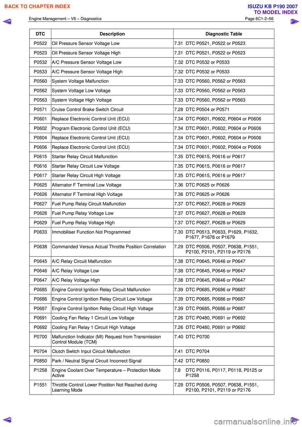
DTC Description Diagnostic Table
P0522 Oil Pressure Sensor Voltage Low 7.31 DTC P0521, P0522 or P0523
P0523 Oil Pressure Sensor Voltage High 7.31 DTC P0521, P0522 or P0523
P0532 A/C Pressure Sensor Voltage Low 7.32 DTC P0532 or P0533
P0533 A/C Pressure Sensor Voltage High 7.32 DTC P0532 or P0533
P0560 System Voltage Malfunction 7.33 DTC P0560, P0562 or P0563
P0562 System Voltage Low Voltage 7.33 DTC P0560, P0562 or P0563
P0563 System Voltage High Voltage 7.33 DTC P0560, P0562 or P0563
P0571 Cruise Control Brake Switch Circuit 7.28 DTC P0504 or P0571
P0601 Replace Electronic Control Unit (ECU) 7.34 DTC P0601, P0602, P0604 or P0606
P0602 Program Electronic Control Unit (ECU) 7.34 DTC P0601, P0602, P0604 or P0606
P0604 Replace Electronic Control Unit (ECU) 7.34 DTC P0601, P0602, P0604 or P0606
P0606 Replace Electronic Control Unit (ECU) 7.34 DTC P0601, P0602, P0604 or P0606
P0615 Starter Relay Circuit Malfunction 7.35 DTC P0615, P0616 or P0617
P0616 Starter Relay Circuit Low Voltage 7.35 DTC P0615, P0616 or P0617
P0617 Starter Relay Circuit High Voltage 7.35 DTC P0615, P0616 or P0617
P0625 Alternator F Terminal Low Voltage 7.36 DTC P0625 or P0626
P0626 Alternator F Terminal High Voltage 7.36 DTC P0625 or P0626
P0627 Fuel Pump Relay Circuit Malfunction 7.37 DTC P0627, P0628 or P0629
P0628 Fuel Pump Relay Voltage Low 7.37 DTC P0627, P0628 or P0629
P0629 Fuel Pump Relay Voltage High 7.37 DTC P0627, P0628 or P0629
P0633 Immobiliser Function Not Programmed 7.30 DTC P0513, P0633, P1629, P1632,
P1677, P1678 or P1679
P0638 Commanded Versus Actual Throttle Position Correlation 7.29 DTC P0506, P0507, P0638, P1551, P2100, P2101, P2119 or P2176
P0645 A/C Relay Circuit Malfunction 7.38 DTC P0645, P0646 or P0647
P0646 A/C Relay Voltage Low 7.38 DTC P0645, P0646 or P0647
P0647 A/C Relay Voltage High 7.38 DTC P0645, P0646 or P0647
P0685 Engine Control Ignition Relay Circuit Malfunction 7.39 DTC P0685, P0686 or P0687
P0686 Engine Control Ignition Relay Circuit Low Voltage 7.39 DTC P0685, P0686 or P0687
P0687 Engine Control Ignition Relay Circuit High Voltage 7.39 DTC P0685, P0686 or P0687
P0691 Cooling Fan Relay 1 Circuit Low Voltage 7.26 DTC P0480, P0691 or P0692
P0692 Cooling Fan Relay 1 Circuit High Voltage 7.26 DTC P0480, P0691 or P0692
P0700 Malfunction Indicator (MI) Request from Transmission
Control Module (TCM) 7.40 DTC P0700
P0704 Clutch Switch Input Circuit Malfunction
7.41 DTC P0704
P0850 Park / Neutral Signal Circuit Incorrect Signal 7.42 DTC P0850
P1258 Engine Coolant Over Temperature – Protection Mode
Active 7.8 DTC P0116, P0117, P0118, P0125 or
P1258
P1551 Throttle Control Lower Position Not Reached during Learning Mode 7.29 DTC P0506, P0507, P0638, P1551,
P2100, P2101, P2119 or P2176
BACK TO CHAPTER INDEX
TO MODEL INDEX
ISUZU KB P190 2007
Page 3337 of 6020
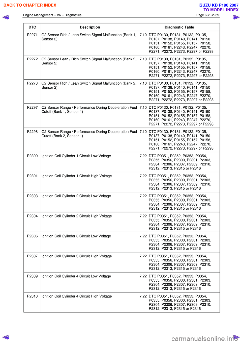
Engine Management – V6 – Diagnostics Page 6C1-2–59
DTC Description Diagnostic Table
P2271 O2 Sensor Rich / Lean Switch Signal Malfunction (Bank 1,
Sensor 2) 7.10 DTC P0130, P0131, P0132, P0135,
P0137, P0138, P0140, P0141, P0150
P0151, P0152, P0155, P0157, P0158,
P0160, P0161, P2243, P2247, P2270,
P2271, P2272, P2273, P2297 or P2298
P2272 O2 Sensor Lean / Rich Switch Signal Malfunction (Bank 2, Sensor 2) 7.10 DTC P0130, P0131, P0132, P0135,
P0137, P0138, P0140, P0141, P0150
P0151, P0152, P0155, P0157, P0158,
P0160, P0161, P2243, P2247, P2270,
P2271, P2272, P2273, P2297 or P2298
P2273 O2 Sensor Rich / Lean Switch Signal Malfunction (Bank 2, Sensor 2) 7.10 DTC P0130, P0131, P0132, P0135,
P0137, P0138, P0140, P0141, P0150
P0151, P0152, P0155, P0157, P0158,
P0160, P0161, P2243, P2247, P2270,
P2271, P2272, P2273, P2297 or P2298
P2297 O2 Sensor Range / Performance During Deceleration Fuel Cutoff (Bank 1, Sensor 1) 7.10 DTC P0130, P0131, P0132, P0135,
P0137, P0138, P0140, P0141, P0150
P0151, P0152, P0155, P0157, P0158,
P0160, P0161, P2243, P2247, P2270,
P2271, P2272, P2273, P2297 or P2298
P2298 O2 Sensor Range / Performance During Deceleration Fuel Cutoff (Bank 2, Sensor 1) 7.10 DTC P0130, P0131, P0132, P0135,
P0137, P0138, P0140, P0141, P0150
P0151, P0152, P0155, P0157, P0158,
P0160, P0161, P2243, P2247, P2270,
P2271, P2272, P2273, P2297 or P2298
P2300 Ignition Coil Cylinder 1 Circuit Low Voltage 7.22 DTC P0351, P0352, P0353, P0354,
P0355, P0356, P2300, P2301, P2303,
P2304, P2306, P2307, P2309, P2310,
P2312, P2313, P2315 or P2316
P2301 Ignition Coil Cylinder 1 Circuit High Voltage 7.22 DTC P0351, P0352, P0353, P0354,
P0355, P0356, P2300, P2301, P2303,
P2304, P2306, P2307, P2309, P2310,
P2312, P2313, P2315 or P2316
P2303 Ignition Coil Cylinder 2 Circuit Low Voltage 7.22 DTC P0351, P0352, P0353, P0354,
P0355, P0356, P2300, P2301, P2303,
P2304, P2306, P2307, P2309, P2310,
P2312, P2313, P2315 or P2316
P2304 Ignition Coil Cylinder 2 Circuit High Voltage 7.22 DTC P0351, P0352, P0353, P0354,
P0355, P0356, P2300, P2301, P2303,
P2304, P2306, P2307, P2309, P2310,
P2312, P2313, P2315 or P2316
P2306 Ignition Coil Cylinder 3 Circuit Low Voltage 7.22 DTC P0351, P0352, P0353, P0354,
P0355, P0356, P2300, P2301, P2303,
P2304, P2306, P2307, P2309, P2310,
P2312, P2313, P2315 or P2316
P2307 Ignition Coil Cylinder 3 Circuit High Voltage 7.22 DTC P0351, P0352, P0353, P0354,
P0355, P0356, P2300, P2301, P2303,
P2304, P2306, P2307, P2309, P2310,
P2312, P2313, P2315 or P2316
P2309 Ignition Coil Cylinder 4 Circuit Low Voltage 7.22 DTC P0351, P0352, P0353, P0354,
P0355, P0356, P2300, P2301, P2303,
P2304, P2306, P2307, P2309, P2310,
P2312, P2313, P2315 or P2316
P2310 Ignition Coil Cylinder 4 Circuit High Voltage 7.22 DTC P0351, P0352, P0353, P0354,
P0355, P0356, P2300, P2301, P2303,
P2304, P2306, P2307, P2309, P2310,
P2312, P2313, P2315 or P2316
BACK TO CHAPTER INDEX
TO MODEL INDEX
ISUZU KB P190 2007
Page 3338 of 6020
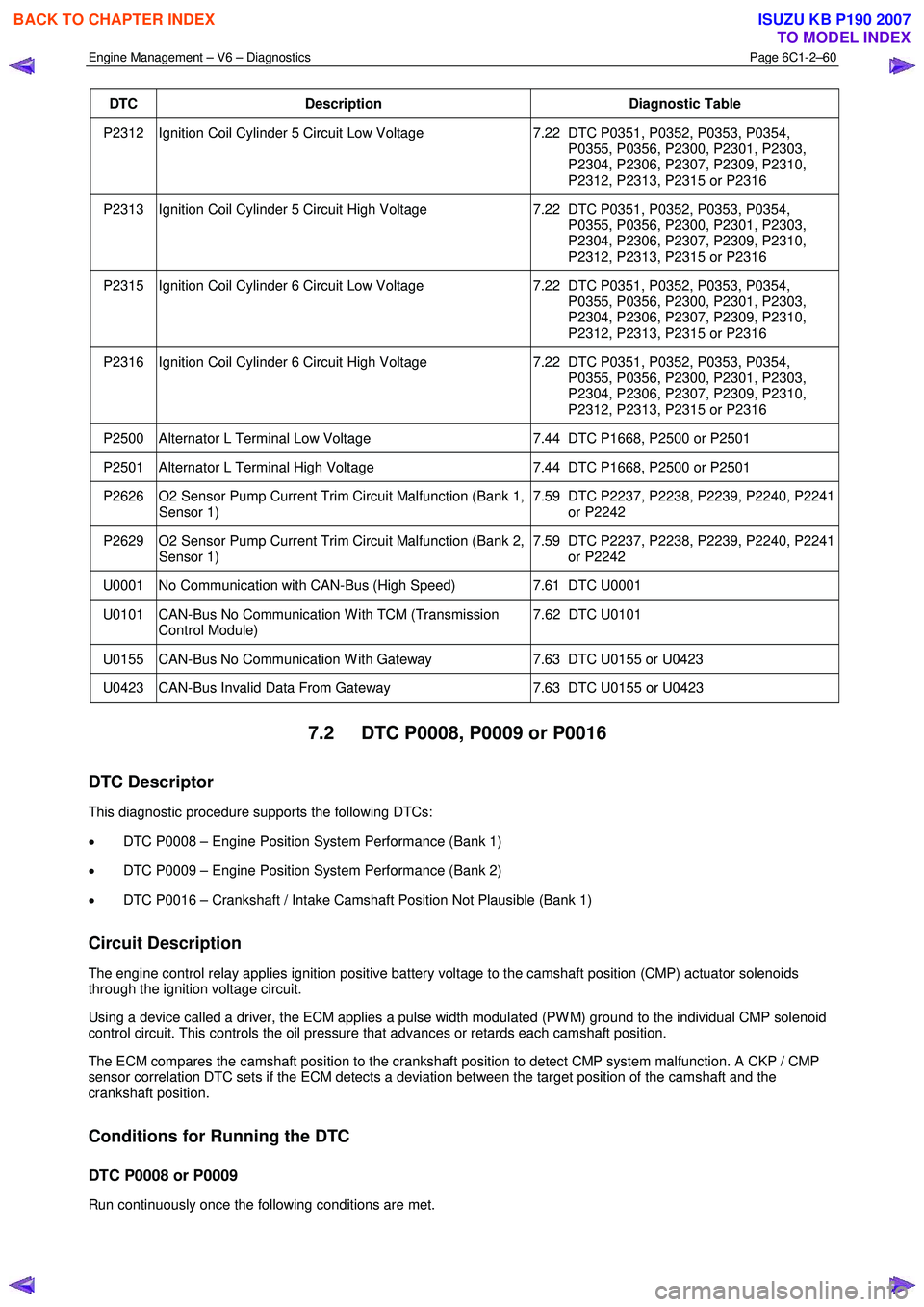
Engine Management – V6 – Diagnostics Page 6C1-2–60
DTC Description Diagnostic Table
P2312 Ignition Coil Cylinder 5 Circuit Low Voltage 7.22 DTC P0351, P0352, P0353, P0354,
P0355, P0356, P2300, P2301, P2303,
P2304, P2306, P2307, P2309, P2310,
P2312, P2313, P2315 or P2316
P2313 Ignition Coil Cylinder 5 Circuit High Voltage 7.22 DTC P0351, P0352, P0353, P0354,
P0355, P0356, P2300, P2301, P2303,
P2304, P2306, P2307, P2309, P2310,
P2312, P2313, P2315 or P2316
P2315 Ignition Coil Cylinder 6 Circuit Low Voltage 7.22 DTC P0351, P0352, P0353, P0354,
P0355, P0356, P2300, P2301, P2303,
P2304, P2306, P2307, P2309, P2310,
P2312, P2313, P2315 or P2316
P2316 Ignition Coil Cylinder 6 Circuit High Voltage 7.22 DTC P0351, P0352, P0353, P0354,
P0355, P0356, P2300, P2301, P2303,
P2304, P2306, P2307, P2309, P2310,
P2312, P2313, P2315 or P2316
P2500 Alternator L Terminal Low Voltage 7.44 DTC P1668, P2500 or P2501
P2501 Alternator L Terminal High Voltage 7.44 DTC P1668, P2500 or P2501
P2626 O2 Sensor Pump Current Trim Circuit Malfunction (Bank 1,
Sensor 1) 7.59 DTC P2237, P2238, P2239, P2240, P2241
or P2242
P2629 O2 Sensor Pump Current Trim Circuit Malfunction (Bank 2, Sensor 1) 7.59 DTC P2237, P2238, P2239, P2240, P2241
or P2242
U0001 No Communication with CAN-Bus (High Speed) 7.61 DTC U0001
U0101 CAN-Bus No Communication W ith TCM (Transmission
Control Module) 7.62 DTC U0101
U0155 CAN-Bus No Communication W ith Gateway
7.63 DTC U0155 or U0423
U0423 CAN-Bus Invalid Data From Gateway 7.63 DTC U0155 or U0423
7.2 DTC P0008, P0009 or P0016
DTC Descriptor
This diagnostic procedure supports the following DTCs:
• DTC P0008 – Engine Position System Performance (Bank 1)
• DTC P0009 – Engine Position System Performance (Bank 2)
• DTC P0016 – Crankshaft / Intake Camshaft Position Not Plausible (Bank 1)
Circuit Description
The engine control relay applies ignition positive battery voltage to the camshaft position (CMP) actuator solenoids
through the ignition voltage circuit.
Using a device called a driver, the ECM applies a pulse width modulated (PW M) ground to the individual CMP solenoid
control circuit. This controls the oil pressure that advances or retards each camshaft position.
The ECM compares the camshaft position to the crankshaft position to detect CMP system malfunction. A CKP / CMP
sensor correlation DTC sets if the ECM detects a deviation between the target position of the camshaft and the
crankshaft position.
Conditions for Running the DTC
DTC P0008 or P0009
Run continuously once the following conditions are met.
BACK TO CHAPTER INDEX
TO MODEL INDEX
ISUZU KB P190 2007
Page 3340 of 6020
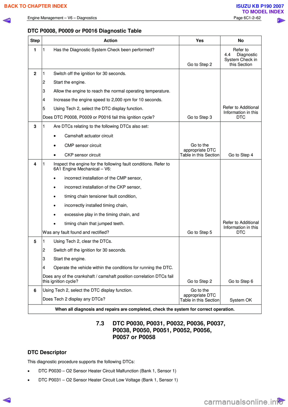
Engine Management – V6 – Diagnostics Page 6C1-2–62
DTC P0008, P0009 or P0016 Diagnostic Table
Step Action Yes No
1 1 Has the Diagnostic System Check been performed?
Go to Step 2 Refer to
4.4 Diagnostic
System Check in this Section
2 1 Switch off the ignition for 30 seconds.
2 Start the engine.
3 Allow the engine to reach the normal operating temperature.
4 Increase the engine speed to 2,000 rpm for 10 seconds.
5 Using Tech 2, select the DTC display function.
Does DTC P0008, P0009 or P0016 fail this ignition cycle? Go to Step 3 Refer to Additional
Information in this DTC
3 1 Are DTCs relating to the following DTCs also set:
• Camshaft actuator circuit
• CMP sensor circuit
• CKP sensor circuit Go to the
appropriate DTC
Table in this Section Go to Step 4
4 1 Inspect the engine for the following fault conditions. Refer to
6A1 Engine Mechanical – V6:
• incorrect installation of the CMP sensor,
• incorrect installation of the CKP sensor,
• timing chain tensioner fault condition,
• incorrectly installed timing chain,
• excessive play in the timing chain, and
• timing chain that jumped teeth.
W as any fault found and rectified? Go to Step 5 Refer to Additional
Information in this DTC
5 1 Using Tech 2, clear the DTCs.
2 Switch off the ignition for 30 seconds.
3 Start the engine.
4 Operate the vehicle within the conditions for running the DTC.
Does any of the crankshaft / camshaft position correlation DTCs fail
this ignition cycle? Go to Step 2 Go to Step 6
6 Using Tech 2, select the DTC display function.
Does Tech 2 display any DTCs? Go to the
appropriate DTC
Table in this Section System OK
When all diagnosis and repairs are completed, check the system for correct operation.
7.3 DTC P0030, P0031, P0032, P0036, P0037,
P0038, P0050, P0051, P0052, P0056,
P0057 or P0058
DTC Descriptor
This diagnostic procedure supports the following DTCs:
• DTC P0030 – O2 Sensor Heater Circuit Malfunction (Bank 1, Sensor 1)
• DTC P0031 – O2 Sensor Heater Circuit Low Voltage (Bank 1, Sensor 1)
BACK TO CHAPTER INDEX
TO MODEL INDEX
ISUZU KB P190 2007