2007 ISUZU KB P190 ignition
[x] Cancel search: ignitionPage 3312 of 6020
Engine Management – V6 – Diagnostics Page 6C1-2–34
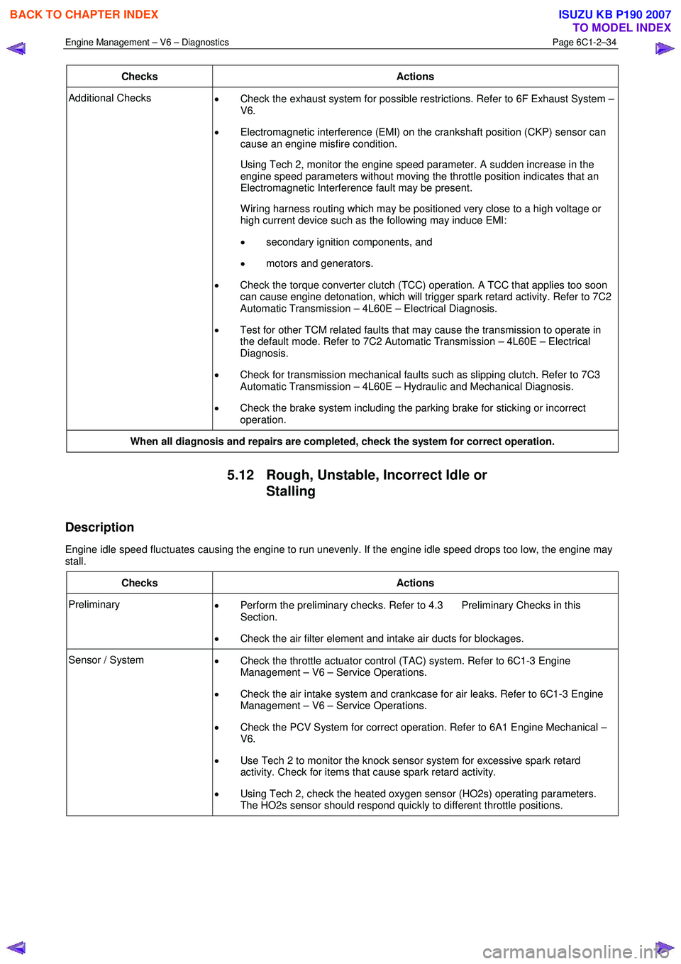
Checks Actions
Additional Checks
• Check the exhaust system for possible restrictions. Refer to 6F Exhaust System –
V6.
• Electromagnetic interference (EMI) on the crankshaft position (CKP) sensor can
cause an engine misfire condition.
Using Tech 2, monitor the engine speed parameter. A sudden increase in the engine speed parameters without moving the throttle position indicates that an
Electromagnetic Interference fault may be present.
W iring harness routing which may be positioned very close to a high voltage or high current device such as the following may induce EMI:
• secondary ignition components, and
• motors and generators.
• Check the torque converter clutch (TCC) operation. A TCC that applies too soon
can cause engine detonation, which will trigger spark retard activity. Refer to 7C2
Automatic Transmission – 4L60E – Electrical Diagnosis.
• Test for other TCM related faults that may cause the transmission to operate in
the default mode. Refer to 7C2 Automatic Transmission – 4L60E – Electrical
Diagnosis.
• Check for transmission mechanical faults such as slipping clutch. Refer to 7C3
Automatic Transmission – 4L60E – Hydraulic and Mechanical Diagnosis.
• Check the brake system including the parking brake for sticking or incorrect
operation.
When all diagnosis and repairs are completed, check the system for correct operation.
5.12 Rough, Unstable, Incorrect Idle or
Stalling
Description
Engine idle speed fluctuates causing the engine to run unevenly. If the engine idle speed drops too low, the engine may
stall.
Checks Actions
Preliminary • Perform the preliminary checks. Refer to 4.3 Preliminary Checks in this
Section.
• Check the air filter element and intake air ducts for blockages.
Sensor / System
• Check the throttle actuator control (TAC) system. Refer to 6C1-3 Engine
Management – V6 – Service Operations.
• Check the air intake system and crankcase for air leaks. Refer to 6C1-3 Engine
Management – V6 – Service Operations.
• Check the PCV System for correct operation. Refer to 6A1 Engine Mechanical –
V6.
• Use Tech 2 to monitor the knock sensor system for excessive spark retard
activity. Check for items that cause spark retard activity.
• Using Tech 2, check the heated oxygen sensor (HO2s) operating parameters.
The HO2s sensor should respond quickly to different throttle positions.
BACK TO CHAPTER INDEX
TO MODEL INDEX
ISUZU KB P190 2007
Page 3313 of 6020
Engine Management – V6 – Diagnostics Page 6C1-2–35
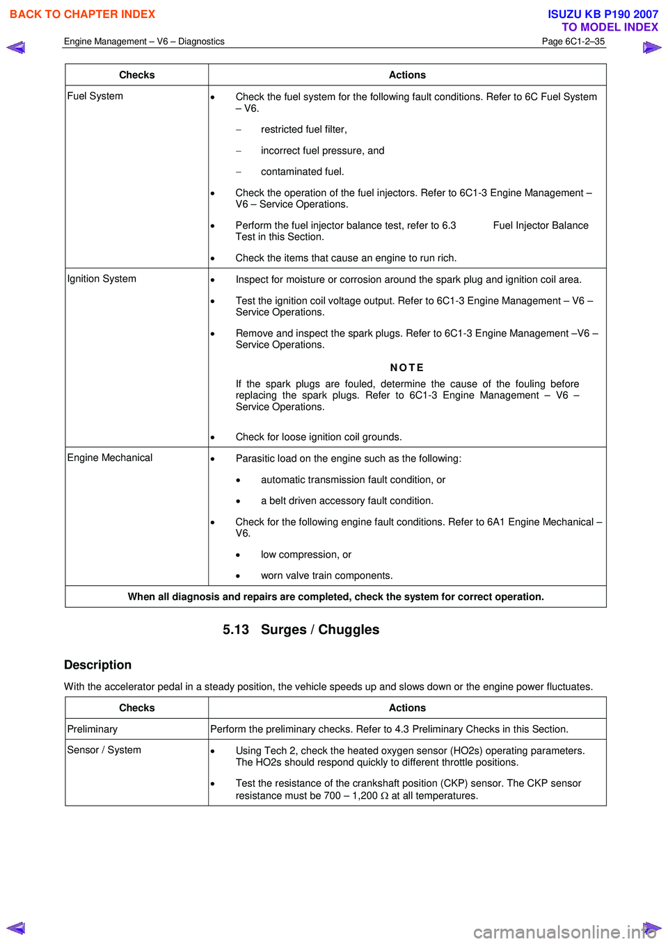
Checks Actions
Fuel System
• Check the fuel system for the following fault conditions. Refer to 6C Fuel System
– V6.
− restricted fuel filter,
− incorrect fuel pressure, and
− contaminated fuel.
• Check the operation of the fuel injectors. Refer to 6C1-3 Engine Management –
V6 – Service Operations.
• Perform the fuel injector balance test, refer to 6.3 Fuel Injector Balance
Test in this Section.
• Check the items that cause an engine to run rich.
Ignition System
• Inspect for moisture or corrosion around the spark plug and ignition coil area.
• Test the ignition coil voltage output. Refer to 6C1-3 Engine Management – V6 –
Service Operations.
• Remove and inspect the spark plugs. Refer to 6C1-3 Engine Management –V6 –
Service Operations.
NOTE
If the spark plugs are fouled, determine the cause of the fouling before
replacing the spark plugs. Refer to 6C1-3 Engine Management – V6 –
Service Operations.
• Check for loose ignition coil grounds.
Engine Mechanical
• Parasitic load on the engine such as the following:
• automatic transmission fault condition, or
• a belt driven accessory fault condition.
• Check for the following engine fault conditions. Refer to 6A1 Engine Mechanical –
V6.
• low compression, or
• worn valve train components.
When all diagnosis and repairs are completed, check the system for correct operation.
5.13 Surges / Chuggles
Description
W ith the accelerator pedal in a steady position, the vehicle speeds up and slows down or the engine power fluctuates.
Checks Actions
Preliminary Perform the preliminary checks. Refer to 4.3 Preliminary Checks in this Section.
Sensor / System
• Using Tech 2, check the heated oxygen sensor (HO2s) operating parameters.
The HO2s should respond quickly to different throttle positions.
• Test the resistance of the crankshaft position (CKP) sensor. The CKP sensor
resistance must be 700 – 1,200 Ω at all temperatures.
BACK TO CHAPTER INDEX
TO MODEL INDEX
ISUZU KB P190 2007
Page 3314 of 6020
Engine Management – V6 – Diagnostics Page 6C1-2–36
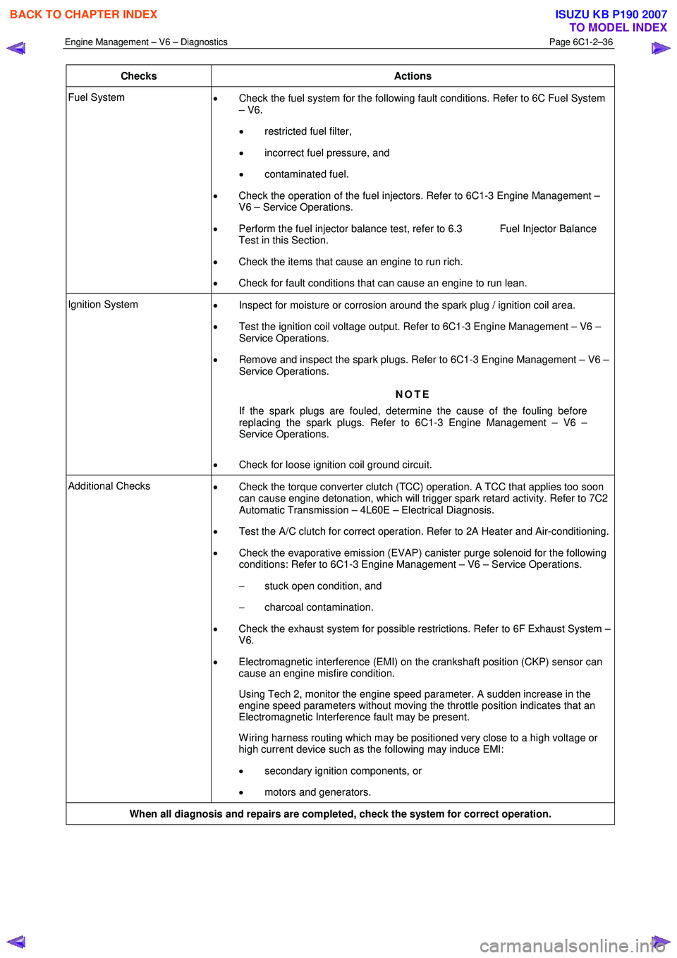
Checks Actions
Fuel System
• Check the fuel system for the following fault conditions. Refer to 6C Fuel System
– V6.
• restricted fuel filter,
• incorrect fuel pressure, and
• contaminated fuel.
• Check the operation of the fuel injectors. Refer to 6C1-3 Engine Management –
V6 – Service Operations.
• Perform the fuel injector balance test, refer to 6.3 Fuel Injector Balance
Test in this Section.
• Check the items that cause an engine to run rich.
• Check for fault conditions that can cause an engine to run lean.
Ignition System
• Inspect for moisture or corrosion around the spark plug / ignition coil area.
• Test the ignition coil voltage output. Refer to 6C1-3 Engine Management – V6 –
Service Operations.
• Remove and inspect the spark plugs. Refer to 6C1-3 Engine Management – V6 –
Service Operations.
NOTE
If the spark plugs are fouled, determine the cause of the fouling before
replacing the spark plugs. Refer to 6C1-3 Engine Management – V6 –
Service Operations.
• Check for loose ignition coil ground circuit.
Additional Checks
• Check the torque converter clutch (TCC) operation. A TCC that applies too soon
can cause engine detonation, which will trigger spark retard activity. Refer to 7C2
Automatic Transmission – 4L60E – Electrical Diagnosis.
• Test the A/C clutch for correct operation. Refer to 2A Heater and Air-conditioning.
• Check the evaporative emission (EVAP) canister purge solenoid for the following
conditions: Refer to 6C1-3 Engine Management – V6 – Service Operations.
− stuck open condition, and
− charcoal contamination.
• Check the exhaust system for possible restrictions. Refer to 6F Exhaust System –
V6.
• Electromagnetic interference (EMI) on the crankshaft position (CKP) sensor can
cause an engine misfire condition.
Using Tech 2, monitor the engine speed parameter. A sudden increase in the engine speed parameters without moving the throttle position indicates that an
Electromagnetic Interference fault may be present.
W iring harness routing which may be positioned very close to a high voltage or high current device such as the following may induce EMI:
• secondary ignition components, or
• motors and generators.
When all diagnosis and repairs are completed, check the system for correct operation.
BACK TO CHAPTER INDEX
TO MODEL INDEX
ISUZU KB P190 2007
Page 3315 of 6020
Engine Management – V6 – Diagnostics Page 6C1-2–37
6 Functional Checks
6.1 General Information
The items detailed in the following pages are to be used when there is a customer complaint and there are no diagnostic
trouble codes set, or one or more of the Tech 2 data values are not within the typical values. They are also to be used
when instructed from a DTC table. Before using these tables, you should refer to 5 Symptoms Diagnostics in this
Section, which may direct you to using the following functional checks.
The purpose of these tables is to diagnose engine control module (ECM) controlled components or sub-systems that do
not have diagnostic trouble codes assigned to them. Another purpose of these tables is for Technicians who feel
confident that a particular part of the sub-system is not operating properly and wants only to check that particular item
for proper operation without going through lengthy diagnostic procedures.
6.2 Fuel Injector Coil Test
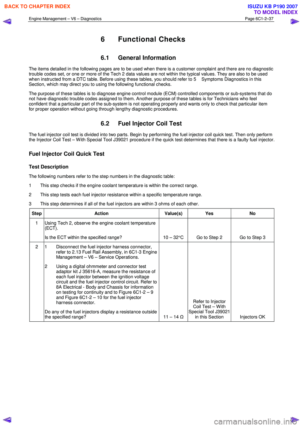
The fuel injector coil test is divided into two parts. Begin by performing the fuel injector coil quick test. Then only perform
the Injector Coil Test – W ith Special Tool J39021 procedure if the quick test determines that there is a faulty fuel injector.
Fuel Injector Coil Quick Test
Test Description
The following numbers refer to the step numbers in the diagnostic table:
1 This step checks if the engine coolant temperature is within the correct range.
2 This step tests each fuel injector resistance within a specific temperature range.
3 This step determines if all of the fuel injectors are within 3 ohms of each other.
Step Action Value(s) Yes No
1 Using Tech 2, observe the engine coolant temperature
(ECT).
Is the ECT within the specified range? 10 – 32 °C Go to Step 2 Go to Step 3
2 1 Disconnect the fuel injector harness connector,
refer to 2.13 Fuel Rail Assembly, in 6C1-3 Engine
Management – V6 – Service Operations.
2 Using a digital ohmmeter and connector test adaptor kit J 35616-A, measure the resistance of
each fuel injector between the ignition voltage
circuit and the fuel injector control circuit. Refer to
8A Electrical - Body and Chassis for information
on testing for continuity and to Figure 6C1-2 – 9
and Figure 6C1-2 – 10 for the fuel injector
harness connector.
Do any of the fuel injectors display a resistance outside
the specified range? 11 – 14 ΩRefer to Injector
Coil Test – W ith
Special Tool J39021 in this Section Injectors OK
BACK TO CHAPTER INDEX
TO MODEL INDEX
ISUZU KB P190 2007
Page 3316 of 6020
Engine Management – V6 – Diagnostics Page 6C1-2–38
Step Action Value(s) Yes No
3 1 Disconnect the fuel injector harness connector,
refer to 2.13 Fuel Rail Assembly, in 6C1-3 Engine
Management – V6 – Service Operations.
2 Using a digital ohmmeter and connector test adaptor kit J 35616-A, measure the resistance of
each fuel injector between the ignition voltage
circuit and the fuel injector control circuit. Refer to
8A Electrical - Body and Chassis for information
on testing for continuity and to Figure 6C1-2 – 9
and Figure 6C1-2 – 10 for the fuel injector
harness connector.
3 Record each fuel injector value.
4 Subtract the lowest resistance value from the highest.
Is the difference equal to, or less than, the specified
value? 3
Ω
Injectors OK Refer to Injector
Coil Test – W ith
Special Tool J39021 in this Section.
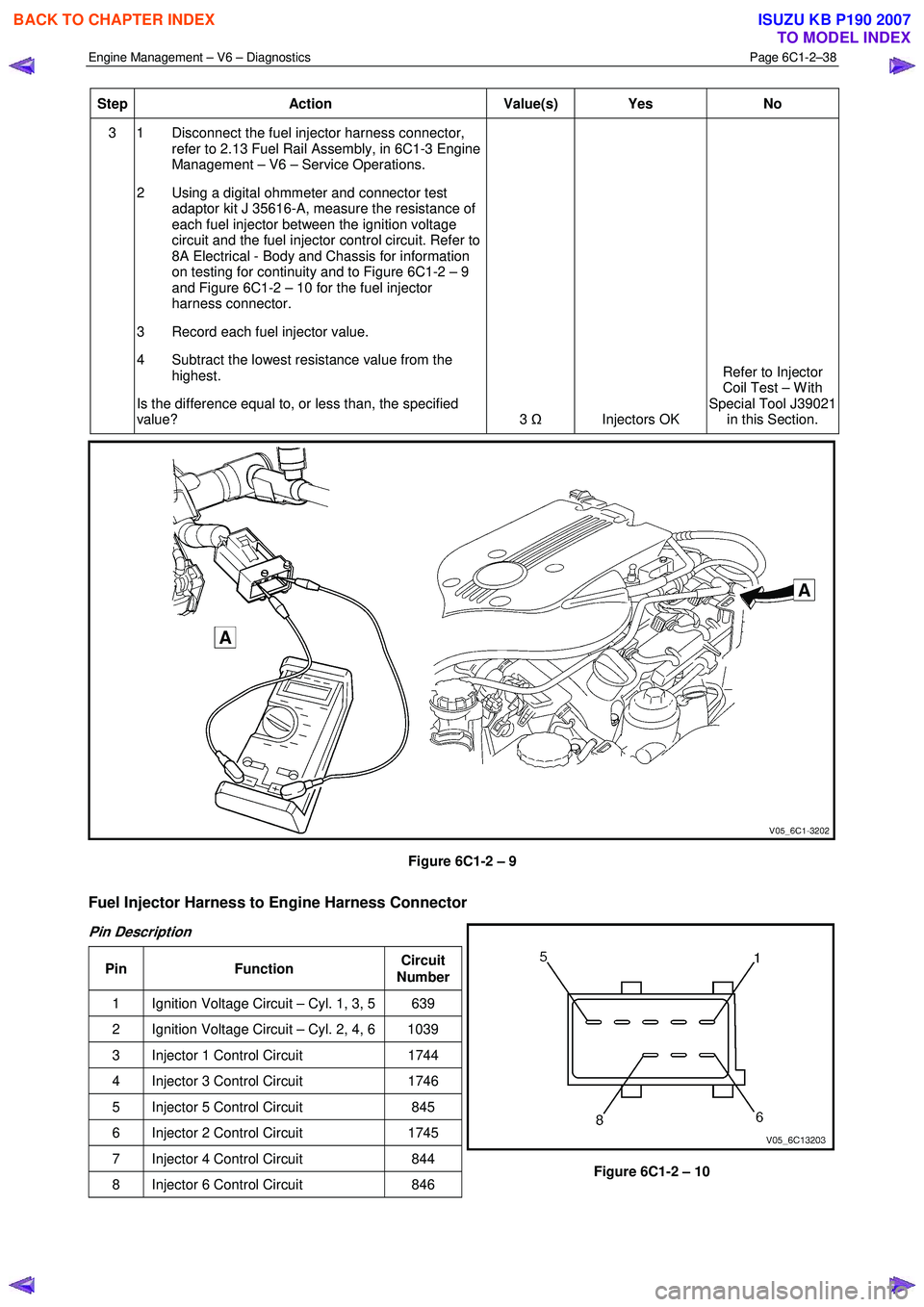
Figure 6C1-2 – 9
Fuel Injector Harness to Engine Harness Connector
Pin Description
Pin Function Circuit
Number
1 Ignition Voltage Circuit – Cyl. 1, 3, 5 639
2 Ignition Voltage Circuit – Cyl. 2, 4, 6 1039
3 Injector 1 Control Circuit 1744
4 Injector 3 Control Circuit 1746
5 Injector 5 Control Circuit 845
6 Injector 2 Control Circuit 1745
7 Injector 4 Control Circuit 844
8 Injector 6 Control Circuit 846
Figure 6C1-2 – 10
BACK TO CHAPTER INDEX
TO MODEL INDEX
ISUZU KB P190 2007
Page 3317 of 6020
Engine Management – V6 – Diagnostics Page 6C1-2–39
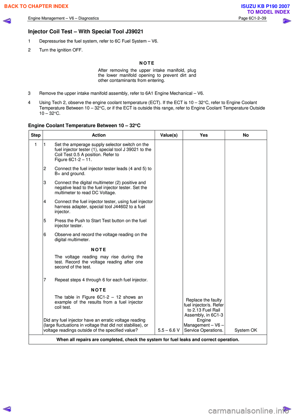
Injector Coil Test – With Special Tool J39021
1 Depressurise the fuel system, refer to 6C Fuel System – V6.
2 Turn the ignition OFF.
NOTE
After removing the upper intake manifold, plug
the lower manifold opening to prevent dirt and
other contaminants from entering.
3 Remove the upper intake manifold assembly, refer to 6A1 Engine Mechanical – V6.
4 Using Tech 2, observe the engine coolant temperature (ECT). If the ECT is 10 – 32 °C, refer to Engine Coolant
Temperature Between 10 – 32 °C, or if the ECT is outside this range, refer to Engine Coolant Temperature Outside
10 – 32 °C.
Engine Coolant Temperature Between 10 – 32 °
°°
°
C
Step Action Value(s) Yes No
1 1 Set the amperage supply selector switch on the
fuel injector tester (1), special tool J 39021 to the
Coil Test 0.5 A position. Refer to
Figure 6C1-2 – 11.
2 Connect the fuel injector tester leads (4 and 5) to B+ and ground.
3 Connect the digital multimeter (2) positive and negative lead to the fuel injector tester. Set the
multimeter to read DC Voltage.
4 Connect the fuel injector tester, using fuel injector harness adapter, special tool J44602 to a fuel
injector.
5 Press the Push to Start Test button on the fuel injector tester.
6 Observe and record the voltage reading on the digital multimeter.
NOTE
The voltage reading may rise during the
test. Record the voltage reading after one
second of the test.
7 Repeat steps 4 through 6 for each fuel injector. NOTE
The table in Figure 6C1-2 – 12 shows an
example of the results from a fuel injector
coil test.
Did any fuel injector have an erratic voltage reading
(large fluctuations in voltage that did not stabilise), or
voltage readings outside of the specified value? 5.5 – 6.6 V Replace the faulty
fuel injector/s. Refer to 2.13 Fuel Rail
Assembly, in 6C1-3 Engine
Management – V6 – Service Operations. System OK
When all repairs are completed, check the system for fuel leaks and correct operation.
BACK TO CHAPTER INDEX
TO MODEL INDEX
ISUZU KB P190 2007
Page 3320 of 6020
Engine Management – V6 – Diagnostics Page 6C1-2–42
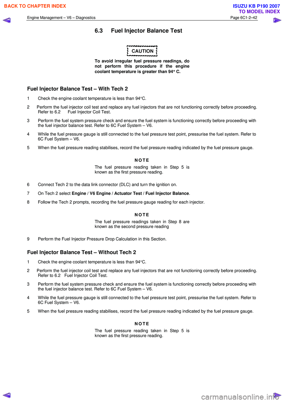
6.3 Fuel Injector Balance Test
To avoid irregular fuel pressure readings, do
not perform this procedure if the engine
coolant temperature is greater than 94 °
°°
°
C.
Fuel Injector Balance Test – With Tech 2
1 Check the engine coolant temperature is less than 94 °C.
2 Perform the fuel injector coil test and replace any fuel injectors that are not functioning correctly before proceeding. Refer to 6.2 Fuel Injector Coil Test.
3 Perform the fuel system pressure check and ensure the fuel system is functioning correctly before proceeding with the fuel injector balance test. Refer to 6C Fuel System – V6.
4 W hile the fuel pressure gauge is still connected to the fuel pressure test point, pressurise the fuel system. Refer to 6C Fuel System – V6.
5 W hen the fuel pressure reading stabilises, record the fuel pressure reading indicated by the fuel pressure gauge.
NOTE
The fuel pressure reading taken in Step 5 is
known as the first pressure reading.
6 Connect Tech 2 to the data link connector (DLC) and turn the ignition on.
7 On Tech 2 select Engine / V6 Engine / Actuator Test / Fuel Injector Balance .
8 Follow the Tech 2 prompts, recording the fuel pressure gauge reading for each injector.
NOTE
The fuel pressure readings taken in Step 8 are
known as the second pressure reading
9 Perform the Fuel Injector Pressure Drop Calculation in this Section.
Fuel Injector Balance Test – Without Tech 2
1 Check the engine coolant temperature is less than 94 °C.
2 Perform the fuel injector coil test and replace any fuel injectors that are not functioning correctly before proceeding. Refer to 6.2 Fuel Injector Coil Test.
3 Perform the fuel system pressure check and ensure the fuel system is functioning correctly before proceeding with the fuel injector balance test. Refer to 6C Fuel System – V6.
4 W hile the fuel pressure gauge is still connected to the fuel pressure test point, pressurise the fuel system. Refer to 6C Fuel System – V6.
5 W hen the fuel pressure reading stabilises, record the fuel pressure reading indicated by the fuel pressure gauge.
NOTE
The fuel pressure reading taken in Step 5 is
known as the first pressure reading.
BACK TO CHAPTER INDEX
TO MODEL INDEX
ISUZU KB P190 2007
Page 3322 of 6020
Engine Management – V6 – Diagnostics Page 6C1-2–44
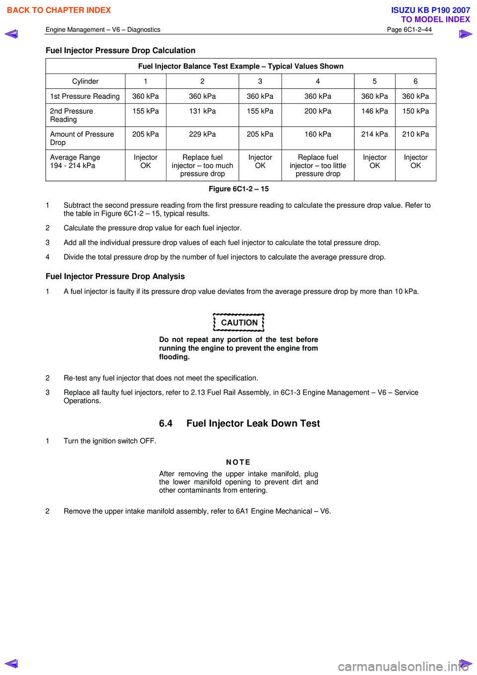
Fuel Injector Pressure Drop Calculation
Fuel Injector Balance Test Example – Typical Values Shown
Cylinder 1 2 3 4 5 6
1st Pressure Reading 360 kPa 360 kPa 360 kPa 360 kPa 360 kPa 360 kPa
2nd Pressure
Reading 155 kPa 131 kPa 155 kPa 200 kPa 146 kPa 150 kPa
Amount of Pressure
Drop 205 kPa 229 kPa 205 kPa 160 kPa 214 kPa 210 kPa
Average Range
194 - 214 kPa Injector
OK Replace fuel
injector – too much pressure drop Injector
OK Replace fuel
injector – too little pressure drop Injector
OK Injector
OK
Figure 6C1-2 – 15
1 Subtract the second pressure reading from the first pressure reading to calculate the pressure drop value. Refer to the table in Figure 6C1-2 – 15, typical results.
2 Calculate the pressure drop value for each fuel injector.
3 Add all the individual pressure drop values of each fuel injector to calculate the total pressure drop.
4 Divide the total pressure drop by the number of fuel injectors to calculate the average pressure drop.
Fuel Injector Pressure Drop Analysis
1 A fuel injector is faulty if its pressure drop value deviates from the average pressure drop by more than 10 kPa.
Do not repeat any portion of the test before
running the engine to prevent the engine from
flooding.
2 Re-test any fuel injector that does not meet the specification.
3 Replace all faulty fuel injectors, refer to 2.13 Fuel Rail Assembly, in 6C1-3 Engine Management – V6 – Service Operations.
6.4 Fuel Injector Leak Down Test
1 Turn the ignition switch OFF.
NOTE
After removing the upper intake manifold, plug
the lower manifold opening to prevent dirt and
other contaminants from entering.
2 Remove the upper intake manifold assembly, refer to 6A1 Engine Mechanical – V6.
BACK TO CHAPTER INDEX
TO MODEL INDEX
ISUZU KB P190 2007