2007 ISUZU KB P190 ignition
[x] Cancel search: ignitionPage 3256 of 6020
Engine Management – V6 – General Information Page 6C1-1–14
Throttle Body Relearn Procedure
The ECM stores values that include the lowest possible TP sensor positions (zero percent), the rest positions (seven
percent), and the spring return rate. These values will only be erased or overwritten if the ECM is reprogrammed or if a
throttle body relearn procedure is performed.
NOTE
If the battery has been disconnected, the ECM
performs a throttle body relearn procedure once
the battery has been reconnected and the ignition
turned on.
The ECM performs a throttle body relearn procedure anytime the ignition is turned on and the following conditions have
been met:
• The engine has been off for greater than 29 seconds,
• The engine speed is less than 40 rpm,
• The vehicle speed is 0 km/h,
• The engine coolant temperature (ECT) is 5 – 60°C; if Tech 2 is used to perform the relearn procedure, the ECT is
5 – 100°C,
• The intake air temperature (IAT) is greater than 5 – 60°C; if Tech 2 is used to perform the relearn procedure, the
IAT is 5 – 100°C,
• The APP sensor angle is less than 15 percent, and
• Ignition voltage is greater than 10 V.
The throttle body relearn procedure is performed 29 seconds after the ignition is turned on. The ECM commands the
throttle plate from the rest position (seven percent open) to full closed (zero percent), then to around 10 percent open.
This procedure takes about six – eight seconds. If any faults occur in the TAC system, a DTC sets. At the start of this
procedure, the Tech 2 TAC Learn Counter parameter should display 0, then count up to 11 after the procedure is
completed. If the counter did not start at 0, or if the counter did not end at 11, a fault has occurred and a DTC should set.
TAC System Default Actions / Reduce Power Modes
The ECM switches to the following reduce power modes if the ECM detects a fault condition in the TAC system:
• If an APP sensor circuit fault or TP sensor circuit fault is detected, the ECM limits engine torque so the vehicle
cannot reach speeds of greater than 100 km/h. The ECM remains in this reduce power mode during the entire
ignition cycle, even if the fault is corrected.
• If there is a fault condition with the throttle actuator control circuits, a throttle actuator command vs. actual position
fault, a return spring check fault, or a TP sensor one circuit fault, the ECM limits engine speed to 2500 rpm and
three – six fuel injectors are randomly disabled. At this time the reduce power indicator is commanded on. The
ECM remains in the reduce power mode during the entire ignition cycle even if the fault is corrected.
NOTE
If a TP sensor one or throttle actuator control
circuit fault is present at the time the vehicle is at
idle, with no accelerator pedal angle, the engine
may stall.
Forced Engine Shutdown
A further safety feature which is built into the TAC system is the ECM will initiate an engine shut down if, the ECM’s
internal monitoring functions detects a serious internal fault, the fuel injectors will be turned off.
3.6 Cruise Control System
The cruise control system integrates with the engine control module (ECM) through the powertrain interface module
(PIM), to control the electronic throttle actuator and maintain the vehicle at the speed set by the driver.
BACK TO CHAPTER INDEX
TO MODEL INDEX
ISUZU KB P190 2007
Page 3260 of 6020

Engine Management – V6 – General Information Page 6C1-1–18
3.12 Immobiliser System
The vehicle incorporates an immobiliser system. After the ignition switch is turned to the ON position, and the powertrain
interface module (PIM) has authenticated the immobiliser control unit (ICU), the PIM sends an encrypted security code to
the engine control module (ECM). The ECM compares the received security code with its own security code, and if it is
valid, the ECM enables the vehicle to be started. For further information and diagnosis of the immobiliser system, refer to
11A Immobiliser.
For further information on the PIM, refer to 6E1 Powertrain Interface Module – V6.
BACK TO CHAPTER INDEX
TO MODEL INDEX
ISUZU KB P190 2007
Page 3264 of 6020
Engine Management – V6 – General Information Page 6C1-1–22
4.6 Clutch Pedal Switch Assembly – Manual
Vehicles Only
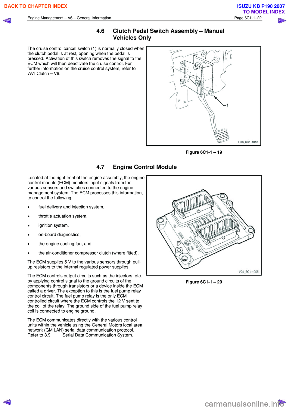
The cruise control cancel switch (1) is normally closed when
the clutch pedal is at rest, opening when the pedal is
pressed. Activation of this switch removes the signal to the
ECM which will then deactivate the cruise control. For
further information on the cruise control system, refer to
7A1 Clutch – V6.
Figure 6C1-1 – 19
4.7 Engine Control Module
Located at the right front of the engine assembly, the engine
control module (ECM) monitors input signals from the
various sensors and switches connected to the engine
management system. The ECM processes this information,
to control the following:
• fuel delivery and injection system,
• throttle actuation system,
• ignition system,
• on-board diagnostics,
• the engine cooling fan, and
• the air-conditioner compressor clutch (where fitted).
The ECM supplies 5 V to the various sensors through pull-
up resistors to the internal regulated power supplies.
The ECM controls output circuits such as the injectors, etc.
by applying control signal to the ground circuits of the
components through transistors or a device inside the ECM
called a driver. The exception to this is the fuel pump relay
control circuit. The fuel pump relay is the only ECM
controlled circuit where the ECM controls the 12 V sent to
the coil of the relay. The ground side of the fuel pump relay
coil is connected to engine ground.
The ECM communicates directly with the various control
units within the vehicle using the General Motors local area
network (GM LAN) serial data communication protocol.
Refer to 3.9 Serial Data Communication System.
Figure 6C1-1 – 20
BACK TO CHAPTER INDEX
TO MODEL INDEX
ISUZU KB P190 2007
Page 3269 of 6020
Engine Management – V6 – General Information Page 6C1-1–27
4.13 Fuel Rail Assembly
The fuel rail assembly is mounted on the lower intake
manifold and distributes the fuel to each cylinder through
individual fuel injectors. The fuel rail assembly consists of:
• the pipe that carries fuel to each injector,
• a fuel pressure test port,
• six individual fuel injectors,
• wiring harness, and
• wiring harness tray.
Figure 6C1-1 – 31
4.14 Heated Oxygen Sensors
The heated oxygen sensors (HO2S) are mounted in the exhaust system and enable the ECM to measure oxygen
content in the exhaust stream. The ECM uses this information to accurately control the air / fuel ratio, because the
oxygen content in the exhaust gas is indicative of the air / fuel ratio of engine combustion.
W hen the sensor is cold, it produces little or no signal voltage, therefore the ECM only reads the HO2S signal when the
HO2S sensor is warm. As soon as the HO2S are warm and outputting a usable signal, the ECM begins making fuel
mixture adjustments based on the HO2S signals. This is known as closed loop mode.
The HFV6 engine has four HO2S, one LSU 4.2 wide-band planar type HO2S upstream of the catalytic converter in each
exhaust pipe, and one LSF 4.2 two-step planar type HO2S in each exhaust pipe downstream of the catalytic converter.
LSF 4.2 Two-step Planar Heated Oxygen Sensors
The LSF 4.2 two-step planar heated oxygen sensors have
four wires:
• The internal heater element supply, which has 12 V
continually applied whenever the ignition is on.
• Heater element ground – The ECM applies pulse
width modulated (PW M) ground to the HO2S heater
control circuit to control the rate at which the sensor
heats up. This reduces the risk of the sensor being
damaged from heating up too quickly under certain
conditions such as extreme cold temperatures. Once
the sensor has reached the desired operating
temperature, the ECM will monitor and continue to
maintain the sensor temperature.
• Sensor signal to the ECM.
• Sensor ground.
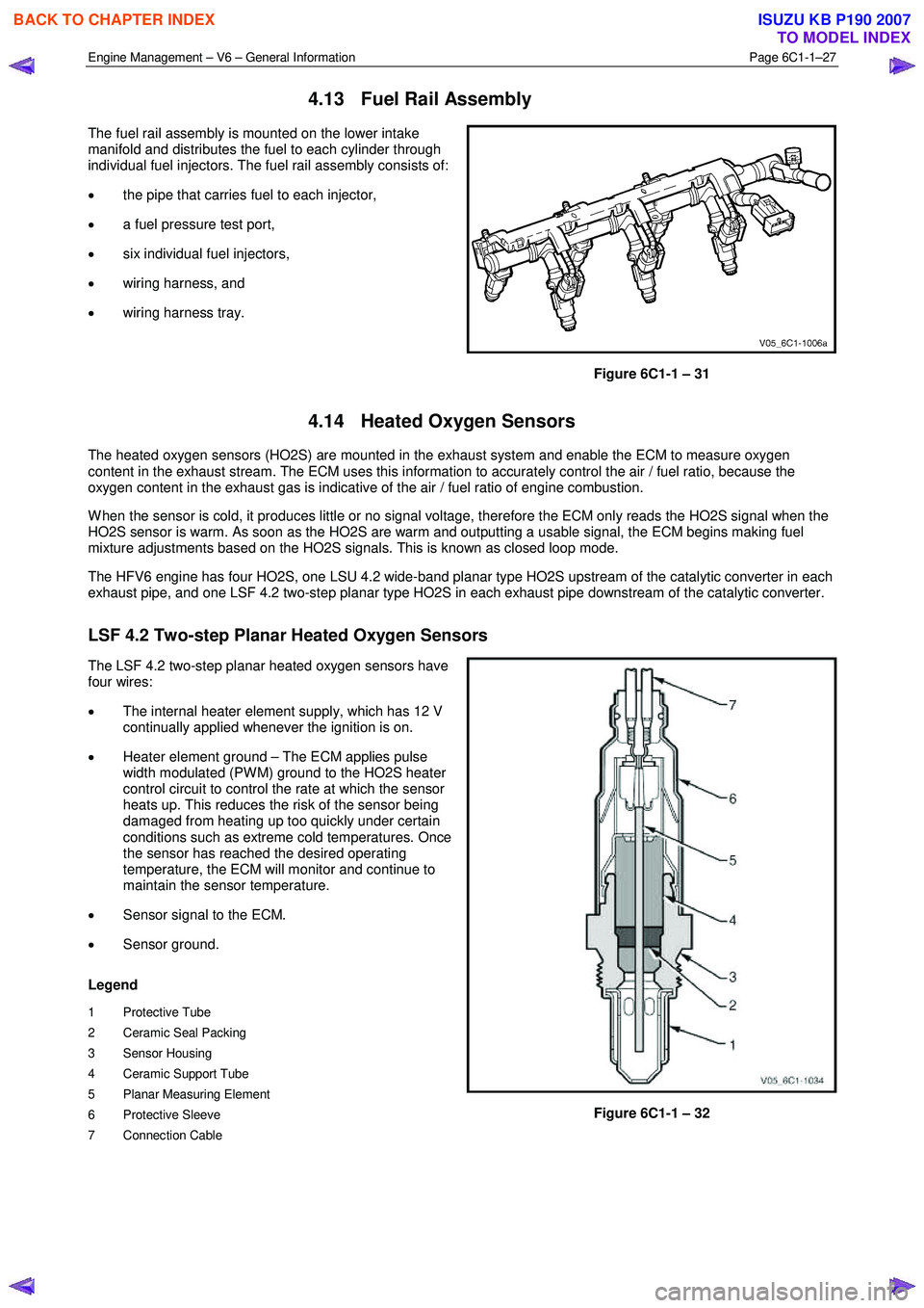
Legend
1 Protective Tube
2 Ceramic Seal Packing
3 Sensor Housing
4 Ceramic Support Tube
5 Planar Measuring Element
6 Protective Sleeve
7 Connection Cable
Figure 6C1-1 – 32
BACK TO CHAPTER INDEX
TO MODEL INDEX
ISUZU KB P190 2007
Page 3271 of 6020
Engine Management – V6 – General Information Page 6C1-1–29
LSU 4.2 Wide-band Planar Heated Oxygen Sensors
The LSU 4.2 wide-band planar heated oxygen sensors have
six wires:
• The internal heater element supply, which has 12 V
continually applied whenever the ignition is on.
• Heater element ground – The ECM applies pulse
width modulated (PW M) ground to the HO2S heater
control circuit to control the rate at which the sensor
heats up. This reduces the risk of the sensor being
damaged from heating up too quickly under certain
conditions such as extreme cold temperatures. Once
the sensor has reached the desired operating
temperature, the ECM will monitor and continue to
maintain the sensor temperature.
• Output voltage.
• Sensor ground.
• Trim current.
• Pumping current.
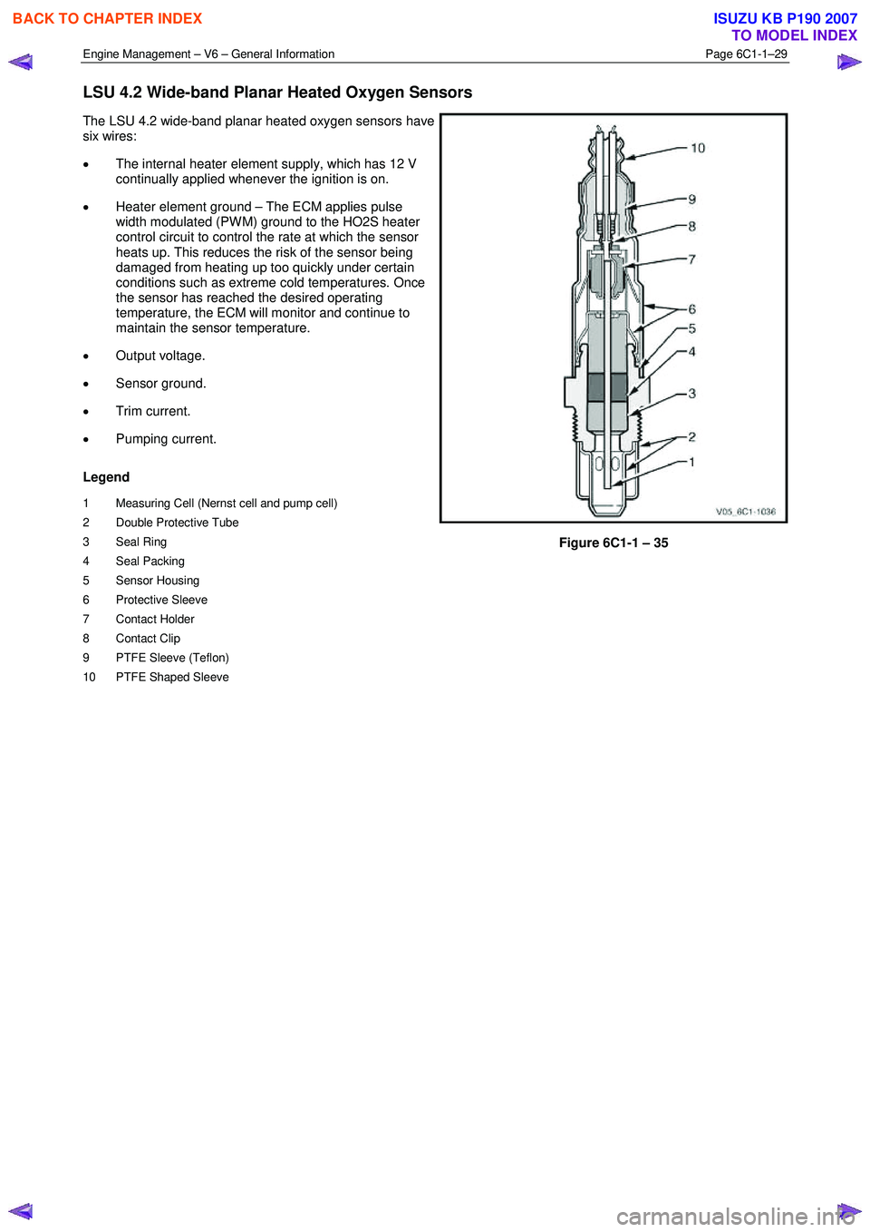
Legend
1 Measuring Cell (Nernst cell and pump cell)
2 Double Protective Tube
3 Seal Ring
4 Seal Packing
5 Sensor Housing
6 Protective Sleeve
7 Contact Holder
8 Contact Clip
9 PTFE Sleeve (Teflon)
10 PTFE Shaped Sleeve
Figure 6C1-1 – 35
BACK TO CHAPTER INDEX
TO MODEL INDEX
ISUZU KB P190 2007
Page 3273 of 6020
Engine Management – V6 – General Information Page 6C1-1–31
4.15 Ignition Coil and Spark Plug
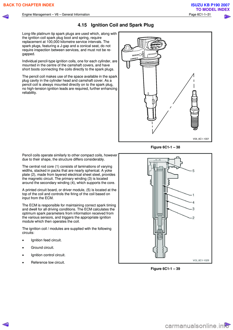
Long-life platinum tip spark plugs are used which, along with
the ignition coil spark plug boot and spring, require
replacement at 100,000 kilometre service intervals. The
spark plugs, featuring a J-gap and a conical seat, do not
require inspection between services, and must not be re-
gapped.
Individual pencil-type ignition coils, one for each cylinder, are
mounted in the centre of the camshaft covers, and have
short boots connecting the coils directly to the spark plugs.
The pencil coil makes use of the space available in the spark
plug cavity in the cylinder head and camshaft cover. As a
pencil coil is always mounted directly on to the spark plug,
no high-tension ignition leads are required, further enhancing
reliability.
Figure 6C1-1 – 38
Pencil coils operate similarly to other compact coils, however
due to their shape, the structure differs considerably.
The central rod core (1) consists of laminations of varying
widths, stacked in packs that are nearly spherical. A yoke
plate (2), made from layered electrical sheet steel, provides
the magnetic circuit. The primary winding (3) is located
around the secondary winding (4), which supports the core.
A printed circuit board, or driver module, (5) is located at the
top of the coil and controls the firing of the coil based on
input from the ECM.
The ECM is responsible for maintaining correct spark timing
and dwell for all driving conditions. The ECM calculates the
optimum spark parameters from information received from
the various sensors, and triggers the appropriate ignition
module which then operates the coil.
The ignition coil / modules are supplied with the following
circuits:
• Ignition feed circuit.
• Ground circuit.
• Ignition control circuit.
• Reference low circuit.
Figure 6C1-1 – 39
BACK TO CHAPTER INDEX
TO MODEL INDEX
ISUZU KB P190 2007
Page 3274 of 6020
Engine Management – V6 – General Information Page 6C1-1–32
4.16 Intake Air Temperature Sensor
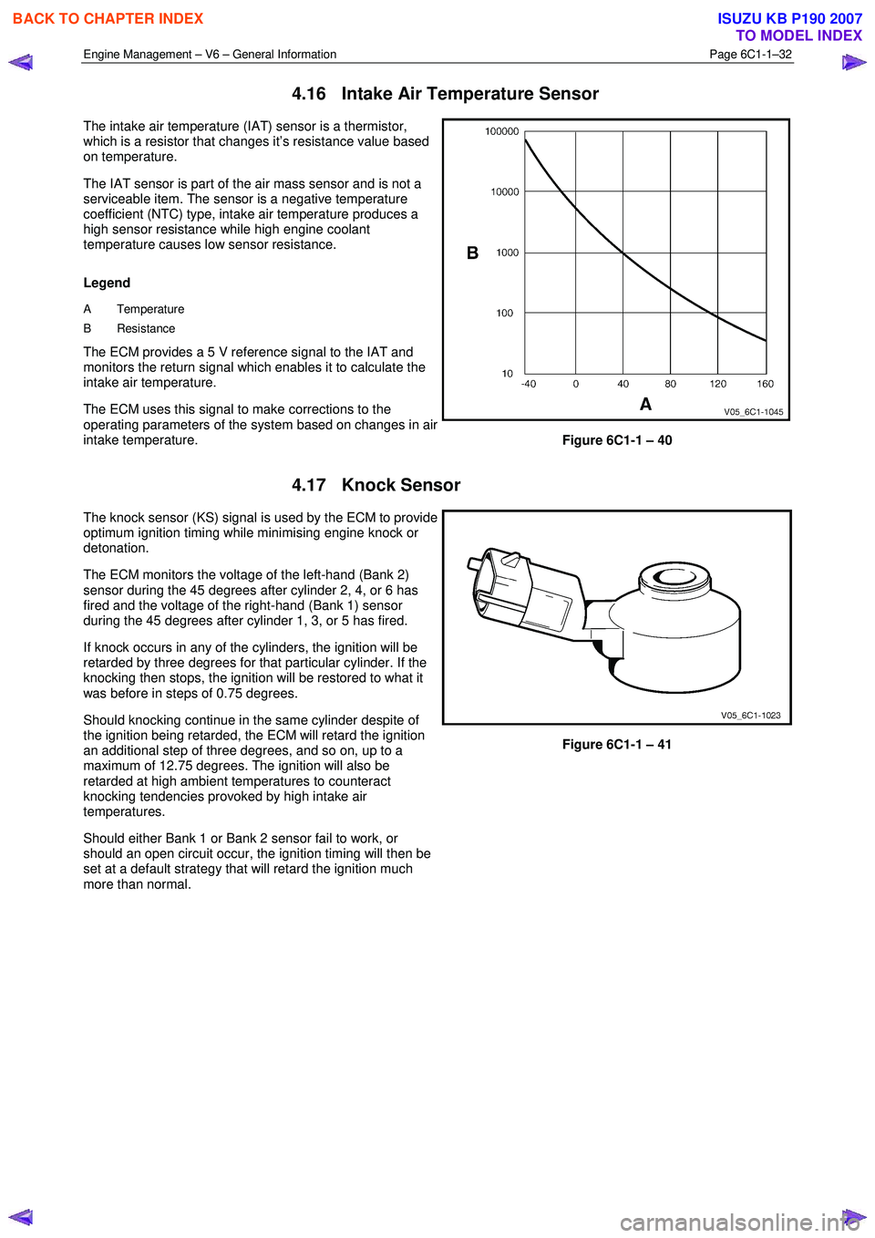
The intake air temperature (IAT) sensor is a thermistor,
which is a resistor that changes it’s resistance value based
on temperature.
The IAT sensor is part of the air mass sensor and is not a
serviceable item. The sensor is a negative temperature
coefficient (NTC) type, intake air temperature produces a
high sensor resistance while high engine coolant
temperature causes low sensor resistance.
Legend
A Temperature
B Resistance
The ECM provides a 5 V reference signal to the IAT and
monitors the return signal which enables it to calculate the
intake air temperature.
The ECM uses this signal to make corrections to the
operating parameters of the system based on changes in air
intake temperature.
Figure 6C1-1 – 40
4.17 Knock Sensor
The knock sensor (KS) signal is used by the ECM to provide
optimum ignition timing while minimising engine knock or
detonation.
The ECM monitors the voltage of the left-hand (Bank 2)
sensor during the 45 degrees after cylinder 2, 4, or 6 has
fired and the voltage of the right-hand (Bank 1) sensor
during the 45 degrees after cylinder 1, 3, or 5 has fired.
If knock occurs in any of the cylinders, the ignition will be
retarded by three degrees for that particular cylinder. If the
knocking then stops, the ignition will be restored to what it
was before in steps of 0.75 degrees.
Should knocking continue in the same cylinder despite of
the ignition being retarded, the ECM will retard the ignition
an additional step of three degrees, and so on, up to a
maximum of 12.75 degrees. The ignition will also be
retarded at high ambient temperatures to counteract
knocking tendencies provoked by high intake air
temperatures.
Should either Bank 1 or Bank 2 sensor fail to work, or
should an open circuit occur, the ignition timing will then be
set at a default strategy that will retard the ignition much
more than normal.
Figure 6C1-1 – 41
BACK TO CHAPTER INDEX
TO MODEL INDEX
ISUZU KB P190 2007
Page 3277 of 6020
Engine Management – V6 – General Information Page 6C1-1–35
5 Abbreviations and Glossary of
Te r m s
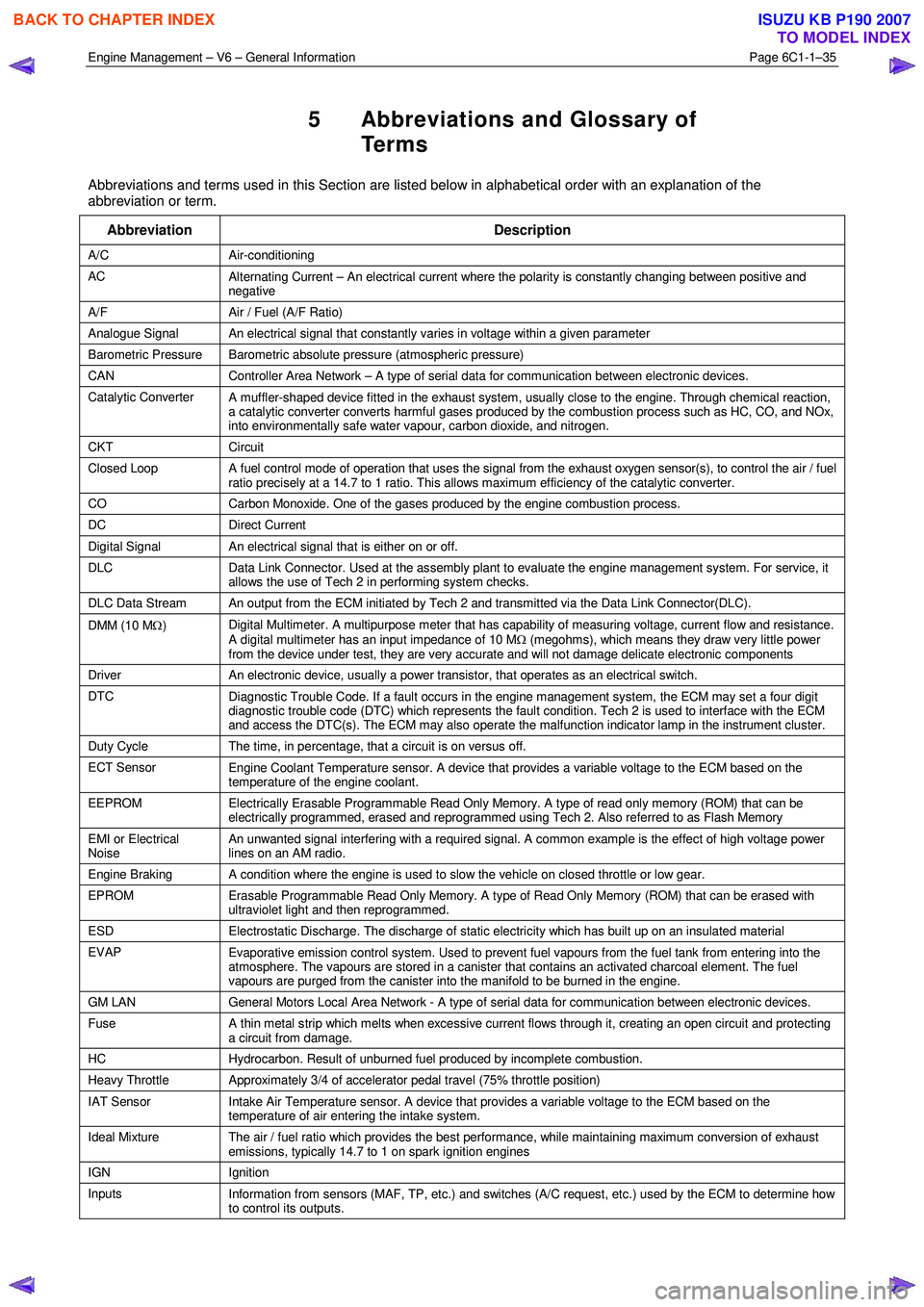
Abbreviations and terms used in this Section are listed below in alphabetical order with an explanation of the
abbreviation or term.
Abbreviation Description
A/C Air-conditioning
AC Alternating Current – An electrical current where the polarity is constantly changing between positive and
negative
A/F Air / Fuel (A/F Ratio)
Analogue Signal An electrical signal that constantly varies in voltage within a given parameter
Barometric Pressure Barometric absolute pressure (atmospheric pressure)
CAN Controller Area Network – A type of serial data for communication between electronic devices.
Catalytic Converter
A muffler-shaped device fitted in the exhaust system, usually close to the engine. Through chemical reaction,
a catalytic converter converts harmful gases produced by the combustion process such as HC, CO, and NOx,
into environmentally safe water vapour, carbon dioxide, and nitrogen.
CKT Circuit
Closed Loop A fuel control mode of operation that uses the signal from the exhaust oxygen sensor(s), to control the air / fuel
ratio precisely at a 14.7 to 1 ratio. This allows maximum efficiency of the catalytic converter.
CO Carbon Monoxide. One of the gases produced by the engine combustion process.
DC Direct Current
Digital Signal An electrical signal that is either on or off.
DLC
Data Link Connector. Used at the assembly plant to evaluate the engine management system. For service, it
allows the use of Tech 2 in performing system checks.
DLC Data Stream An output from the ECM initiated by Tech 2 and transmitted via the Data Link Connector(DLC).
DMM (10 M Ω) Digital Multimeter. A multipurpose meter that has capability of measuring voltage, current flow and resistance.
A digital multimeter has an input impedance of 10 M Ω (megohms), which means they draw very little power
from the device under test, they are very accurate and will not damage delicate electronic components
Driver An electronic device, usually a power transistor, that operates as an electrical switch.
DTC
Diagnostic Trouble Code. If a fault occurs in the engine management system, the ECM may set a four digit
diagnostic trouble code (DTC) which represents the fault condition. Tech 2 is used to interface with the ECM
and access the DTC(s). The ECM may also operate the malfunction indicator lamp in the instrument cluster.
Duty Cycle The time, in percentage, that a circuit is on versus off.
ECT Sensor
Engine Coolant Temperature sensor. A device that provides a variable voltage to the ECM based on the
temperature of the engine coolant.
EEPROM Electrically Erasable Programmable Read Only Memory. A type of read only memory (ROM) that can be
electrically programmed, erased and reprogrammed using Tech 2. Also referred to as Flash Memory
EMI or Electrical
Noise An unwanted signal interfering with a required signal. A common example is the effect of high voltage power
lines on an AM radio.
Engine Braking A condition where the engine is used to slow the vehicle on closed throttle or low gear.
EPROM Erasable Programmable Read Only Memory. A type of Read Only Memory (ROM) that can be erased with
ultraviolet light and then reprogrammed.
ESD Electrostatic Discharge. The discharge of static electricity which has built up on an insulated material
EVAP
Evaporative emission control system. Used to prevent fuel vapours from the fuel tank from entering into the
atmosphere. The vapours are stored in a canister that contains an activated charcoal element. The fuel
vapours are purged from the canister into the manifold to be burned in the engine.
GM LAN General Motors Local Area Network - A type of serial data for communication between electronic devices.
Fuse
A thin metal strip which melts when excessive current flows through it, creating an open circuit and protecting
a circuit from damage.
HC Hydrocarbon. Result of unburned fuel produced by incomplete combustion.
Heavy Throttle Approximately 3/4 of accelerator pedal travel (75% throttle position)
IAT Sensor
Intake Air Temperature sensor. A device that provides a variable voltage to the ECM based on the
temperature of air entering the intake system.
Ideal Mixture The air / fuel ratio which provides the best performance, while maintaining maximum conversion of exhaust
emissions, typically 14.7 to 1 on spark ignition engines
IGN Ignition
Inputs Information from sensors (MAF, TP, etc.) and switches (A/C request, etc.) used by the ECM to determine how
to control its outputs.
BACK TO CHAPTER INDEX
TO MODEL INDEX
ISUZU KB P190 2007