2007 ISUZU KB P190 speaker
[x] Cancel search: speakerPage 3297 of 6020
Engine Management – V6 – Diagnostics Page 6C1-2–19
• Do not start the engine if the battery terminal is not properly secured to the battery.
• Do not disconnect or reconnect the following while the ignition is switched on or when the engine is running:
− Any engine management system component electrical wiring connector, or
− Battery terminal leads.
• Ensure the correct procedure for disconnecting and connecting engine management system electrical wiring
connectors is always followed. For information on the correct procedure for disconnecting and connecting specific
wiring connectors, refer to 6C1-3 Engine Management – V6 – Service Operations.
• Ensure that all wiring harness connectors are fitted correctly.
• W hen steam or pressure cleaning engines, do not direct the cleaning nozzle at engine management system
components.
• Do not clear any DTCs unless instructed.
• The fault must be present when using the diagnostic trouble code (DTC) diagnostic tables. Otherwise,
misdiagnosis or replacement of good parts may occur.
• Do not touch the ECM connector pins or soldered components on the ECM circuit board to prevent ECM
Electrostatic Discharge damage. Refer to 8A Electrical - Body and Chassis for information on Electrostatic
Discharge.
• Use only the test equipment specified in the diagnostic tables as other test equipment may give incorrect results or
damage good components.
• The ECM is designed to withstand normal current draw associated with vehicle operations. However, the following
fault conditions or incorrect test procedure may overload the ECM internal circuit and damage the ECM:
− A short to voltage fault condition in any of the ECM low reference circuits may cause internal ECM and / or
sensor damage. Therefore, any short to voltage fault condition in the ECM low reference circuits must be
rectified before replacing a faulty component.
− A short to ground fault condition in any of the ECM 5 V reference circuits may cause internal ECM and / or
sensor damage. Therefore, any short to ground fault condition in the ECM 5 V reference circuits must be
rectified before replacing a faulty component.
− W hen using a test lamp to test an electrical circuit, do not use any of the ECM low reference circuits or 5 V
reference circuits as a reference point. Otherwise, excessive current draw from the test lamp may damage
the ECM.
• Disregard DTCs that set while performing the following diagnostic Steps:
− Using Tech 2 actuator tests, or
− Disconnecting an engine management system sensor connector then switching on the ignition.
• After completing the required diagnostics and service operations, road test the vehicle to ensure correct engine
management system operation.
4.3 Preliminary Checks
The preliminary checks are a set of visual and physical checks or inspections that may quickly identify engine
management system fault condition.
• Refer to the appropriate Service Techlines for relevant information regarding the fault condition.
• Ensure the battery is fully charged.
• Inspect the battery connections for corrosion or a loose terminal.
• Ensure that all engine management system related fuses are serviceable.
• Inspect for incorrect aftermarket theft deterrent devices, lights or mobile phone installation.
• Ensure there is no speaker magnet positioned too close to any electronic module that contains relays.
• Inspect the engine wiring harness for proper connections, pinches or cuts.
• Ensure that all engine management related electrical wiring connectors are fitted correctly.
• Inspect the ECM ground connections for corrosion, loose terminal or incorrect position.
BACK TO CHAPTER INDEX
TO MODEL INDEX
ISUZU KB P190 2007
Page 3814 of 6020
Automatic Transmission – 4L60E – Electrical Diagnosis Page 7C2–28
7 Ensure that all wiring harness connectors are fitted correctly and secure.
8 W hen steam or pressure cleaning vehicle components, such as engines, transmissions, etc., do not direct the cleaning nozzle at any system electrical wiring harness connectors or components.
9 Do not clear any DTCs unless instructed.
10 The fault must be present when using the Diagnostic Trouble Code (DTC) Diagnostic Tables. Otherwise, misdiagnosis or replacement of good parts may occur.
11 Do not touch any electronic control module connector pins or soldered components on the circuit board. This is required to avoid the possibility of electrostatic discharge damage.
12 Use only the test equipment specified in the diagnostic tables, as other test equipment may give incorrect results or damage good components.
13 Electronic control modules are designed to withstand normal current draws associated with vehicle operation. However, the following fault conditions or incorrect test procedure may overload internal control module circuits and
irreparably damage the control module:
• A short to voltage fault condition in any of the control module low reference circuits may cause internal and/or
sensor damage. Therefore, any short to voltage fault condition in the control module low reference circuits
must be rectified before replacing a faulty component.
• A short to ground fault condition in any of the control module 5 volts reference circuits may cause internal
control module and/or sensor damage. Therefore, any short to ground fault condition in the control module 5
volt reference circuits must be rectified before replacing a faulty component.
• W hen using a test light to test an electrical circuit, do not use any of the control module low reference circuits
or 5 volts reference circuits as a reference point. Otherwise, excessive current draw from the test light may
damage the control module.
14 Disregard DTCs that set while performing the following diagnostic Steps:
• Using the Tech 2 output control function, or
• Disconnecting a control module system sensor connector then switching the ignition ON.
15 After completing the required diagnostics and service operations, road test the vehicle to ensure correct system operation.
4.4 Preliminary Checks
The Preliminary Checks is a set of visual and physical checks or inspections that may quickly identify a control module
system fault condition:
1 Refer to relevant Service Techlines for information regarding the fault condition.
2 Ensure that the battery is fully charged.
3 Inspect the battery connections for corrosion or a loose terminal.
4 Ensure that all relevant control module system related fuses are serviceable.
5 Inspect for incorrect aftermarket theft deterrent devices, lights or mobile phone installation.
6 Ensure that there is no speaker magnet positioned too close to any electronic module that contains relays.
7 Inspect the system wiring harness for proper connections, pinches or cuts.
8 Ensure that all control module related electrical wiring connectors are fitted correctly.
9 Inspect the control module ground connections for corrosion, loose terminal or incorrect position.
10 Ensure that the resistance between the control module housing and the battery ground cable is less than 0.5 ohms.
11 Check that the control module and its mounting bracket is secure.
12 Check all control module related components for correct installation.
13 Check the control module and related wiring harness routing to ensure that no rubbing or cutting of the wiring harness by sharp body components can occur.
BACK TO CHAPTER INDEX
TO MODEL INDEX
ISUZU KB P190 2007
Page 5555 of 6020
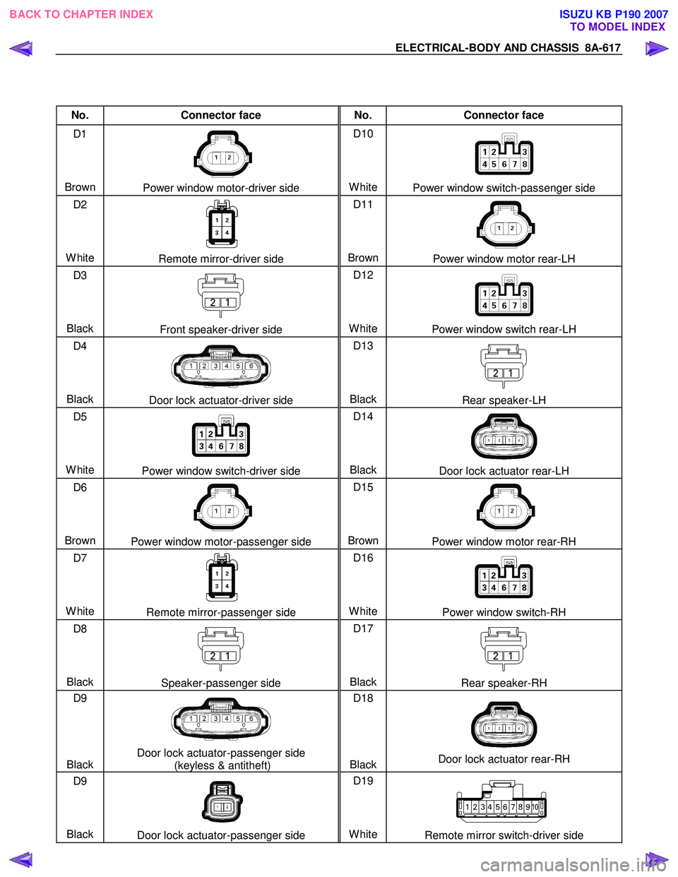
ELECTRICAL-BODY AND CHASSIS 8A-617
No. Connector face No. Connector face
D1
Brown
Power window motor-driver side D10
White
Power window switch-passenger side
D2
White
Remote mirror-driver side D11
BrownPower window motor rear-LH
D3
Black
Front speaker-driver side D12
White
Power window switch rear-LH
D4
Black
Door lock actuator-driver side D13
BlackRear speaker-LH
D5
White
Power window switch-driver side D14
BlackDoor lock actuator rear-LH
D6
Brown
Power window motor-passenger side D15
BrownPower window motor rear-RH
D7
White
Remote mirror-passenger side D16
WhitePower window switch-RH
D8
Black
Speaker-passenger side D17
BlackRear speaker-RH
D9
Black
Door lock actuator-passenger side (keyless & antitheft) D18
BlackDoor lock actuator rear-RH
D9
Black
Door lock actuator-passenger side D19
WhiteRemote mirror switch-driver side
BACK TO CHAPTER INDEX TO MODEL INDEXISUZU KB P190 2007
Page 5569 of 6020
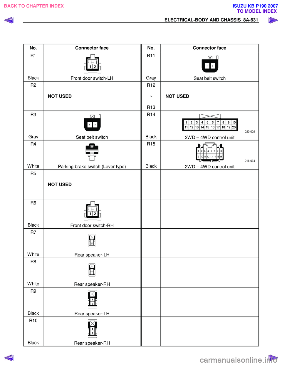
ELECTRICAL-BODY AND CHASSIS 8A-631
No. Connector face No. Connector face
R1
Black
Front door switch-LH R11
Gray Seat belt switch
R2
NOT USED R12
~
R13 NOT USED
R3
Gray
Seat belt switch R14
Black2W D – 4W D control unit
R4
White
Parking brake switch (Lever type) R15
Black2W D – 4W D control unit
R5
NOT USED
R6
Black
Front door switch-RH
R7
White
Rear speaker-LH
R8
White
Rear speaker-RH
R9
Black
Rear speaker-LH
R10
Black
Rear speaker-RH
BACK TO CHAPTER INDEX
TO MODEL INDEXISUZU KB P190 2007
Page 5606 of 6020
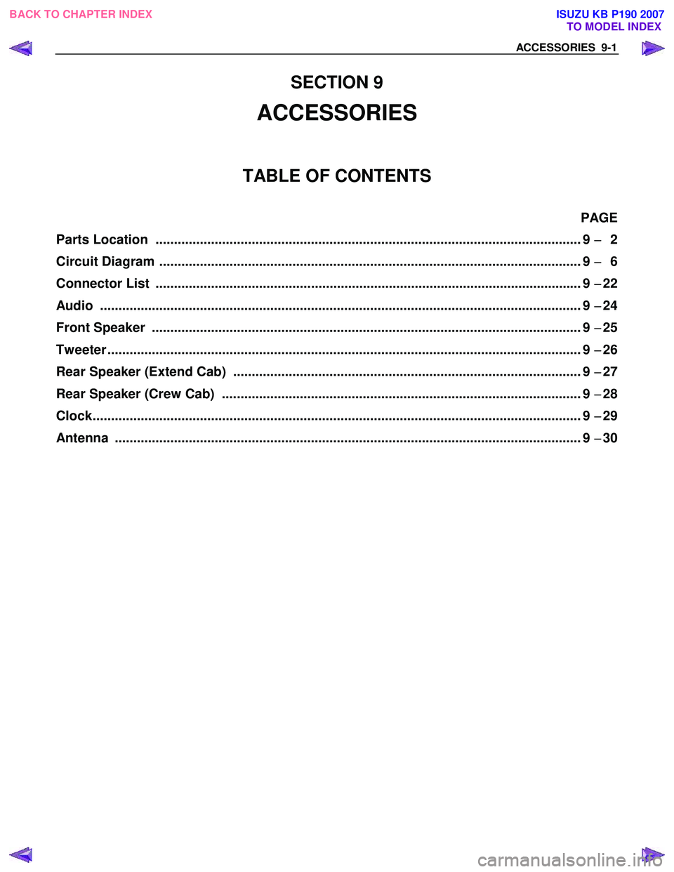
ACCESSORIES 9-1
SECTION 9
ACCESSORIES
TABLE OF CONTENTS
PAGE
Parts Location ................................................................................................................ ... 9 −
−−
−
2
Circuit Diagram ............................................................................................................... ... 9 −
−−
−
6
Connector List ................................................................................................................ ... 9 −
−−
−
22
Audio ......................................................................................................................... ......... 9 −
−−
−
24
Front Speaker ................................................................................................................. ... 9 −
−−
−
25
Tweeter ........................................................................................................................ ........ 9 −
−−
−
26
Rear Speaker (Extend Cab) .............................................................................................. 9 −
−−
−
27
Rear Speaker (Crew Cab) ................................................................................................. 9 −
−−
−
28
Clock.......................................................................................................................... .......... 9 −
−−
−
29
Antenna ....................................................................................................................... ....... 9 −
−−
−
30
BACK TO CHAPTER INDEX
TO MODEL INDEXISUZU KB P190 2007
Page 5627 of 6020
9-22 ACCESSORIES
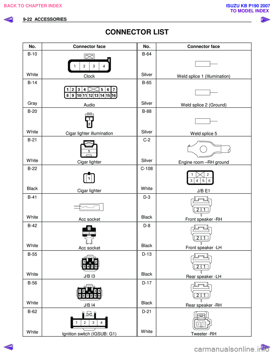
CONNECTOR LIST
No. Connector face No. Connector face
B-10
White
Clock B-64
SilverW eld splice 1 (Illumination)
B-14
Gray
Audio B-65
SilverW eld splice 2 (Ground)
B-20
White
Cigar lighter illumination B-88
SilverW eld splice 5
B-21
White
Cigar lighter C-2
SilverEngine room –RH ground
B-22
Black
Cigar lighter C-108
White
J/B E1
B-41
White
Acc socket D-3
BlackFront speaker -RH
B-42
White
Acc socket D-8
BlackFront speaker -LH
B-55
White
J/B I3 D-13
BlackRear speaker -LH
B-56
White
J/B I4 D-17
BlackRear speaker -RH
B-62
White
Ignition switch (IGSUB: G1) D-21
WhiteTweeter -RH
BACK TO CHAPTER INDEX TO MODEL INDEXISUZU KB P190 2007
Page 5628 of 6020
ACCESSORIES 9-23
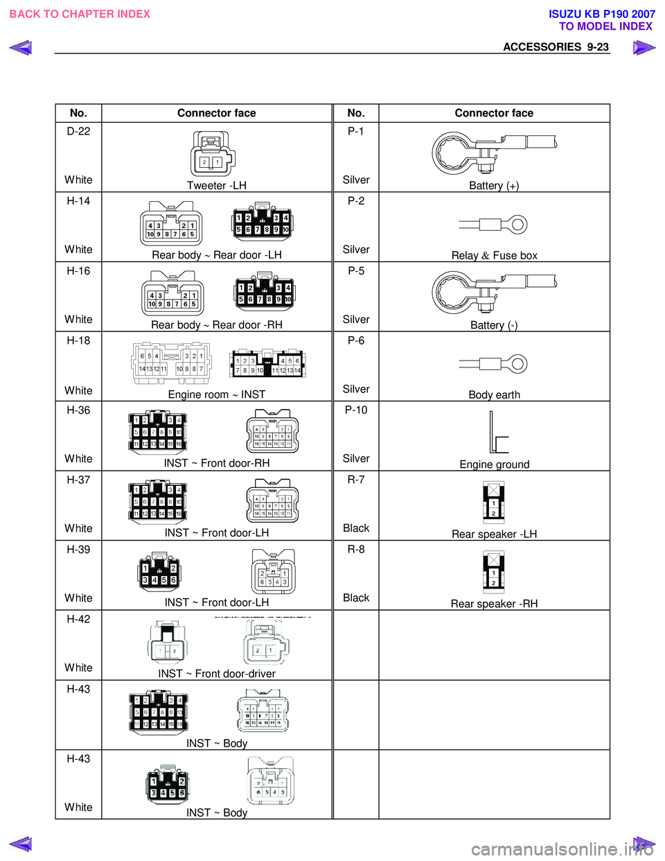
No. Connector face No. Connector face
D-22
White
Tweeter -LH P-1
SilverBattery (+)
H-14
White
Rear body ∼ Rear door -LH P-2
SilverRelay & Fuse box
H-16
White
Rear body ∼ Rear door -RH P-5
SilverBattery (-)
H-18
White
Engine room ∼ INST P-6
SilverBody earth
H-36
White
INST ~ Front door-RH P-10
SilverEngine ground
H-37
White
INST ~ Front door-LH R-7
BlackRear speaker -LH
H-39
White
INST ~ Front door-LH R-8
BlackRear speaker -RH
H-42
White
INST ~ Front door-driver
H-43
INST ~ Body
H-43
White
INST ~ Body
BACK TO CHAPTER INDEX TO MODEL INDEXISUZU KB P190 2007
Page 5630 of 6020
ACCESSORIES 9-25
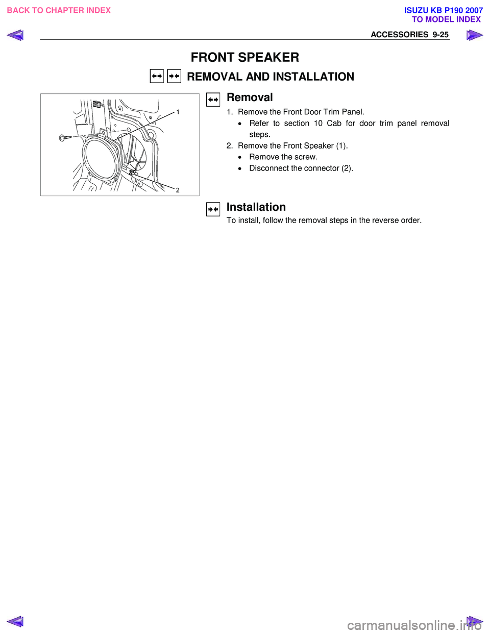
FRONT SPEAKER
REMOVAL AND INSTALLATION
Removal
1. Remove the Front Door Trim Panel.
• Refer to section 10 Cab for door trim panel removal
steps.
2. Remove the Front Speaker (1). • Remove the screw.
• Disconnect the connector (2).
Installation
To install, follow the removal steps in the reverse order.
BACK TO CHAPTER INDEX TO MODEL INDEXISUZU KB P190 2007