2007 INFINITI QX56 Cam shaft position sensor
[x] Cancel search: Cam shaft position sensorPage 1091 of 3061

EC-8
DTC Confirmation Procedure ................................567
Wiring Diagram ......................................................569
Diagnosis Procedure .............................................570
Component Inspection ...........................................572
Removal and Installation .......................................573
DTC P2135 TP SENSOR .................................574
Component Description .........................................574
CONSULT-II Reference Value in Data Monitor
Mode ......................................................................
574
On Board Diagnosis Logic .....................................574
DTC Confirmation Procedure ................................574
Wiring Diagram ......................................................576
Diagnosis Procedure .............................................577
Component Inspection ...........................................579
Removal and Installation .......................................580
DTC P2138 APP SENSOR ..............................581
Component Description .........................................581
CONSULT-II Reference Value in Data Monitor
Mode ......................................................................
581
On Board Diagnosis Logic .....................................581
DTC Confirmation Procedure ................................582
Wiring Diagram ......................................................583
Diagnosis Procedure .............................................584
Component Inspection ...........................................587
Removal and Installation .......................................587
DTC P2A00, P2A03 A/F SENSOR 1 ...............588
Component Description .........................................588
CONSULT-II Reference Value in Data Monitor
Mode ......................................................................
588
On Board Diagnosis Logic .....................................588
DTC Confirmation Procedure ................................588
Wiring Diagram ......................................................590
Diagnosis Procedure .............................................593
Removal and Installation .......................................596
ASCD BRAKE SWITCH ..................................597
Component Description .........................................597
CONSULT-II Reference Value in Data Monitor
Mode ......................................................................
597
Wiring Diagram ......................................................598
Diagnosis Procedure .............................................599
Component Inspection ...........................................602
ASCD INDICATOR ..........................................603
Component Description .........................................603
CONSULT-II Reference Value in Data Monitor
Mode ......................................................................
603
Wiring Diagram ......................................................604
Diagnosis Procedure .............................................604
ELECTRICAL LOAD SIGNAL .........................606
Description .............................................................606
CONSULT-II Reference Value in Data Monitor
Mode ......................................................................
606
Diagnosis Procedure .............................................606
FUEL INJECTOR ..............................................608
Component Description ........................................608
CONSULT-II Reference Value in Data Monitor
Mode .....................................................................
608
Wiring Diagram .....................................................609
Diagnosis Procedure .............................................610
Component Inspection ..........................................612
Removal and Installation .......................................612
FUEL PUMP .....................................................613
Description ............................................................613
CONSULT-II Reference Value in Data Monitor
Mode .....................................................................
613
Wiring Diagram .....................................................614
Diagnosis Procedure .............................................615
Component Inspection ..........................................617
Removal and Installation .......................................618
ICC BRAKE SWITCH .......................................619
Component Description ........................................619
CONSULT-II Reference Value in Data Monitor
Mode .....................................................................
619
Wiring Diagram .....................................................620
Diagnosis Procedure .............................................621
Component Inspection ..........................................624
IGNITION SIGNAL ............................................626
Component Description ........................................626
Wiring Diagram .....................................................627
Diagnosis Procedure .............................................632
Component Inspection ..........................................635
Removal and Installation .......................................637
REFRIGERANT PRESSURE SENSOR ...........638
Component Description ........................................638
Wiring Diagram .....................................................639
Diagnosis Procedure .............................................640
Removal and Installation .......................................642
MIL AND DATA LINK CONNECTOR ...............643
Wiring Diagram .....................................................643
SERVICE DATA AND SPECIFICATIONS
(SDS) ................................................................
645
Fuel Pressure ........................................................645
Idle Speed and Ignition Timing .............................645
Calculated Load Value ..........................................645
Mass Air Flow Sensor ...........................................645
Intake Air Temperature Sensor .............................645
Engine Coolant Temperature Sensor ...................645
A/F Sensor 1 Heater .............................................645
Heated Oxygen sensor 2 Heater ..........................645
Crankshaft Position Sensor (POS) .......................646
Camshaft Position Sensor (PHASE) .....................646
Throttle Control Motor ...........................................646
Fuel Injector ..........................................................646
Fuel Pump .............................................................646
Page 1101 of 3061
EC-18
< SERVICE INFORMATION >
PRECAUTIONS
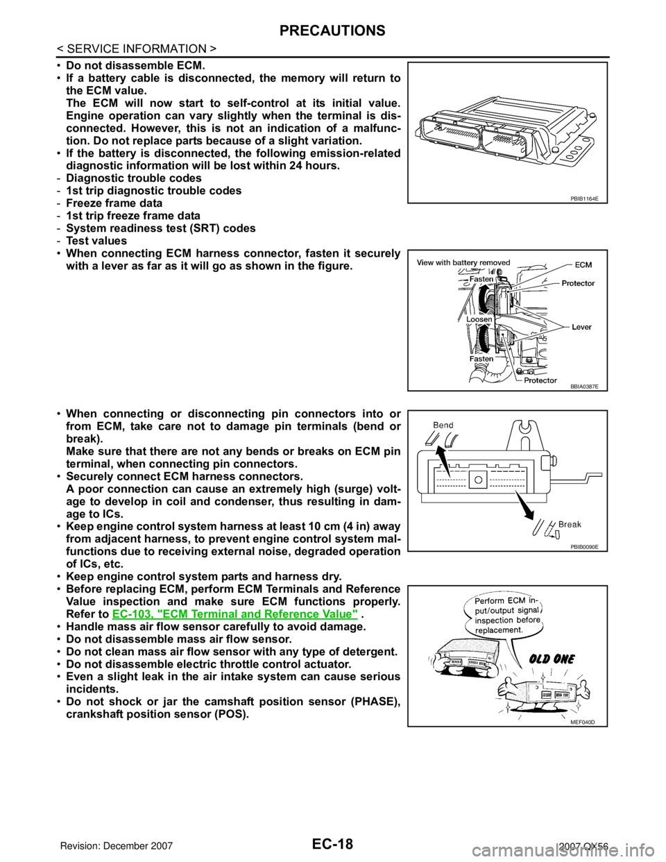
•Do not disassemble ECM.
•If a battery cable is disconnected, the memory will return to
the ECM value.
The ECM will now start to self-control at its initial value.
Engine operation can vary slightly when the terminal is dis-
connected. However, this is not an indication of a malfunc-
tion. Do not replace parts because of a slight variation.
•If the battery is disconnected, the following emission-related
diagnostic information will be lost within 24 hours.
-Diagnostic trouble codes
-1st trip diagnostic trouble codes
-Freeze frame data
-1st trip freeze frame data
-System readiness test (SRT) codes
-Test values
•When connecting ECM harness connector, fasten it securely
with a lever as far as it will go as shown in the figure.
•When connecting or disconnecting pin connectors into or
from ECM, take care not to damage pin terminals (bend or
break).
Make sure that there are not any bends or breaks on ECM pin
terminal, when connecting pin connectors.
•Securely connect ECM harness connectors.
A poor connection can cause an extremely high (surge) volt-
age to develop in coil and condenser, thus resulting in dam-
age to ICs.
•Keep engine control system harness at least 10 cm (4 in) away
from adjacent harness, to prevent engine control system mal-
functions due to receiving external noise, degraded operation
of ICs, etc.
•Keep engine control system parts and harness dry.
•Before replacing ECM, perform ECM Terminals and Reference
Value inspection and make sure ECM functions properly.
Refer to EC-103, "
ECM Terminal and Reference Value" .
•Handle mass air flow sensor carefully to avoid damage.
•Do not disassemble mass air flow sensor.
•Do not clean mass air flow sensor with any type of detergent.
•Do not disassemble electric throttle control actuator.
•Even a slight leak in the air intake system can cause serious
incidents.
•Do not shock or jar the camshaft position sensor (PHASE),
crankshaft position sensor (POS).
PBIB1164E
BBIA0387E
PBIB0090E
MEF040D
Page 1108 of 3061
ENGINE CONTROL SYSTEM
EC-25
< SERVICE INFORMATION >
C
D
E
F
G
H
I
J
K
L
MA
EC
N
P O
*1: This sensor is not used to control the engine system. This is used only for the on board diagnosis.
*2: This signal is sent to the ECM through CAN communication line.
*3: ECM determines the start signal status by the signals of engine speed and battery voltage.
SYSTEM DESCRIPTION
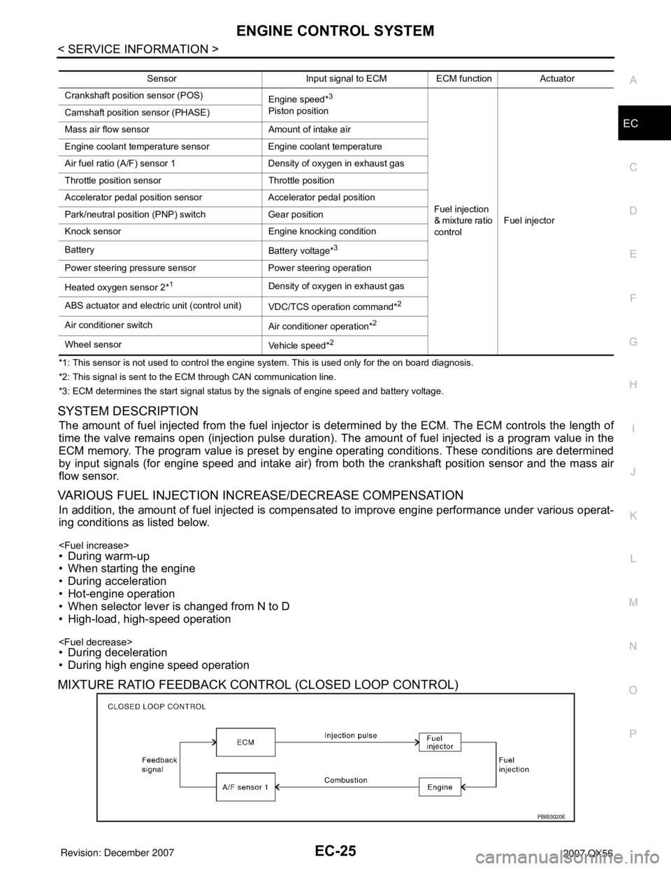
The amount of fuel injected from the fuel injector is determined by the ECM. The ECM controls the length of
time the valve remains open (injection pulse duration). The amount of fuel injected is a program value in the
ECM memory. The program value is preset by engine operating conditions. These conditions are determined
by input signals (for engine speed and intake air) from both the crankshaft position sensor and the mass air
flow sensor.
VARIOUS FUEL INJECTION INCREASE/DECREASE COMPENSATION
In addition, the amount of fuel injected is compensated to improve engine performance under various operat-
ing conditions as listed below.
• When starting the engine
• During acceleration
• Hot-engine operation
• When selector lever is changed from N to D
• High-load, high-speed operation
• During deceleration
• During high engine speed operation
MIXTURE RATIO FEEDBACK CONTROL (CLOSED LOOP CONTROL)
Sensor Input signal to ECM ECM function Actuator
Crankshaft position sensor (POS)
Engine speed*
3
Piston position
Fuel injection
& mixture ratio
controlFuel injector Camshaft position sensor (PHASE)
Mass air flow sensor Amount of intake air
Engine coolant temperature sensor Engine coolant temperature
Air fuel ratio (A/F) sensor 1 Density of oxygen in exhaust gas
Throttle position sensor Throttle position
Accelerator pedal position sensor Accelerator pedal position
Park/neutral position (PNP) switch Gear position
Knock sensor Engine knocking condition
Battery
Battery voltage*
3
Power steering pressure sensor Power steering operation
Heated oxygen sensor 2*
1Density of oxygen in exhaust gas
ABS actuator and electric unit (control unit)
VDC/TCS operation command*
2
Air conditioner switch
Air conditioner operation*2
Wheel sensor
Vehicle speed*2
PBIB3020E
Page 1110 of 3061

ENGINE CONTROL SYSTEM
EC-27
< SERVICE INFORMATION >
C
D
E
F
G
H
I
J
K
L
MA
EC
N
P O
This system is used when the engine is being started and/or if the fail-safe system (CPU) is operating.
FUEL SHUT-OFF
Fuel to each cylinder is cut off during deceleration, operation of the engine at excessively high speeds or oper-
ation of the vehicle at excessively high speed.
Electronic Ignition (EI) SystemINFOID:0000000003531587
INPUT/OUTPUT SIGNAL CHART
*1: This signal is sent to the ECM through CAN communication line.
*2: ECM determines the start signal status by the signals of engine speed and battery voltage.
SYSTEM DESCRIPTION
Firing order: 1 - 8 - 7 - 3 - 6 - 5 - 4 -2
The ignition timing is controlled by the ECM to maintain the best air-fuel ratio for every running condition of the
engine. The ignition timing data is stored in the ECM.
The ECM receives information such as the injection pulse width and camshaft position sensor signal. Comput-
ing this information, ignition signals are transmitted to the power transistor.
During the following conditions, the ignition timing is revised by the ECM according to the other data stored in
the ECM.
• At starting
• During warm-up
•At idle
• At low battery voltage
• During acceleration
The knock sensor retard system is designed only for emergencies. The basic ignition timing is programmed
within the anti-knocking zone, if recommended fuel is used under dry conditions. The retard system does not
operate under normal driving conditions. If engine knocking occurs, the knock sensor monitors the condition.
The signal is transmitted to the ECM. The ECM retards the ignition timing to eliminate the knocking condition.
Fuel Cut Control (at No Load and High Engine Speed)INFOID:0000000003531588
INPUT/OUTPUT SIGNAL CHART
*: This signal is sent to the ECM through CAN communication line.Sensor Input signal to ECM ECM function Actuator
Crankshaft position sensor (POS)
Engine speed*
2
Piston position
Ignition timing
controlPower transistor Camshaft position sensor (PHASE)
Mass air flow sensor Amount of intake air
Engine coolant temperature sensor Engine coolant temperature
Throttle position sensor Throttle position
Accelerator pedal position sensor Accelerator pedal position
Knock sensor Engine knocking
Park/neutral position (PNP) switch Gear position
Battery
Battery voltage*
2
Wheel sensor
Vehicle speed*1
Sensor Input signal to ECM ECM function Actuator
Park/neutral position (PNP) switch Neutral position
Fuel cut control Fuel injector Accelerator pedal position sensor Accelerator pedal position
Engine coolant temperature sensor Engine coolant temperature
Crankshaft position sensor (POS)
Camshaft position sensor (PHASE)Engine speed
Wheel sensor Vehicle speed*
Page 1112 of 3061

AIR CONDITIONING CUT CONTROL
EC-29
< SERVICE INFORMATION >
C
D
E
F
G
H
I
J
K
L
MA
EC
N
P O
AIR CONDITIONING CUT CONTROL
Input/Output Signal ChartINFOID:0000000003531589
*1: This signal is sent to the ECM through CAN communication line.
*2: ECM determines the start signal status by the signals of engine speed and battery voltage.
System DescriptionINFOID:0000000003531590
This system improves engine operation when the air conditioner is used.
Under the following conditions, the air conditioner is turned OFF.
• When the accelerator pedal is fully depressed.
• When cranking the engine.
• At high engine speeds.
• When the engine coolant temperature becomes excessively high.
• When operating power steering during low engine speed or low vehicle speed.
• When engine speed is excessively low.
• When refrigerant pressure is excessively low or high.
Sensor Input Signal to ECM ECM function Actuator
Air conditioner switch
Air conditioner ON signal*
1
Air conditioner
cut controlAir conditioner relay Accelerator pedal position sensor Accelerator pedal position
Crankshaft position sensor (POS)
Camshaft position sensor (PHASE)Engine speed*
2
Engine coolant temperature sensor Engine coolant temperature
Battery
Battery voltage*
2
Refrigerant pressure sensor Refrigerant pressure
Power steering pressure sensor Power steering operation
Wheel sensor
Vehicle speed*
1
Page 1156 of 3061
BASIC SERVICE PROCEDURE
EC-73
< SERVICE INFORMATION >
C
D
E
F
G
H
I
J
K
L
MA
EC
N
P O
1. Start engine and warm it up to normal operating temperature.
2. Read idle speed in “DATA MONITOR” mode with CONSULT-II.
Refer to EC-75, "
Idle Speed and Ignition Timing Check" .
Without CONSULT-II
1. Start engine and warm it up to normal operating temperature.
2. Check idle speed.
Refer to EC-75, "
Idle Speed and Ignition Timing Check" .
OK or NG
OK >> GO TO 10.
NG >> GO TO 8.
8.DETECT MALFUNCTIONING PART
Check the following.
• Check camshaft position sensor (PHASE) and circuit. Refer to EC-342
.
• Check crankshaft position sensor (POS) and circuit. Refer to EC-336
.
OK or NG
OK >> GO TO 9.
NG >> 1. Repair or replace.
2. GO TO 4.
9.CHECK ECM FUNCTION
1. Substitute another known-good ECM to check ECM function. (ECM may be the cause of an incident, but
this is a rare case.)
2. Perform initialization of IVIS (NATS) system and registration of all IVIS (NATS) ignition key IDs. Refer to
BL-117, "
ECM Re-communicating Function".
>> GO TO 4.
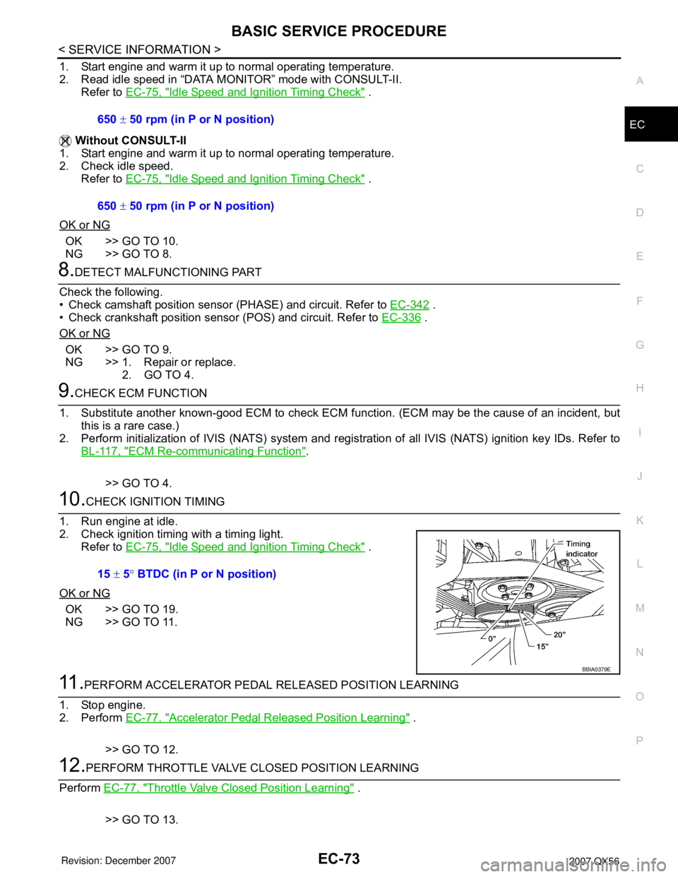
10.CHECK IGNITION TIMING
1. Run engine at idle.
2. Check ignition timing with a timing light.
Refer to EC-75, "
Idle Speed and Ignition Timing Check" .
OK or NG
OK >> GO TO 19.
NG >> GO TO 11.
11 .PERFORM ACCELERATOR PEDAL RELEASED POSITION LEARNING
1. Stop engine.
2. Perform EC-77, "
Accelerator Pedal Released Position Learning" .
>> GO TO 12.
12.PERFORM THROTTLE VALVE CLOSED POSITION LEARNING
Perform EC-77, "
Throttle Valve Closed Position Learning" .
>> GO TO 13. 650 ± 50 rpm (in P or N position)
650 ± 50 rpm (in P or N position)
15 ± 5° BTDC (in P or N position)
BBIA0379E
Page 1157 of 3061
EC-74
< SERVICE INFORMATION >
BASIC SERVICE PROCEDURE
13.PERFORM IDLE AIR VOLUME LEARNING
Refer to EC-78, "
Idle Air Volume Learning" .
Is Idle Air Volume Learning carried out successfully?
Ye s o r N o
Yes >> GO TO 14.
No >> 1. Follow the instruction of Idle Air Volume Learning.
2. GO TO 4.
14.CHECK TARGET IDLE SPEED AGAIN
With CONSULT-II
1. Start engine and warm it up to normal operating temperature.
2. Read idle speed in “DATA MONITOR” mode with CONSULT-II.
Refer to EC-75, "
Idle Speed and Ignition Timing Check" .
Without CONSULT-II
1. Start engine and warm it up to normal operating temperature.
2. Check idle speed.
Refer to EC-75, "
Idle Speed and Ignition Timing Check" .
OK or NG
OK >> GO TO 15.
NG >> GO TO 17.
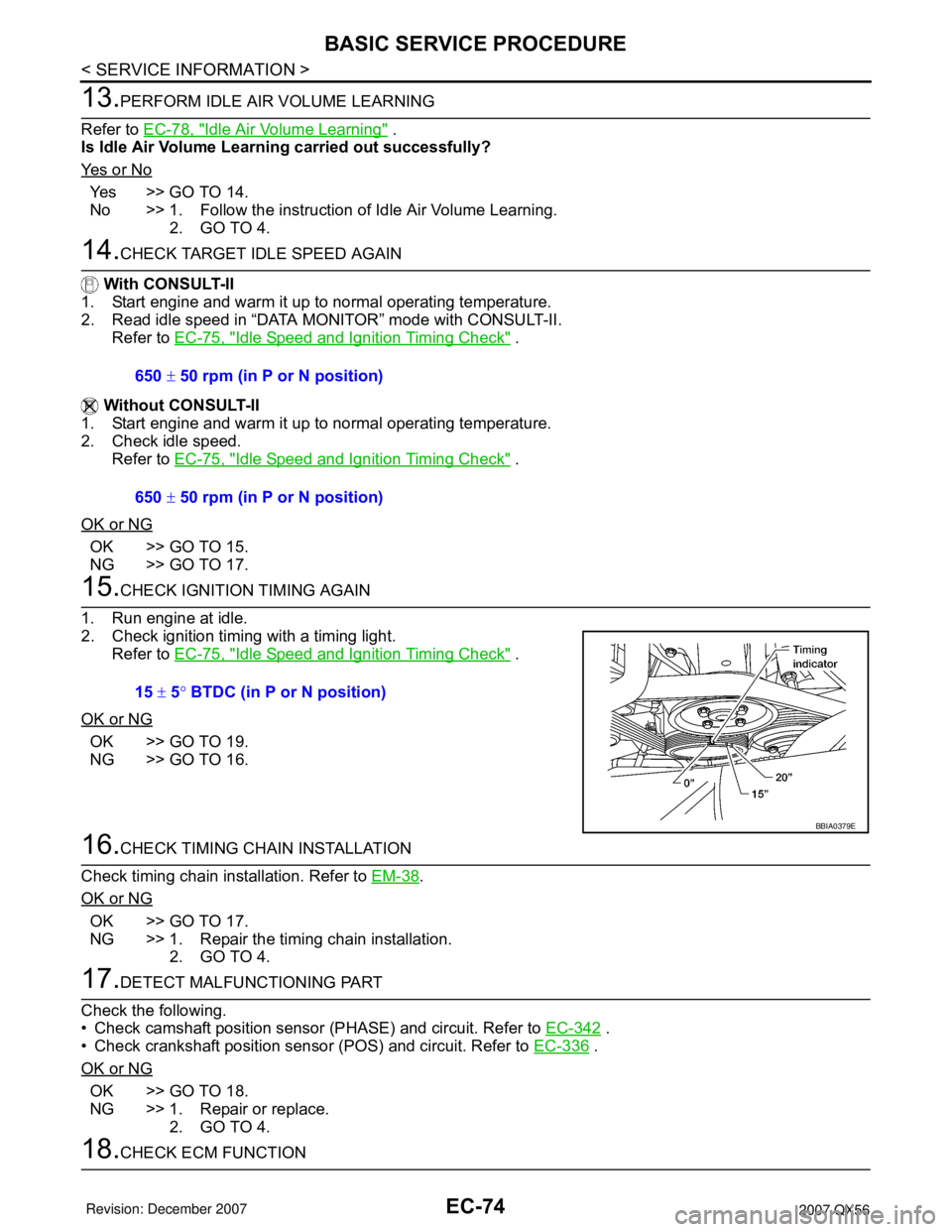
15.CHECK IGNITION TIMING AGAIN
1. Run engine at idle.
2. Check ignition timing with a timing light.
Refer to EC-75, "
Idle Speed and Ignition Timing Check" .
OK or NG
OK >> GO TO 19.
NG >> GO TO 16.
16.CHECK TIMING CHAIN INSTALLATION
Check timing chain installation. Refer to EM-38
.
OK or NG
OK >> GO TO 17.
NG >> 1. Repair the timing chain installation.
2. GO TO 4.
17.DETECT MALFUNCTIONING PART
Check the following.
• Check camshaft position sensor (PHASE) and circuit. Refer to EC-342
.
• Check crankshaft position sensor (POS) and circuit. Refer to EC-336
.
OK or NG
OK >> GO TO 18.
NG >> 1. Repair or replace.
2. GO TO 4.
18.CHECK ECM FUNCTION 650 ± 50 rpm (in P or N position)
650 ± 50 rpm (in P or N position)
15 ± 5° BTDC (in P or N position)
BBIA0379E
Page 1171 of 3061

EC-88
< SERVICE INFORMATION >
TROUBLE DIAGNOSIS
Fail-Safe Chart
INFOID:0000000003531619
When the DTC listed below is detected, the ECM enters fail-safe mode and the MIL lights up.
Priority Detected items (DTC)
1 • U1000 U1001 CAN communication line
• U1010 CAN communication
• P0101 P0102 P0103 Mass air flow sensor
• P0112 P0113 P0127 Intake air temperature sensor
• P0117 P0118 P0125 Engine coolant temperature sensor
• P0122 P0123 P0222 P0223 P1225 P1226 P2135 Throttle position sensor
• P0128 Thermostat function
• P0181 P0182 P0183 Fuel tank temperature sensor
• P0327 P0328 P0332 P0333 Knock sensor
• P0335 Crankshaft position sensor (POS)
• P0340 Camshaft position sensor (PHASE)
• P0460 P0461 P0462 P0463 Fuel level sensor
• P0500 Vehicle speed sensor
• P0605 ECM
• P0643 Sensor power supply
• P0700 TCM
• P0705 Park/neutral position (PNP) switch
• P0850 Park/neutral position (PNP) switch
• P1550 P1551 P1552 P1553 P1554 Battery current sensor
• P1610 - P1615 NATS
• P2122 P2123 P2127 P2128 P2138 Accelerator pedal position sensor
2 • P0031 P0032 P0051 P0052 Air fuel ratio (A/F) sensor 1 heater
• P0037 P0038 P0057 P0058 Heated oxygen sensor 2 heater
• P0075 P0081 Intake valve timing control solenoid valve
• P0130 P0131 P0132 P0133 P0150 P0151 P0152 P0153 P2A00 P2A03 Air fuel ratio (A/F) sensor 1
• P0137 P0138 P0139 P0157 P0158 P0159 Heated oxygen sensor 2
• P0441 EVAP control system purge flow monitoring
• P0443 P0444 P0445 EVAP canister purge volume control solenoid valve
• P0447 P0448 EVAP canister vent control valve
• P0451 P0452 P0453 EVAP control system pressure sensor
• P0550 Power steering pressure sensor
• P0603 ECM power supply
• P0710 P0717 P0720 P0740 P0744 P0745 P1730 P1752 P1754 P1757 P1759 P1762 P1764 P1767 P1769 P1772
P1774 A/T related sensors, solenoid valves and switches
• P1217 Engine over temperature (OVERHEAT)
• P1140 P1145 Intake valve timing control position sensor
• P1805 Brake switch
• P2100 P2103 P2118 Electric throttle control actuator
• P2101 Electric throttle control function
3 • P0011 P0021 Intake valve timing control
• P0171 P0172 P0174 P0175 Fuel injection system function
• P0300 - P0308 Misfire
• P0420 P0430 Three way catalyst function
• P0442 EVAP control system (SMALL LEAK)
• P0455 EVAP control system (GROSS LEAK)
• P0456 EVAP control system (VERY SMALL LEAK)
• P0506 P0507 Idle speed control system
• P1148 P1168 Closed loop control
• P1211 TCS control unit
• P1212 TCS communication line
• P1421 Cold start control
• P1564 ICC/ASCD steering switch
• P1568 ICC command value
• P1572 ICC/ASCD brake switch
• P1574 ICC/ASCD vehicle speed sensor
• P2119 Electric throttle control actuator