2007 INFINITI QX56 712
[x] Cancel search: 712Page 626 of 3061

AV-86
< SERVICE INFORMATION >
NAVIGATION SYSTEM
Wiring Diagram - COMM -
INFOID:0000000003533712
WKWA3600E
Page 1293 of 3061

EC-210
< SERVICE INFORMATION >
DTC P0122, P0123 TP SENSOR
DTC P0122, P0123 TP SENSOR
Component DescriptionINFOID:0000000003531711
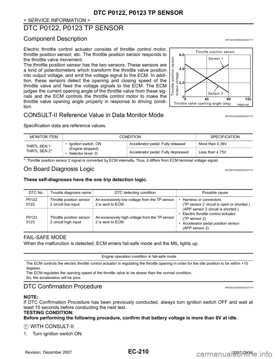
Electric throttle control actuator consists of throttle control motor,
throttle position sensor, etc. The throttle position sensor responds to
the throttle valve movement.
The throttle position sensor has the two sensors. These sensors are
a kind of potentiometers which transform the throttle valve position
into output voltage, and emit the voltage signal to the ECM. In addi-
tion, these sensors detect the opening and closing speed of the
throttle valve and feed the voltage signals to the ECM. The ECM
judges the current opening angle of the throttle valve from these sig-
nals and the ECM controls the throttle control motor to make the
throttle valve opening angle properly in response to driving condi-
tion.
CONSULT-II Reference Value in Data Monitor ModeINFOID:0000000003531712
Specification data are reference values.
*: Throttle position sensor 2 signal is converted by ECM internally. Thus, it differs from ECM terminal voltage signal.
On Board Diagnosis LogicINFOID:0000000003531713
These self-diagnoses have the one trip detection logic.
FA I L - S A F E M O D E
When the malfunction is detected, ECM enters fail-safe mode and the MIL lights up.
DTC Confirmation ProcedureINFOID:0000000003531714
NOTE:
If DTC Confirmation Procedure has been previously conducted, always turn ignition switch OFF and wait at
least 10 seconds before conducting the next test.
TESTING CONDITION:
Before performing the following procedure, confirm that battery voltage is more than 8V at idle.
WITH CONSULT-II
1. Turn ignition switch ON.
PBIB0145E
MONITOR ITEM CONDITION SPECIFICATION
THRTL SEN 1
THRTL SEN 2*• Ignition switch: ON
(Engine stopped)
• Selector lever: DAccelerator pedal: Fully released More than 0.36V
Accelerator pedal: Fully depressed Less than 4.75V
DTC No. Trouble diagnosis name DTC detecting condition Possible cause
P0122
0122Throttle position sensor
2 circuit low inputAn excessively low voltage from the TP sensor
2 is sent to ECM.• Harness or connectors
(TP sensor 2 circuit is open or shorted.)
(APP sensor 2 circuit is shorted.)
• Electric throttle control actuator
(TP sensor 2)
• Accelerator pedal position sensor
(APP sensor 2) P0123
0123Throttle position sensor
2 circuit high inputAn excessively high voltage from the TP sensor
2 is sent to ECM.
Engine operation condition in fail-safe mode
The ECM controls the electric throttle control actuator in regulating the throttle opening in order for the idle position to be within +10
degrees.
The ECM regulates the opening speed of the throttle valve to be slower than the normal condition.
So, the acceleration will be poor.
Page 1714 of 3061

IGNITION SIGNAL
EC-631
< SERVICE INFORMATION >
C
D
E
F
G
H
I
J
K
L
MA
EC
N
P O
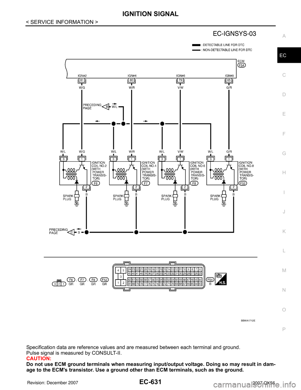
Specification data are reference values and are measured between each terminal and ground.
Pulse signal is measured by CONSULT-II.
CAUTION:
Do not use ECM ground terminals when measuring input/output voltage. Doing so may result in dam-
age to the ECM's transistor. Use a ground other than ECM terminals, such as the ground.
BBWA1712E
Page 3005 of 3061

WT-16
< SERVICE INFORMATION >
TROUBLE DIAGNOSIS
× : Applicable
– : Not applicable
Self-Diagnostic Results Mode
NOTE:
Before performing the self-diagnosis, be sure to register the ID or else the actual malfunction location may be different from that dis-
played on CONSULT-II.
Data Monitor Mode
Rear - Left transmitter××
Rear - Right transmitter××
Warning lamp —×
Vehicle speed××
Buzzer (in combination meter) —×
CAN Communication×× ITEM SELF-DIAGNOSTIC RESULTS DATA MONITOR
Diagnostic item
Diagnostic item is detected when ···Reference
page Program card UED06A or
earlierProgram card UED06B or later
FLAT - TIRE - FL [C1704]
FLAT - TIRE - FR [C1705]
FLAT - TIRE - RR [C1706]
FLAT - TIRE - RL [C1707]LOW - PRESSURE - FL [C1704]
LOW - PRESSURE - FR [C1705]
LOW - PRESSURE - RR [C1706]
LOW - PRESSURE - RL [C1707]FL tire pressure 193 kPa (2.0 kg/cm
2 , 28 psi) or less
FR tire pressure 193 kPa (2.0 kg/cm2 , 28 psi) or less
RR tire pressure 193 kPa (2.0 kg/cm2 , 28 psi) or less
RL tire pressure 193 kPa (2.0 kg/cm2 , 28 psi) or less—
[NO-DATA] - FL [C1708]
[NO-DATA] - FR [C1709]
[NO-DATA] - RR [C1710]
[NO-DATA] - RL [C1711]Data from FL transmitter cannot be received.
Data from FR transmitter cannot be received.
Data from RR transmitter cannot be received.
Data from RL transmitter cannot be received.WT-20
[CHECKSUM- ERR] - FL [C1712]
[CHECKSUM- ERR] - FR [C1713]
[CHECKSUM- ERR] - RR [C1714]
[CHECKSUM- ERR] - RL [C1715]Checksum data from FL transmitter is malfunctioning.
Checksum data from FR transmitter is malfunctioning.
Checksum data from RR transmitter is malfunctioning.
Checksum data from RL transmitter is malfunctioning.WT-20
[PRESSDATA- ERR] - FL [C1716]
[PRESSDATA- ERR] - FR [C1717]
[PRESSDATA- ERR] - RR [C1718]
[PRESSDATA- ERR] - RL [C1719]Air pressure data from FL transmitter is malfunctioning.
Air pressure data from FR transmitter is malfunctioning.
Air pressure data from RR transmitter is malfunctioning.
Air pressure data from RL transmitter is malfunctioning.WT-21
[CODE- ERR] - FL [C1720]
[CODE- ERR] - FR [C1721]
[CODE- ERR] - RR [C1722]
[CODE- ERR] - RL [C1723]Function code data from FL transmitter is malfunctioning.
Function code data from FR transmitter is malfunctioning.
Function code data from RR transmitter is malfunctioning.
Function code data from RL transmitter is malfunctioning.WT-20
[BATT - VOLT - LOW] - FL [C1724]
[BATT - VOLT - LOW] - FR [C1725]
[BATT - VOLT - LOW] - RR [C1726]
[BATT - VOLT - LOW] - RL [C1727]Battery voltage of FL transmitter drops.
Battery voltage of FR transmitter drops.
Battery voltage of RR transmitter drops.
Battery voltage of RL transmitter drops.WT-20
VHCL_SPEED_SIG_ERR [C1729] Vehicle speed signal is in error.WT-21
IGN_CIRCUIT_OPEN [C1735] Vehicle ignition signal is in error.WT-22
MONITOR CONDITION SPECIFICATION
VHCL SPEED Drive vehicle. Vehicle speed (km/h or MPH)
AIR PRESS FL
AIR PRESS FR
AIR PRESS RR
AIR PRESS RL• Drive vehicle for a few minutes.
Tire pressure (kPa or psi) or
• Ignition switch ON and activation tool
is transmitting activation signals.
Page 3009 of 3061

WT-20
< SERVICE INFORMATION >
TROUBLE DIAGNOSIS FOR SELF-DIAGNOSTIC ITEMS
TROUBLE DIAGNOSIS FOR SELF-DIAGNOSTIC ITEMS
Data from Transmitter Not Being ReceivedINFOID:0000000003532704
MALFUNCTION CODE NO. 21, 22, 23 OR 24 (DTC C1708, C1709, C1710 OR C1711)
1.CHECK BCM
Drive for several minutes. Check all tire pressures with CONSULT-II.
Are all tire pressures displayed as 0 kPa?
YES >> GO TO 2.
NO >> GO TO 3.
2.CHECK REMOTE KEYLESS ENTRY RECEIVER CONNECTOR
Check remote keyless entry receiver connector for damage or loose connections.
OK or NG
OK >> Replace BCM, then GO TO 3. Refer to BCS-24, "BCM".
NG >> Repair or replace remote keyless entry receiver connector.
3.PERFORM ID REGISTRATION
Carry out ID registration of all transmitters. Refer to WT-12, "
ID Registration Procedure".
Is there a tire that cannot register ID?
YES >> Replace transmitter of the tire, then GO TO 5. Refer to WT-26, "Transmitter (Pressure Sensor)".
NO >> GO TO 4.
4.DRIVE VEHICLE
1. Drive at a speed of 40 km/h (25 MPH) or more for several minutes without stopping.
2. Check all tire pressures with CONSULT-II within 15 minutes after vehicle speed becomes 17 km/h (11
MPH).
Does
“DATA MONITOR ITEM” display tire pressure as normal without any warning lamp?
YES >> Inspection End.
NO >> GO TO 5.
5.ID REGISTRATION AND VEHICLE DRIVING
1. Carry out ID registration of all transmitters. Refer to WT-12, "
ID Registration Procedure".
2. Drive at a speed of 40 km/h (25 MPH) or more for 3 minutes, and then drive the vehicle at any speed for
10 minutes.
3. Check all tire pressures with CONSULT-II within 5 minutes.
Does
“DATA MONITOR ITEM” display tire pressure as normal without any warning lamp?
YES >> Inspection End.
NO >> GO TO the inspection applicable to DTC.
Transmitter MalfunctionINFOID:0000000003532705
MALFUNCTION CODE NO. 31, 32, 33, 34, 41, 42, 43, 44, 45, 46, 47 OR 48 (DTC C1712, C1713,
C1714, C1715, C1720, C1721, C1722, C1723, C1724, C1725, C1726 OR C1727)
1.PERFORM ID REGISTRATION
1. Carry out ID registration of all transmitters. Refer to WT-12, "
ID Registration Procedure".
2. Drive at a speed of 40 km/h (25 MPH) or more for 3 minutes, and then drive the vehicle at any speed for
10 minutes.
>> GO TO 2.
2.REPLACE TRANSMITTER
1. Check low tire pressure warning lamp again for flashing, replace malfunctioning transmitter. Refer to WT-
26, "Transmitter (Pressure Sensor)".
2. Carry out ID registration of all transmitters. Refer to WT-12, "
ID Registration Procedure".
Page 3014 of 3061

TROUBLE DIAGNOSIS FOR SYMPTOMS
WT-25
< SERVICE INFORMATION >
C
D
F
G
H
I
J
K
L
MA
B
WT
N
O
P
OK or NG
OK >> Replace BCM. Refer to BCS-24, "BCM" .
NG >> Repair or replace harness connector.
Hazard Warning Lamps Flash When Ignition Switch Is Turned OnINFOID:0000000003532711
DIAGNOSTIC PROCEDURE
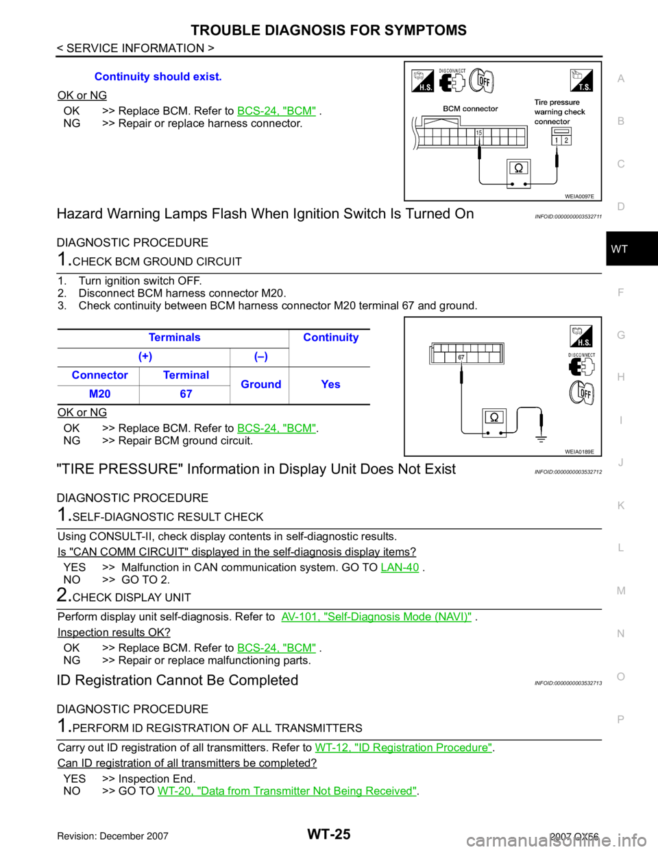
1.CHECK BCM GROUND CIRCUIT
1. Turn ignition switch OFF.
2. Disconnect BCM harness connector M20.
3. Check continuity between BCM harness connector M20 terminal 67 and ground.
OK or NG
OK >> Replace BCM. Refer to BCS-24, "BCM".
NG >> Repair BCM ground circuit.
"TIRE PRESSURE" Information in Display Unit Does Not ExistINFOID:0000000003532712
DIAGNOSTIC PROCEDURE
1.SELF-DIAGNOSTIC RESULT CHECK
Using CONSULT-II, check display contents in self-diagnostic results.
Is "CAN COMM CIRCUIT" displayed in the self-diagnosis display items?
YES >> Malfunction in CAN communication system. GO TO LAN-40 .
NO >> GO TO 2.
2.CHECK DISPLAY UNIT
Perform display unit self-diagnosis. Refer to AV-101, "
Self-Diagnosis Mode (NAVI)" .
Inspection results OK?
OK >> Replace BCM. Refer to BCS-24, "BCM" .
NG >> Repair or replace malfunctioning parts.
ID Registration Cannot Be CompletedINFOID:0000000003532713
DIAGNOSTIC PROCEDURE
1.PERFORM ID REGISTRATION OF ALL TRANSMITTERS
Carry out ID registration of all transmitters. Refer to WT-12, "
ID Registration Procedure".
Can ID registration of all transmitters be completed?
YES >> Inspection End.
NO >> GO TO WT-20, "
Data from Transmitter Not Being Received". Continuity should exist.
WEIA0097E
Terminals Continuity
(+) (–)
Connector Terminal
Ground Yes
M20 67
WEIA0189E