2007 INFINITI QX56 coolant temperature
[x] Cancel search: coolant temperaturePage 2016 of 3061

GI-50
< SERVICE INFORMATION >
TERMINOLOGY
TERMINOLOGY
SAE J1930 Terminology ListINFOID:0000000003531507
All emission related terms used in this publication in accordance with SAE J1930 are listed. Accordingly, new
terms, new acronyms/abbreviations and old terms are listed in the following chart.
NEW TERMNEW ACRONYM /
ABBREVIATIONOLD TERM
Air cleaner ACL Air cleaner
Barometric pressure BARO ***
Barometric pressure sensor-BCDD BAROS-BCDD BCDD
Camshaft position CMP ***
Camshaft position sensor CMPS Crank angle sensor
Canister *** Canister
Carburetor CARB Carburetor
Charge air cooler CAC Intercooler
Closed loop CL Closed loop
Closed throttle position switch CTP switch Idle switch
Clutch pedal position switch CPP switch Clutch switch
Continuous fuel injection system CFI system ***
Continuous trap oxidizer system CTOX system ***
Crankshaft position CKP ***
Crankshaft position sensor CKPS ***
Data link connector DLC ***
Data link connector for CONSULT-II DLC for CONSULT-II Diagnostic connector for CONSULT-II
Diagnostic test mode DTM Diagnostic mode
Diagnostic test mode selector DTM selector Diagnostic mode selector
Diagnostic test mode I DTM I Mode I
Diagnostic test mode II DTM II Mode II
Diagnostic trouble code DTC Malfunction code
Direct fuel injection system DFI system ***
Distributor ignition system DI system Ignition timing control
Early fuel evaporation-mixture heater EFE-mixture heater Mixture heater
Early fuel evaporation system EFE system Mixture heater control
Electrically erasable programmable read
only memoryEEPROM ***
Electronic ignition system EI system Ignition timing control
Engine control EC ***
Engine control module ECM ECCS control unit
Engine coolant temperature ECT Engine temperature
Engine coolant temperature sensor ECTS Engine temperature sensor
Engine modification EM ***
Engine speed RPM Engine speed
Erasable programmable read only memory EPROM ***
Evaporative emission canister EVAP canister Canister
Evaporative emission system EVAP system Canister control solenoid valve
Exhaust gas recirculation valve EGR valve EGR valve
Page 2108 of 3061
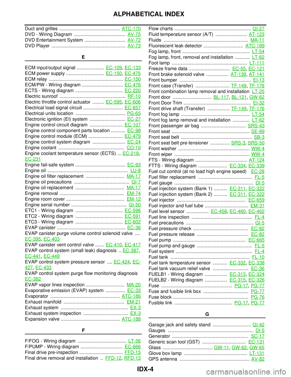
IDX-4
ALPHABETICAL INDEX
Duct and grilles .............................................. ATC-170
DVD - Wiring Diagram ....................................... AV-75
DVD Entertainment System ............................... AV-72
DVD Player ........................................................ AV-73
E
ECM input/output signal ..................... EC-109
, EC-133
ECM power supply ............................. EC-150, EC-475
ECM relay ........................................................ EC-150
ECM/PW - Wiring diagram ............................... EC-476
ECTS - Wiring diagram .................................... EC-220
Electric sunroof .................................................. RF-10
Electric throttle control actuator ......... EC-595, EC-606
Electrical load signal circuit .............................. EC-657
Electrical units location ...................................... PG-65
Electronic ignition (EI) system ........................... EC-27
Engine control circuit diagram ......................... EC-107
Engine control component parts location ........... EC-98
Engine control module (ECM) .......................... EC-479
Engine control system diagram ......................... EC-24
Engine coolant .................................................. CO-10
Engine coolant temperature sensor (ECTS) ... EC-218,
EC-231
Engine fail-safe system ...................................... EC-93
Engine oil ............................................................. LU-8
Engine oil filter replacement ............................. MA-17
Engine oil precautions .......................................... GI-7
Engine oil replacement ..................................... MA-17
Engine removal ................................................. EM-74
Engine room cover ............................................ EM-12
Engine serial number .......................................... GI-50
ETC1 - Wiring diagram .................................... EC-596
ETC2 - Wiring diagram .................................... EC-591
ETC3 - Wiring diagram .................................... EC-602
EVAP canister .................................................... EC-36
EVAP canister purge volume control solenoid valve ....
EC-395
, EC-403
EVAP canister vent control valve ....... EC-410, EC-417
EVAP control system (small leak) diagnosis .. EC-387,
EC-441
, EC-449
EVAP control system pressure sensor .... EC-424, EC-
427, EC-433
EVAP control system purge flow monitoring diagnosis
EC-382
EVAP vapor lines inspection ............................. MA-20
Evaporative emission (EVAP) system ............... EC-33
Evaporator ..................................................... ATC-186
Exhaust manifold .............................................. EM-21
Exhaust system ................................................... EX-3
Exhaust system inspection .................................. EX-3
Expansion valve ............................................. ATC-188
F
F/FOG - Wiring diagram ..................................... LT-56
F/PUMP - Wiring diagram ................................ EC-666
Final drive pre-inspection ................................. FFD-15
Final drive removal and installation .. FFD-12, RFD-13
Flow charts .......................................................... GI-27
Fluid temperature sensor (A/T) ........................ AT-123
Fluids ................................................................ MA-11
Fluorescent leak detector .............................. ATC-189
Fog lamp, front ................................................... LT-54
Fog lamp, front, removal and installation ........... LT-62
Foot lamp ......................................................... LT-111
Freeze frame data ............................... EC-55, EC-121
Front brake solenoid valve ................. AT-139, AT-141
Front bumper ...................................................... EI-13
Front case (Transfer) .......................... TF-149, TF-176
Front combination lamp removal and installation LT-25
Front door ............................. BL-117, BL-121, GW-62
Front Door Trim ................................................... EI-32
Front drive shaft (Transfer) ................. TF-149, TF-176
Front fog lamp .................................................... LT-54
Front fog lamp removal and installation ............. LT-62
Front passenger air bag .................................. SRS-43
Front seat ........................................................... SE-89
Front seat belt ...................................................... SB-3
Front seat belt pre-tensioner ............... SRS-3, SRS-50
Front washer ...................................................... WW-4
Front wiper ......................................................... WW-4
FTS - Wiring diagram ....................................... AT-124
FTTS - Wiring diagram ...................... EC-334, EC-339
Fuel cut control (at no load high engine speed) EC-28
Fuel filter replacement ......................................... FL-5
Fuel gauge ............................................................ DI-5
Fuel injection system (Bank 1) .......... EC-311, EC-322
Fuel injection system (Bank 2) .......... EC-311, EC-322
Fuel injector .................................................... EC-659
Fuel injector and fuel tube ................................. EM-31
Fuel level sensor ................. EC-458, EC-460, EC-462
Fuel line inspection .............................................. FL-4
Fuel precautions ................................................... GI-5
Fuel pressure check .......................................... EC-82
Fuel pressure release ....................................... EC-82
Fuel pump ....................................................... EC-665
Fuel pump and gauge .......................................... FL-5
Fuel system .......................................................... FL-4
Fuel tank ............................................................ FL-10
Fuel tank temperature sensor ........... EC-332, EC-338
Fuel tank vacuum relief valve ........................... EC-36
FUELB1 - Wiring diagram ................. EC-313, EC-324
FUELB2 - Wiring diagram ................. EC-315, EC-326
Fuse ...................................................... PG-17, PG-77
Fuse and fusible link box .................................. PG-77
Fuse block ......................................................... PG-76
Fusible link ............................................ PG-17, PG-77
G
Garage jack and safety stand ............................. GI-42
Gauges ................................................................. DI-5
Generator .......................................................... SC-17
Generic scan tool (GST) ................................. EC-131
Glass ...................................... GW-11, GW-62, GW-65
Glove box lamp ................................................ LT-131
GPS antenna ..................................................... AV-82
Page 2175 of 3061
![INFINITI QX56 2007 Factory Service Manual LAN-44
< SERVICE INFORMATION >[CAN]
TROUBLE DIAGNOSIS
CAN System Specification Chart
INFOID:0000000003533627
Determine CAN system type from the following specification chart. Then choose the correct d INFINITI QX56 2007 Factory Service Manual LAN-44
< SERVICE INFORMATION >[CAN]
TROUBLE DIAGNOSIS
CAN System Specification Chart
INFOID:0000000003533627
Determine CAN system type from the following specification chart. Then choose the correct d](/manual-img/42/57029/w960_57029-2174.png)
LAN-44
< SERVICE INFORMATION >[CAN]
TROUBLE DIAGNOSIS
CAN System Specification Chart
INFOID:0000000003533627
Determine CAN system type from the following specification chart. Then choose the correct diagnosis sheet.
NOTE:
Refer to LAN-14, "
Trouble Diagnosis Procedure" for how to use CAN system specification chart.
X: Applicable
VEHICLE EQUIPMENT IDENTIFICATION INFORMATION
NOTE:
Check CAN system type from the vehicle shape and equipment.
CAN Communication Signal ChartINFOID:0000000003533628
Refer to LAN-13, "How to Use CAN Communication Signal Chart" for how to use CAN communication signal
chart.
TYPE 1/TYPE 2
NOTE:
Refer to LAN-37, "
Abbreviation List" for the abbreviations of the connecting units.
T: Transmit R: Receive
Body typeWagon
Axle 2WD AWD
EngineVK56DE
Transmission A/T
Brake controlVDC
ICC system X X
CAN system type 1234
Diagnosis sheetLAN-57
LAN-58LAN-59LAN-60
CAN communication signal chartLAN-44, "CAN Communication Sig-
nal Chart"
LAN-44, "CAN Communication Sig-
nal Chart"
BKIA0219E
Signal name/Connecting unitECM
TCM
LASER
ICC
ADP
BCM
DISP
HVAC
M&A
STRG
ABS
IPDM-E
A/C compressor request signal TR
Accelerator pedal position signal T R R R
ASCD CRUISE lamp signal T R
ASCD OD cancel request signal T R
ASCD operation signal T R
ASCD SET lamp signal T R
Battery voltage signal T R
Closed throttle position signal T R R
Cooling fan speed request signal TR
Engine coolant temperature signal T R R
Page 2178 of 3061
![INFINITI QX56 2007 Factory Service Manual TROUBLE DIAGNOSIS
LAN-47
< SERVICE INFORMATION >[CAN]
C
D
E
F
G
H
I
J
L
MA
B
LAN
N
O
P
Cooling fan speed request signal TR
Engine coolant temperature signal T R R
Engine speed signal T R R R R R R R
E INFINITI QX56 2007 Factory Service Manual TROUBLE DIAGNOSIS
LAN-47
< SERVICE INFORMATION >[CAN]
C
D
E
F
G
H
I
J
L
MA
B
LAN
N
O
P
Cooling fan speed request signal TR
Engine coolant temperature signal T R R
Engine speed signal T R R R R R R R
E](/manual-img/42/57029/w960_57029-2177.png)
TROUBLE DIAGNOSIS
LAN-47
< SERVICE INFORMATION >[CAN]
C
D
E
F
G
H
I
J
L
MA
B
LAN
N
O
P
Cooling fan speed request signal TR
Engine coolant temperature signal T R R
Engine speed signal T R R R R R R R
Engine status signal T R
Fuel consumption monitor signalTR
RT
ICC steering switch signal T R
Malfunction indicator lamp signal T R
Wide open throttle position signal T R
A/T CHECK indicator lamp signal T R
A/T fluid temperature sensor signal T R
A/T position indicator lamp signal T R R R
A/T self-diagnosis signal R T
Current gear position signal T R R
Output shaft revolution signal R T R R
P range signal T R R R R
Turbine revolution signal R T R
ICC sensor signal T R
Buzzer output signalTR
TR
ICC OD cancel request signal R R T
ICC operation signal R R T
ICC system display signal T R
System setting signalTR
RT
A/C switch signal R T R
Blower fan motor switch signal R T
Day time running light request signal T R R
Door switch signal R T R R R
Front fog light request signal T R
Front wiper request signal R T R
High beam request signal T R R
Horn chirp signal T R
Ignition switch signal R T R
Key fob door unlock signal R T
Key fob ID signal R T
Key switch signal R T
Low beam request signal T R
Position light request signal T R R
Rear window defogger switch signal T R R
Sleep wake up signal R T R R
Theft warning horn request signal T R
Tire pressure data signal T RSignal name/Connecting unit
ECM
TCM
LASER
ICC
ADP
BCM
DISP
HVAC
M&A
STRG
4WD
ABS
IPDM-E
Page 2367 of 3061
GENERAL MAINTENANCE
MA-5
< SERVICE INFORMATION >
C
D
E
F
G
H
I
J
K
MA
B
MA
N
O
P
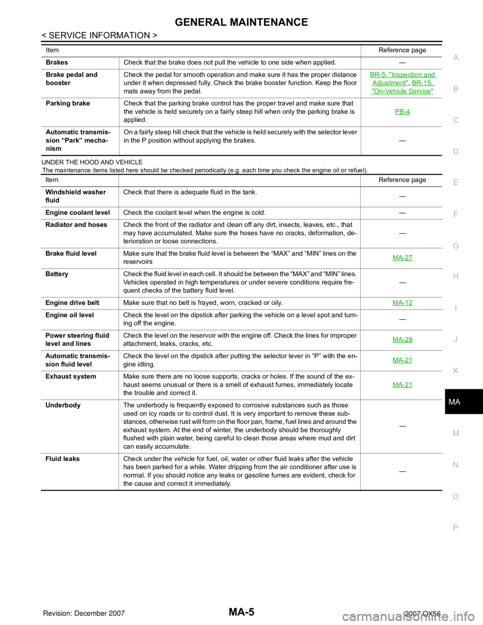
UNDER THE HOOD AND VEHICLE
The maintenance items listed here should be checked periodically (e.g. each time you check the engine oil or refuel).
BrakesCheck that the brake does not pull the vehicle to one side when applied. —
Brake pedal and
boosterCheck the pedal for smooth operation and make sure it has the proper distance
under it when depressed fully. Check the brake booster function. Keep the floor
mats away from the pedal.BR-5, "
Inspection and
Adjustment", BR-15,
"On-Vehicle Service"
Parking brakeCheck that the parking brake control has the proper travel and make sure that
the vehicle is held securely on a fairly steep hill when only the parking brake is
applied.PB-4
Automatic transmis-
sion “Park” mecha-
nismOn a fairly steep hill check that the vehicle is held securely with the selector lever
in the P position without applying the brakes. — ItemReference page
ItemReference page
Windshield washer
fluidCheck that there is adequate fluid in the tank.
—
Engine coolant levelCheck the coolant level when the engine is cold. —
Radiator and hosesCheck the front of the radiator and clean off any dirt, insects, leaves, etc., that
may have accumulated. Make sure the hoses have no cracks, deformation, de-
terioration or loose connections.—
Brake fluid levelMake sure that the brake fluid level is between the “MAX” and “MIN” lines on the
reservoirsMA-27
BatteryCheck the fluid level in each cell. It should be between the “MAX” and “MIN” lines.
Vehicles operated in high temperatures or under severe conditions require fre-
quent checks of the battery fluid level.—
Engine drive beltMake sure that no belt is frayed, worn, cracked or oily.MA-12
Engine oil levelCheck the level on the dipstick after parking the vehicle on a level spot and turn-
ing off the engine.—
Power steering fluid
level and linesCheck the level on the reservoir with the engine off. Check the lines for improper
attachment, leaks, cracks, etc.MA-28
Automatic transmis-
sion fluid levelCheck the level on the dipstick after putting the selector lever in “P” with the en-
gine idling.MA-21
Exhaust systemMake sure there are no loose supports, cracks or holes. If the sound of the ex-
haust seems unusual or there is a smell of exhaust fumes, immediately locate
the trouble and correct it.MA-21
UnderbodyThe underbody is frequently exposed to corrosive substances such as those
used on icy roads or to control dust. It is very important to remove these sub-
stances, otherwise rust will form on the floor pan, frame, fuel lines and around the
exhaust system. At the end of winter, the underbody should be thoroughly
flushed with plain water, being careful to clean those areas where mud and dirt
can easily accumulate.—
Fluid leaksCheck under the vehicle for fuel, oil, water or other fluid leaks after the vehicle
has been parked for a while. Water dripping from the air conditioner after use is
normal. If you should notice any leaks or gasoline fumes are evident, check for
the cause and correct it immediately.—
Page 2368 of 3061
MA-6
< SERVICE INFORMATION >
PERIODIC MAINTENANCE
PERIODIC MAINTENANCE
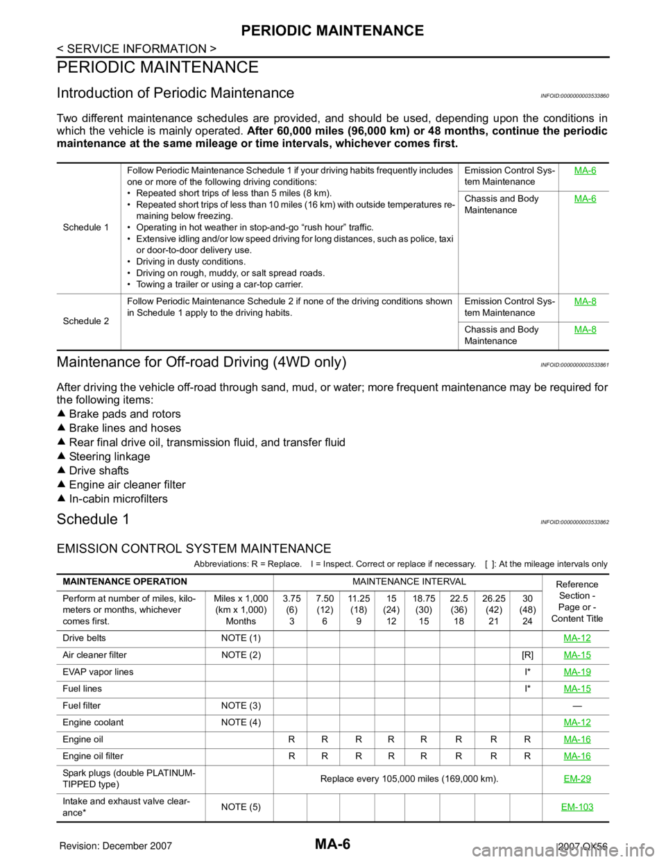
Introduction of Periodic MaintenanceINFOID:0000000003533860
Two different maintenance schedules are provided, and should be used, depending upon the conditions in
which the vehicle is mainly operated. After 60,000 miles (96,000 km) or 48 months, continue the periodic
maintenance at the same mileage or time intervals, whichever comes first.
Maintenance for Off-road Driving (4WD only)INFOID:0000000003533861
After driving the vehicle off-road through sand, mud, or water; more frequent maintenance may be required for
the following items:
Brake pads and rotors
Brake lines and hoses
Rear final drive oil, transmission fluid, and transfer fluid
Steering linkage
Drive shafts
Engine air cleaner filter
In-cabin microfilters
Schedule 1INFOID:0000000003533862
EMISSION CONTROL SYSTEM MAINTENANCE
Abbreviations: R = Replace. I = Inspect. Correct or replace if necessary. [ ]: At the mileage intervals only
Schedule 1Follow Periodic Maintenance Schedule 1 if your driving habits frequently includes
one or more of the following driving conditions:
• Repeated short trips of less than 5 miles (8 km).
• Repeated short trips of less than 10 miles (16 km) with outside temperatures re-
maining below freezing.
• Operating in hot weather in stop-and-go “rush hour” traffic.
• Extensive idling and/or low speed driving for long distances, such as police, taxi
or door-to-door delivery use.
• Driving in dusty conditions.
• Driving on rough, muddy, or salt spread roads.
• Towing a trailer or using a car-top carrier.Emission Control Sys-
tem MaintenanceMA-6
Chassis and Body
MaintenanceMA-6
Schedule 2Follow Periodic Maintenance Schedule 2 if none of the driving conditions shown
in Schedule 1 apply to the driving habits.Emission Control Sys-
tem MaintenanceMA-8Chassis and Body
MaintenanceMA-8
MAINTENANCE OPERATIONMAINTENANCE INTERVAL
Reference
Section -
Page or -
Content Title Perform at number of miles, kilo-
meters or months, whichever
comes first.Miles x 1,000
(km x 1,000)
Months3.75
(6)
37.50
(12)
611 . 2 5
(18)
915
(24)
1218.75
(30)
1522.5
(36)
1826.25
(42)
2130
(48)
24
Drive belts NOTE (1)MA-12
Air cleaner filter NOTE (2) [R]MA-15
EVAP vapor linesI*MA-19
Fuel linesI*MA-15
Fuel filter NOTE (3)—
Engine coolant NOTE (4)MA-12
Engine oil R R R R R R R RMA-16
Engine oil filter R R R R R R R RMA-16
Spark plugs (double PLATINUM-
TIPPED type)Replace every 105,000 miles (169,000 km).EM-29
Intake and exhaust valve clear-
ance*NOTE (5)EM-103
Page 2372 of 3061
MA-10
< SERVICE INFORMATION >
RECOMMENDED FLUIDS AND LUBRICANTS
RECOMMENDED FLUIDS AND LUBRICANTS
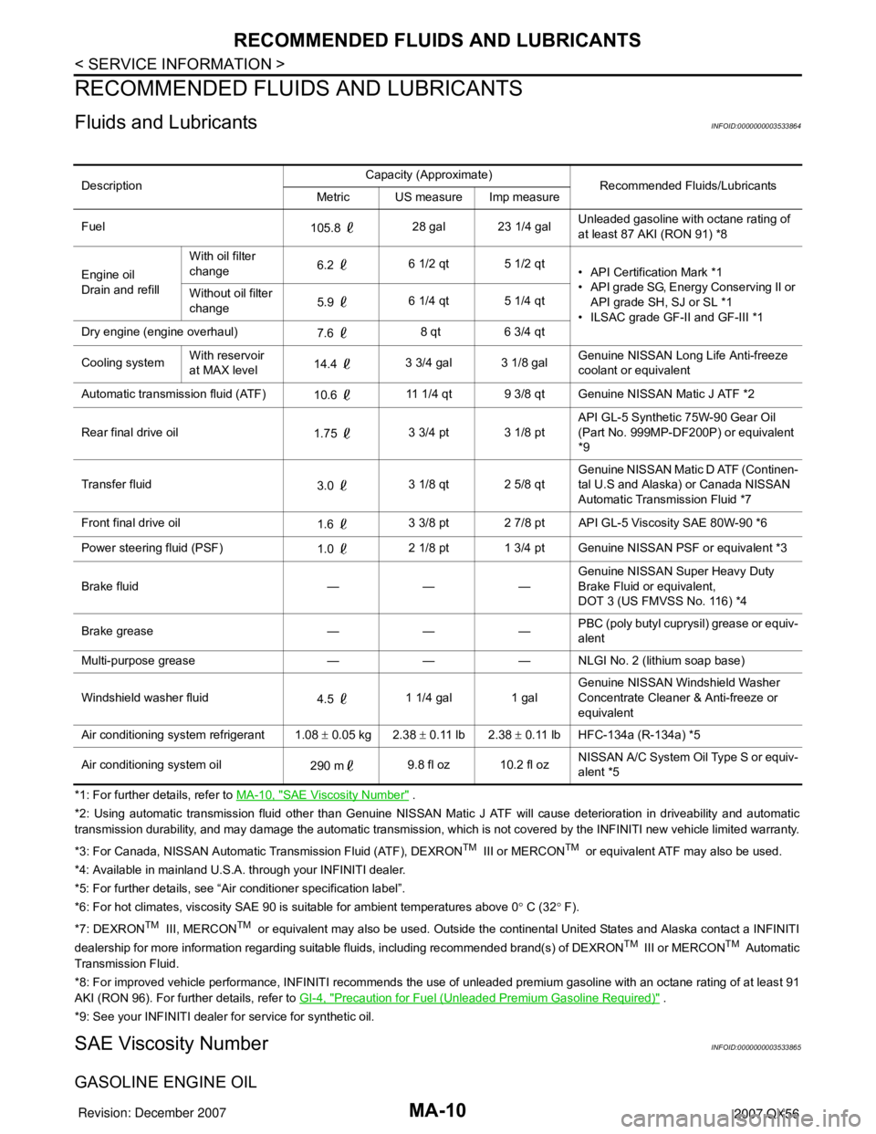
Fluids and LubricantsINFOID:0000000003533864
*1: For further details, refer to MA-10, "SAE Viscosity Number" .
*2: Using automatic transmission fluid other than Genuine NISSAN Matic J ATF will cause deterioration in driveability and automatic
transmission durability, and may damage the automatic transmission, which is not covered by the INFINITI new vehicle limited warranty.
*3: For Canada, NISSAN Automatic Transmission Fluid (ATF), DEXRON
TM III or MERCONTM or equivalent ATF may also be used.
*4: Available in mainland U.S.A. through your INFINITI dealer.
*5: For further details, see “Air conditioner specification label”.
*6: For hot climates, viscosity SAE 90 is suitable for ambient temperatures above 0° C (32° F).
*7: DEXRON
TM III, MERCONTM or equivalent may also be used. Outside the continental United States and Alaska contact a INFINITI
dealership for more information regarding suitable fluids, including recommended brand(s) of DEXRONTM III or MERCONTM Automatic
Transmission Fluid.
*8: For improved vehicle performance, INFINITI recommends the use of unleaded premium gasoline with an octane rating of at least 91
AKI (RON 96). For further details, refer to GI-4, "
Precaution for Fuel (Unleaded Premium Gasoline Required)" .
*9: See your INFINITI dealer for service for synthetic oil.
SAE Viscosity NumberINFOID:0000000003533865
GASOLINE ENGINE OIL
DescriptionCapacity (Approximate)
Recommended Fluids/Lubricants
Metric US measure Imp measure
Fuel
105.8 28 gal 23 1/4 galUnleaded gasoline with octane rating of
at least 87 AKI (RON 91) *8
Engine oil
Drain and refillWith oil filter
change6.2 6 1/2 qt 5 1/2 qt
• API Certification Mark *1
• API grade SG, Energy Conserving II or
API grade SH, SJ or SL *1
• ILSAC grade GF-II and GF-III *1 Without oil filter
change5.9 6 1/4 qt 5 1/4 qt
Dry engine (engine overhaul)
7.6 8 qt 6 3/4 qt
Cooling systemWith reservoir
at MAX level14.4 3 3/4 gal 3 1/8 galGenuine NISSAN Long Life Anti-freeze
coolant or equivalent
Automatic transmission fluid (ATF)
10.6 11 1/4 qt 9 3/8 qt Genuine NISSAN Matic J ATF *2
Rear final drive oil
1.75 3 3/4 pt 3 1/8 ptAPI GL-5 Synthetic 75W-90 Gear Oil
(Part No. 999MP-DF200P) or equivalent
*9
Transfer fluid
3.0 3 1/8 qt 2 5/8 qtGenuine NISSAN Matic D ATF (Continen-
tal U.S and Alaska) or Canada NISSAN
Automatic Transmission Fluid *7
Front final drive oil
1.6 3 3/8 pt 2 7/8 pt API GL-5 Viscosity SAE 80W-90 *6
Power steering fluid (PSF)
1.0 2 1/8 pt 1 3/4 pt Genuine NISSAN PSF or equivalent *3
Brake fluid — — —Genuine NISSAN Super Heavy Duty
Brake Fluid or equivalent,
DOT 3 (US FMVSS No. 116) *4
Brake grease — — —PBC (poly butyl cuprysil) grease or equiv-
alent
Multi-purpose grease — — — NLGI No. 2 (lithium soap base)
Windshield washer fluid
4.5 1 1/4 gal 1 galGenuine NISSAN Windshield Washer
Concentrate Cleaner & Anti-freeze or
equivalent
Air conditioning system refrigerant 1.08 ± 0.05 kg 2.38 ± 0.11 lb 2.38 ± 0.11 lb HFC-134a (R-134a) *5
Air conditioning system oil
290 m9.8 fl oz 10.2 fl ozNISSAN A/C System Oil Type S or equiv-
alent *5
Page 2373 of 3061
RECOMMENDED FLUIDS AND LUBRICANTS
MA-11
< SERVICE INFORMATION >
C
D
E
F
G
H
I
J
K
MA
B
MA
N
O
P
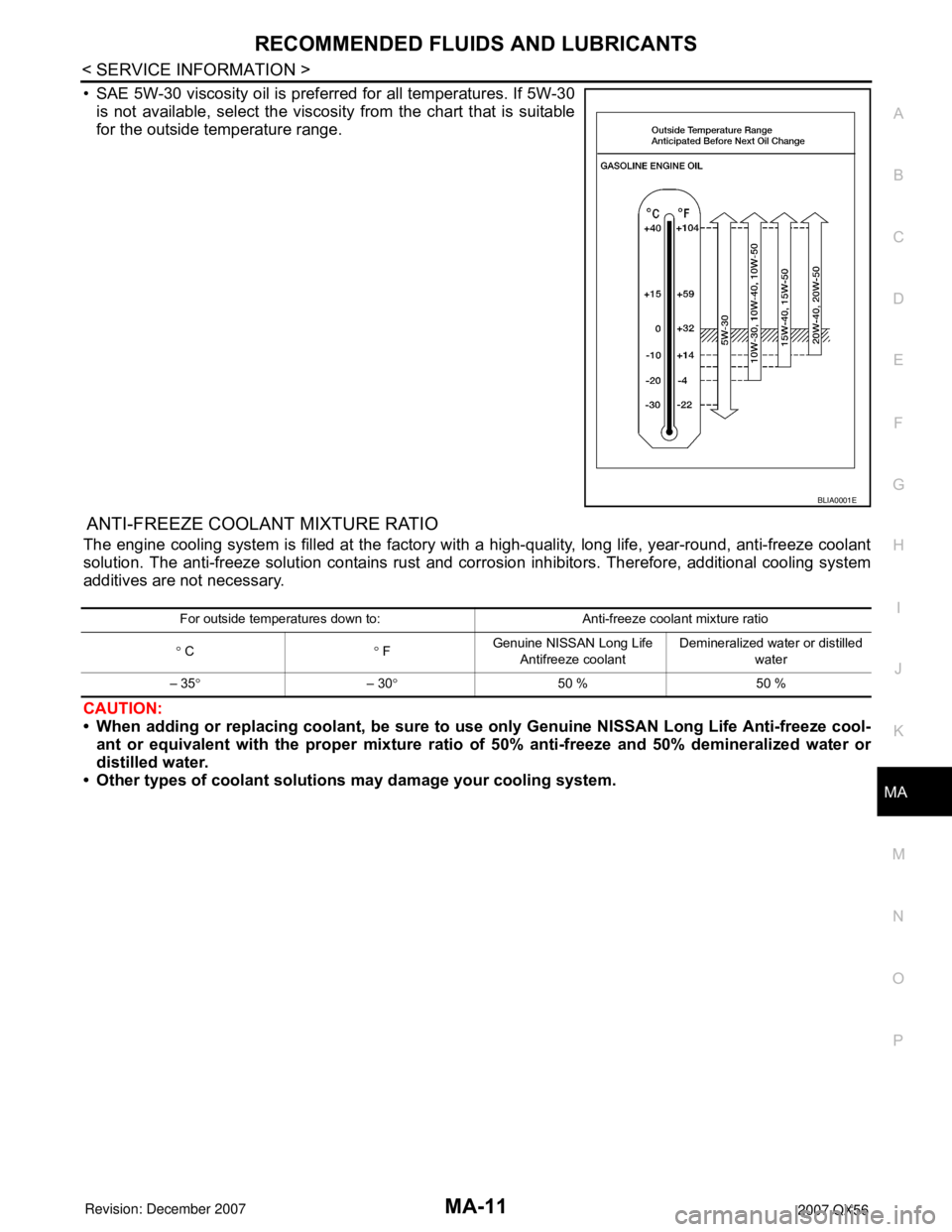
• SAE 5W-30 viscosity oil is preferred for all temperatures. If 5W-30
is not available, select the viscosity from the chart that is suitable
for the outside temperature range.
ANTI-FREEZE COOLANT MIXTURE RATIO
The engine cooling system is filled at the factory with a high-quality, long life, year-round, anti-freeze coolant
solution. The anti-freeze solution contains rust and corrosion inhibitors. Therefore, additional cooling system
additives are not necessary.
CAUTION:
• When adding or replacing coolant, be sure to use only Genuine NISSAN Long Life Anti-freeze cool-
ant or equivalent with the proper mixture ratio of 50% anti-freeze and 50% demineralized water or
distilled water.
• Other types of coolant solutions may damage your cooling system.
BLIA0001E
For outside temperatures down to: Anti-freeze coolant mixture ratio
° C° FGenuine NISSAN Long Life
Antifreeze coolant Demineralized water or distilled
water
– 35°– 30°50 % 50 %