Page 2374 of 3061

MA-12
< SERVICE INFORMATION >
ENGINE MAINTENANCE
ENGINE MAINTENANCE
Checking Drive BeltsINFOID:0000000003533866
WARNING:
Be sure to perform when the engine is stopped.
1. Remove air duct and resonator assembly (inlet) when inspecting drive belt.
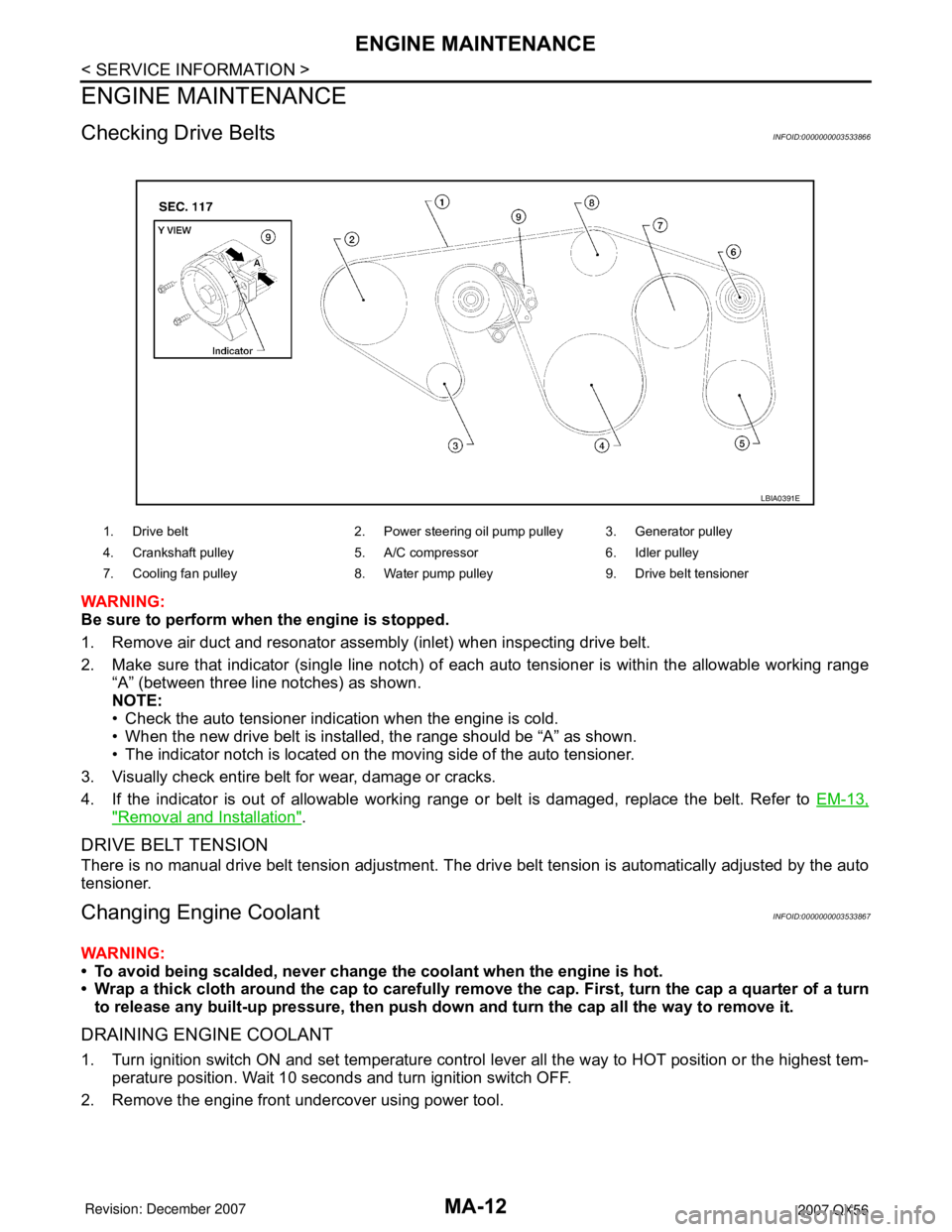
2. Make sure that indicator (single line notch) of each auto tensioner is within the allowable working range
“A” (between three line notches) as shown.
NOTE:
• Check the auto tensioner indication when the engine is cold.
• When the new drive belt is installed, the range should be “A” as shown.
• The indicator notch is located on the moving side of the auto tensioner.
3. Visually check entire belt for wear, damage or cracks.
4. If the indicator is out of allowable working range or belt is damaged, replace the belt. Refer to EM-13,
"Removal and Installation".
DRIVE BELT TENSION
There is no manual drive belt tension adjustment. The drive belt tension is automatically adjusted by the auto
tensioner.
Changing Engine CoolantINFOID:0000000003533867
WARNING:
• To avoid being scalded, never change the coolant when the engine is hot.
• Wrap a thick cloth around the cap to carefully remove the cap. First, turn the cap a quarter of a turn
to release any built-up pressure, then push down and turn the cap all the way to remove it.
DRAINING ENGINE COOLANT
1. Turn ignition switch ON and set temperature control lever all the way to HOT position or the highest tem-
perature position. Wait 10 seconds and turn ignition switch OFF.
2. Remove the engine front undercover using power tool.
1. Drive belt 2. Power steering oil pump pulley 3. Generator pulley
4. Crankshaft pulley 5. A/C compressor 6. Idler pulley
7. Cooling fan pulley 8. Water pump pulley 9. Drive belt tensioner
LBIA0391E
Page 2377 of 3061

ENGINE MAINTENANCE
MA-15
< SERVICE INFORMATION >
C
D
E
F
G
H
I
J
K
MA
B
MA
N
O
P
2. Fill the radiator and the reservoir tank (to the “MAX” line), with water. Reinstall the radiator cap and leave
the vented reservoir cap off.
3. Run the engine until it reaches normal operating temperature.
4. Press the engine accelerator two or three times under no-load.
5. Stop the engine and wait until it cools down.
6. Drain the water from the engine cooling system. Refer to CO-9, "
Changing Engine Coolant" .
7. Repeat steps 2 through 6 until clear water begins to drain from the radiator.
Checking Fuel LineINFOID:0000000003533868
Inspect the fuel lines and fuel tank for improper mounting, leaks,
cracks, damage, loose connections, chafing, or deterioration.
As necessary, repair or replace any faulty parts.
Changing Fuel FilterINFOID:0000000003533869
The fuel filter is part of the fuel level sensor unit, fuel filter and fuel pump assembly. Refer to FL-5 .
WARNING:
Before replacing the fuel filter, release the fuel pressure from the fuel system. Refer to EC-80, "
Fuel
Pressure Check".
Changing Engine Air Cleaner FilterINFOID:0000000003533870
VISCOUS PAPER TYPE
NOTE:
• The viscous paper type filter does not need cleaning between replacement intervals.
• Replace the air filter as necessary for required maintenance.
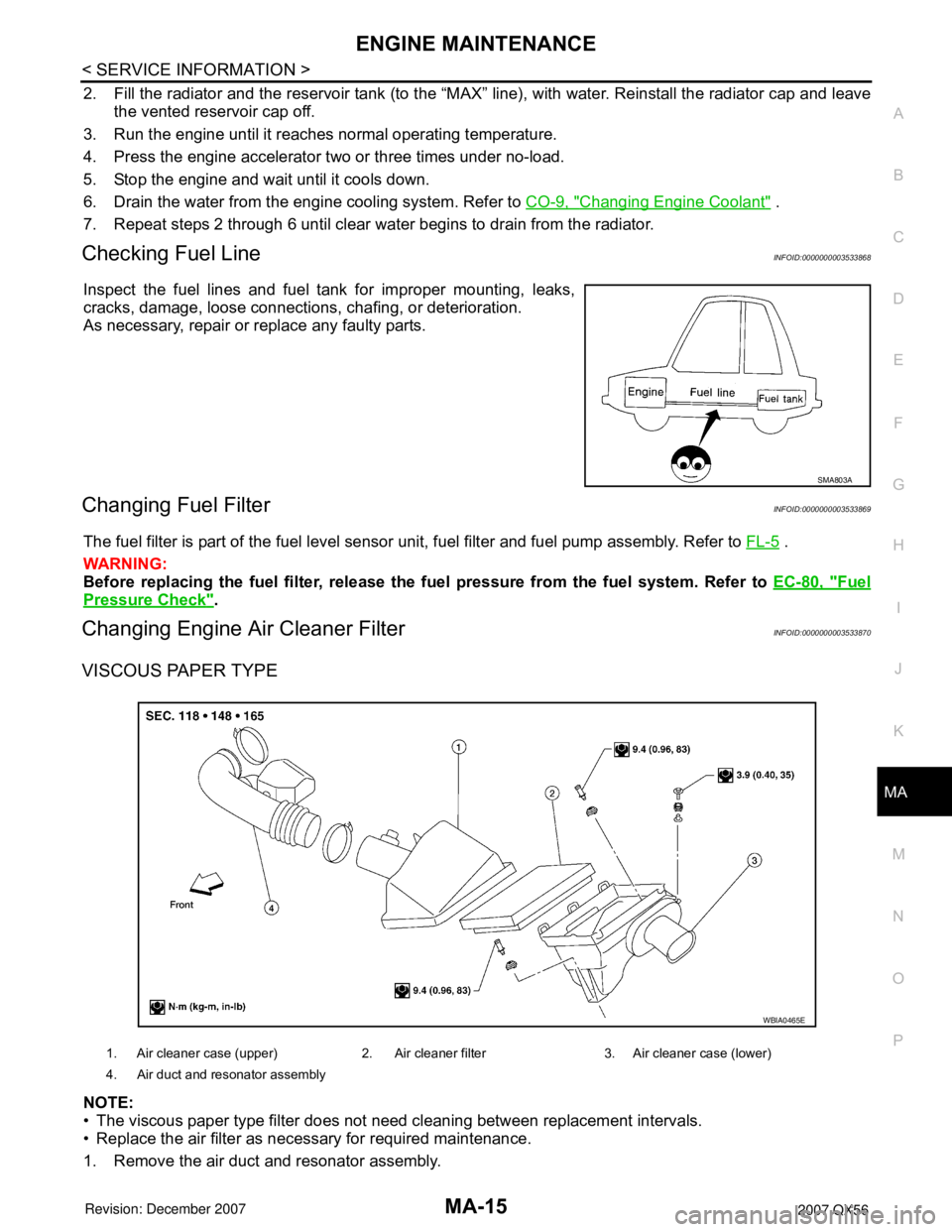
1. Remove the air duct and resonator assembly.
SMA803A
1. Air cleaner case (upper) 2. Air cleaner filter 3. Air cleaner case (lower)
4. Air duct and resonator assembly
WBIA0465E
Page 2462 of 3061

PG-60
< SERVICE INFORMATION >
HARNESS
Code Section Wiring Diagram Name
A/C,A ATC Auto Air Conditioner
A/SUSP RSU Rear Air Suspension
AF1B1 EC Air Fuel Ratio (A/F) Sensor 1 (Bank 1)
AF1B2 EC Air Fuel Ratio (A/F) Sensor 1 (Bank 2)
AF1HB1 EC Air Fuel Ratio (A/F) Sensor 1 (Bank 1)
AF1HB2 EC Air Fuel Ratio (A/F) Sensor 1 (Bank 2)
APPS1 EC Accelerator Pedal Position Sensor
APPS2 EC Accelerator Pedal Position Sensor
APPS3 EC Accelerator Pedal Position Sensor
ASC/BS EC ASCD Brake Switch
ASC/SW EC ASCD Steering Switch
ASCBOF EC ASCD Brake Switch
ASCIND EC ASCD Indicator
A/T AT A/T Assembly
AT/IND DI A/T Indicator Lamp
AUDIO AV Audio
AUT/DP SE Automatic Drive Positioner
AUTO/L LT Auto Light Control
B/CLOS BL Back Door Auto Closure System
BACK/L LT Back-up Lamp
BRK/SW EC Brake Switch
CAN EC CAN Communication Line
CAN LAN CAN System
CHARGE SC Charging System
CHIME DI Warning Chime
CLOCK DI Clock
COOL/F EC Cooling Fan Control
COMBSW LT Combination Switch
COMM AV Audio Visual Communication System
COMPAS DI Compass and Thermometer
D/LOCK BL Power Door Lock
DEF GW Rear Window Defogger
DTRL LT Headlamp - With Daytime Light System
DVD AV DVD Entertainment System
ECM/PW EC ECM Power Supply for Back-Up
ECTS EC Engine Coolant Temperature Sensor
ETC1 EC Electric Throttle Control Function
ETC2 EC Throttle Control Motor Relay
ETC3 EC Throttle Control Motor
F/FOG LT Front Fog Lamp
F/PUMP EC Fuel Pump
FTTS EC Fuel Tank Temperature Sensor
FUELB1 EC Fuel Injection System Bank 1
FUELB2 EC Fuel Injection System Bank 2
H/AIM LT Headlamp Aiming Control
H/PHON AV Hands Free Telephone
H/LAMP LT Headlamp
HORN WW Horn
HSEAT SE Heated Seat
ICC ACS Intelligent Cruise Control
ICCBOF EC ICC Brake Switch
Page 2660 of 3061
SC-12
< SERVICE INFORMATION >
STARTING SYSTEM
DIAGNOSTIC PROCEDURE 1
Check Starter Motor Circuit
1.CHECK POWER SUPPLY TO STARTER MOTOR
1. Remove the fuel pump fuse.
2. Crank or start the engine (where possible) until the fuel pressure is released.
3. Turn the ignition switch OFF.
*1SC-6, "Trouble Diagnosis with Bat-
tery/Starting/Charging System
Te s t e r"
*2 "MINIMUM SPECIFICATION OF
CRANKING VOLTAGE REFERENC-
ING COOLANT TEMPERATURE"*3 "DIAGNOSTIC PROCEDURE 1"
*4 "DIAGNOSTIC PROCEDURE 2"
WKIA4532E
Page 2662 of 3061
![INFINITI QX56 2007 Factory Service Manual SC-14
< SERVICE INFORMATION >
STARTING SYSTEM
• Starter relay [within the intelligent power distribution module engine room (IPDM E/R)]
• Harness for open or short
2.CHECK VOLTAGE DROP ON MAGNETIC INFINITI QX56 2007 Factory Service Manual SC-14
< SERVICE INFORMATION >
STARTING SYSTEM
• Starter relay [within the intelligent power distribution module engine room (IPDM E/R)]
• Harness for open or short
2.CHECK VOLTAGE DROP ON MAGNETIC](/manual-img/42/57029/w960_57029-2661.png)
SC-14
< SERVICE INFORMATION >
STARTING SYSTEM
• Starter relay [within the intelligent power distribution module engine room (IPDM E/R)]
• Harness for open or short
2.CHECK VOLTAGE DROP ON MAGNETIC SWITCH CIRCUIT
1. Turn the ignition switch OFF.
2. Connect starter motor connector F28.
3. Check voltage between starter motor connector F28 terminal 1
and battery positive terminal using a digital circuit tester.
OK or NG
OK >> Magnetic switch circuit is OK. Further inspection is nec-
essary. Refer to "WORK FLOW" .
NG >> Check harness between the battery and the magnetic
switch for poor continuity.
MINIMUM SPECIFICATION OF CRANKING VOLTAGE REFERENCING COOLANT TEMPERA-
TURE
Removal and InstallationINFOID:0000000003533322
REMOVAL
1. Remove the intake manifold. Refer to EM-17, "Removal and Installation".
2. Remove/disconnect the starter harness connectors.
3. Remove the two starter bolts, using power tools.
4. Remove the starter.
INSTALLATION
Installation is in the reverse order of removal.
CAUTION:
Tighten terminal nut carefully.Ignition switch in
START.: Less than 1V
WKIA1792E
Engine coolant temperature Voltage V
−30°C to −20°C (−22°F to −4°F) 8.4
−19°C to −10°C (−2°F to 14°F) 8.9
−9°C to 0°C (16°F to 32°F) 9.3
More than 1°C (More than 34°F) 9.7
WKIA1388E
Terminal nut : 10.8 N·m (1.1 kg-m, 8 ft-lb)