2007 INFINITI QX56 instrument panel
[x] Cancel search: instrument panelPage 2819 of 3061

COLLISION DIAGNOSIS
SRS-49
< SERVICE INFORMATION >
C
D
E
F
G
I
J
K
L
MA
B
SRS
N
O
P
COLLISION DIAGNOSIS
For Frontal CollisionINFOID:0000000003532882
Check the SRS components using the following table.
• After the work is completed, perform self-diagnosis to check that no malfunction is detected. Refer to SRS-
20, "SRS Operation Check" .
SRS INSPECTION (FOR FRONTAL COLLISION)
Part SRS is activated SRS is NOT activated
Driver air bag module If the driver air bag
has deployed:
REPLACE
Install with new fas-
teners.If the driver air bag has NOT been activated:
1. Remove driver air bag module. Check harness cover and connectors for dam-
age, terminals for deformities, and harness for binding.
2. Install driver air bag module into the steering wheel to check fit and alignment
with the wheel.
3. If no damage is found, reinstall with new fasteners.
4. If damaged—REPLACE. Install driver air bag modules with new fasteners.
Front passenger air
bag moduleIf the front passenger
air bag has deployed:
REPLACE
Install with new fas-
teners.If the front passenger air bag has NOT been activated:
1. Remove front passenger air bag module. Check harness cover and connectors
for damage, terminals for deformities, and harness for binding.
2. Install front passenger air bag module into the instrument panel to check fit with
the instrument panel.
3. If no damage is found, reinstall with new fasteners.
4. If damaged—REPLACE. Install front passenger air bag modules with new fas-
teners.
Crash zone sensor If any of the front air
bags or seat belt pre-
tensioners* have
been activated:
REPLACE the crash
zone sensor and
bracket with new fas-
teners.
*: Confirm seat belt
pre-tensioner activa-
tion using CONSULT-
II only.If the front air bags or seat belt pre-tensioners have NOT been activated:
1. Remove the crash zone sensor. Check harness connectors for damage, termi-
nals for deformities, and harness for binding.
2. Check for visible signs of damage (dents, cracks, deformation) of the crash zone
sensor and bracket.
3. Install the crash zone sensor to check fit.
4. If no damage is found, reinstall with new fasteners.
5. If damaged—REPLACE the crash zone sensor and bracket with new fasteners.
Seat belt pre-tension-
er assemblies
(All applicable loca-
tions: buckle, reel, lap
outer)If either the driver or
passenger seat belt
pre-tensioner* has
been activated:
REPLACE all seat
belt pre-tensioner as-
semblies with new
fasteners.
*: Confirm seat belt
pre-tensioner activa-
tion using CONSULT-
II only.If the pre-tensioners have NOT been activated:
1. Remove seat belt pre-tensioners.
Check harness cover and connectors for damage, terminals for deformities, and
harness for binding.
2. Check belts for damage and anchors for loose mounting.
3. Check retractor for smooth operation.
4. Check seat belt adjuster for damage.
5. Check for deformities of the center pillar inner.
6. If the center pillar inner has no damage, REPLACE the seat belt pre-tensioner
assembly.
7. If no damage is found, reinstall seat belt pre-tensioner assembly.
8. If damaged—REPLACE. Install the seat belt pre-tensioners with new fasteners.
Diagnosis sensor unit If any of the SRS com-
ponents have been
activated:
REPLACE the diag-
nosis sensor unit.
Install with new fas-
teners.If none of the SRS components have been activated:
1. Check case for dents, cracks or deformities.
2. Check connectors for damage, and terminals for deformities.
3. If no damage is found, reinstall with new fasteners.
4. If damaged—REPLACE. Install diagnosis sensor unit with new fasteners.
Page 2820 of 3061

SRS-50
< SERVICE INFORMATION >
COLLISION DIAGNOSIS
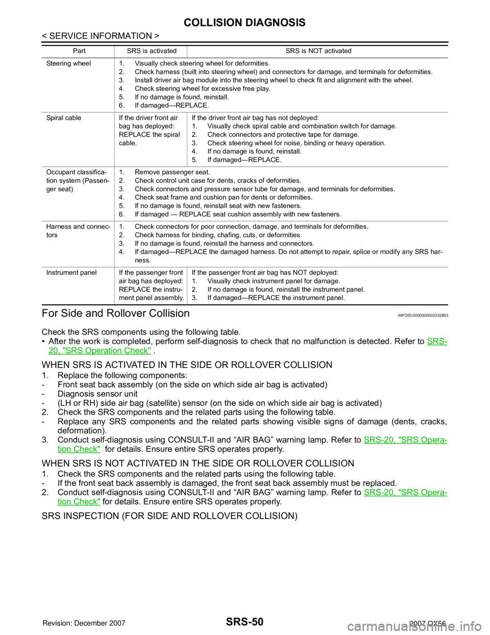
For Side and Rollover Collision
INFOID:0000000003532883
Check the SRS components using the following table.
• After the work is completed, perform self-diagnosis to check that no malfunction is detected. Refer to SRS-
20, "SRS Operation Check" .
WHEN SRS IS ACTIVATED IN THE SIDE OR ROLLOVER COLLISION
1. Replace the following components:
- Front seat back assembly (on the side on which side air bag is activated)
- Diagnosis sensor unit
- (LH or RH) side air bag (satellite) sensor (on the side on which side air bag is activated)
2. Check the SRS components and the related parts using the following table.
- Replace any SRS components and the related parts showing visible signs of damage (dents, cracks,
deformation).
3. Conduct self-diagnosis using CONSULT-II and “AIR BAG” warning lamp. Refer to SRS-20, "
SRS Opera-
tion Check" for details. Ensure entire SRS operates properly.
WHEN SRS IS NOT ACTIVATED IN THE SIDE OR ROLLOVER COLLISION
1. Check the SRS components and the related parts using the following table.
- If the front seat back assembly is damaged, the front seat back assembly must be replaced.
2. Conduct self-diagnosis using CONSULT-II and “AIR BAG” warning lamp. Refer to SRS-20, "
SRS Opera-
tion Check" for details. Ensure entire SRS operates properly.
SRS INSPECTION (FOR SIDE AND ROLLOVER COLLISION)
Steering wheel 1. Visually check steering wheel for deformities.
2. Check harness (built into steering wheel) and connectors for damage, and terminals for deformities.
3. Install driver air bag module into the steering wheel to check fit and alignment with the wheel.
4. Check steering wheel for excessive free play.
5. If no damage is found, reinstall.
6. If damaged—REPLACE.
Spiral cable If the driver front air
bag has deployed:
REPLACE the spiral
cable.If the driver front air bag has not deployed:
1. Visually check spiral cable and combination switch for damage.
2. Check connectors and protective tape for damage.
3. Check steering wheel for noise, binding or heavy operation.
4. If no damage is found, reinstall.
5. If damaged—REPLACE.
Occupant classifica-
tion system (Passen-
ger seat)1. Remove passenger seat.
2. Check control unit case for dents, cracks of deformities.
3. Check connectors and pressure sensor tube for damage, and terminals for deformities.
4. Check seat frame and cushion pan for dents or deformities.
5. If no damage is found, reinstall seat with new fasteners.
6. If damaged — REPLACE seat cushion assembly with new fasteners.
Harness and connec-
tors1. Check connectors for poor connection, damage, and terminals for deformities.
2. Check harness for binding, chafing, cuts, or deformities.
3. If no damage is found, reinstall the harness and connectors.
4. If damaged—REPLACE the damaged harness. Do not attempt to repair, splice or modify any SRS har-
ness.
Instrument panel If the passenger front
air bag has deployed:
REPLACE the instru-
ment panel assembly.If the passenger front air bag has NOT deployed:
1. Visually check instrument panel for damage.
2. If no damage is found, reinstall the instrument panel.
3. If damaged—REPLACE the instrument panel. Part SRS is activated SRS is NOT activated
Page 2997 of 3061

WT-8
< SERVICE INFORMATION >
LOW TIRE PRESSURE WARNING SYSTEM
LOW TIRE PRESSURE WARNING SYSTEM
System ComponentINFOID:0000000003532692
System DescriptionINFOID:0000000003532693
BODY CONTROL MODULE (BCM)
The BCM is shown with the lower instrument panel LH removed. The
BCM reads the air pressure signal received by the remote keyless
entry receiver, and controls the low tire pressure warning lamp as
shown below. It also has a self-diagnosis function to detect a system
malfunction.
TRANSMITTER
A sensor-transmitter integrated with a valve is installed in each
wheel, and transmits a detected air pressure signal in the form of a
radio wave. The radio signal is received by the remote keyless entry
receiver.
WEIA0081E
Condition Low tire pressure warning lamp
System normal On for 1 second after ignition ON
Tire less than 193 kPa (2.0 kg/cm
2 , 28 psi)
[Flat tire]ON
Low tire pressure warning system malfunc-
tionAfter key ON, flashes once per sec-
ond for 1 minute, then stays ON
LEIA0068E
WEIA0137E
Page 2998 of 3061

LOW TIRE PRESSURE WARNING SYSTEM
WT-9
< SERVICE INFORMATION >
C
D
F
G
H
I
J
K
L
MA
B
WT
N
O
P
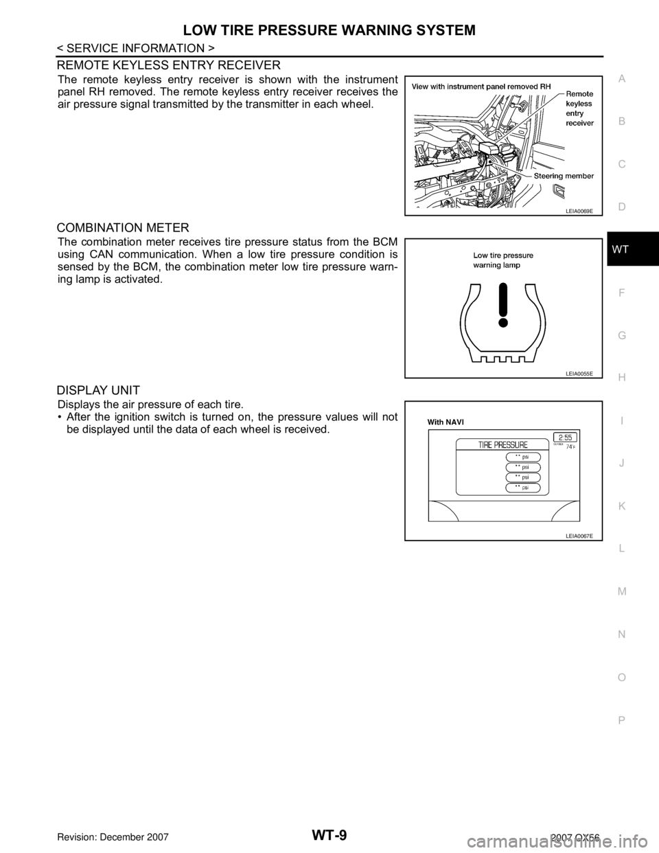
REMOTE KEYLESS ENTRY RECEIVER
The remote keyless entry receiver is shown with the instrument
panel RH removed. The remote keyless entry receiver receives the
air pressure signal transmitted by the transmitter in each wheel.
COMBINATION METER
The combination meter receives tire pressure status from the BCM
using CAN communication. When a low tire pressure condition is
sensed by the BCM, the combination meter low tire pressure warn-
ing lamp is activated.
DISPLAY UNIT
Displays the air pressure of each tire.
• After the ignition switch is turned on, the pressure values will not
be displayed until the data of each wheel is received.
LEIA0069E
LEIA0055E
LEIA0067E