2007 INFINITI QX56 instrument panel
[x] Cancel search: instrument panelPage 2034 of 3061
POWER WINDOW SYSTEM
GW-15
< SERVICE INFORMATION >
C
D
E
F
G
H
J
K
L
MA
B
GW
N
O
P
POWER WINDOW SYSTEM
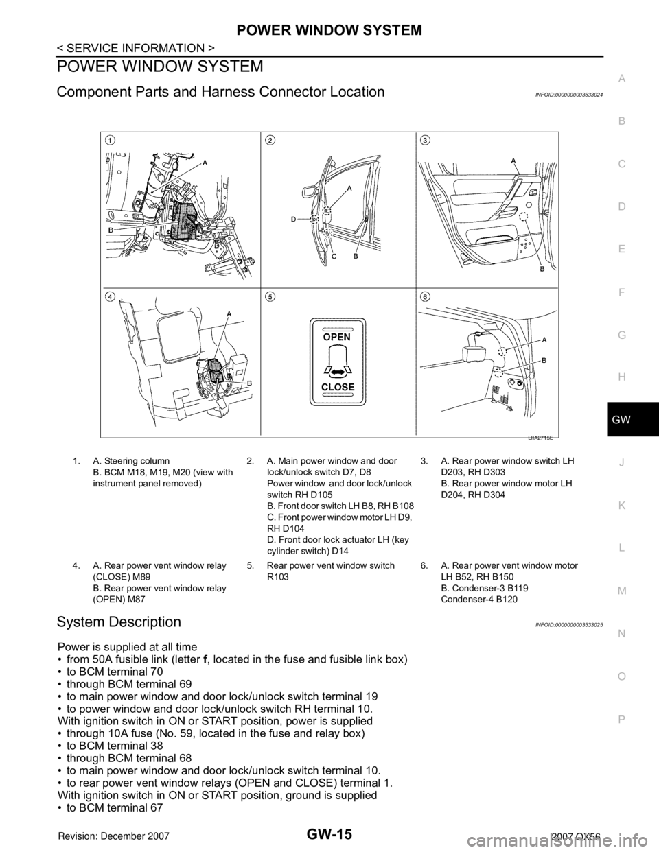
Component Parts and Harness Connector LocationINFOID:0000000003533024
System DescriptionINFOID:0000000003533025
Power is supplied at all time
• from 50A fusible link (letter f, located in the fuse and fusible link box)
• to BCM terminal 70
• through BCM terminal 69
• to main power window and door lock/unlock switch terminal 19
• to power window and door lock/unlock switch RH terminal 10.
With ignition switch in ON or START position, power is supplied
• through 10A fuse (No. 59, located in the fuse and relay box)
• to BCM terminal 38
• through BCM terminal 68
• to main power window and door lock/unlock switch terminal 10.
• to rear power vent window relays (OPEN and CLOSE) terminal 1.
With ignition switch in ON or START position, ground is supplied
• to BCM terminal 67
1. A. Steering column
B. BCM M18, M19, M20 (view with
instrument panel removed)2. A. Main power window and door
lock/unlock switch D7, D8
Power window and door lock/unlock
switch RH D105
B. Front door switch LH B8, RH B108
C. Front power window motor LH D9,
RH D104
D. Front door lock actuator LH (key
cylinder switch) D143. A. Rear power window switch LH
D203, RH D303
B. Rear power window motor LH
D204, RH D304
4. A. Rear power vent window relay
(CLOSE) M89
B. Rear power vent window relay
(OPEN) M875. Rear power vent window switch
R1036. A. Rear power vent window motor
LH B52, RH B150
B. Condenser-3 B119
Condenser-4 B120
LIIA2715E
Page 2107 of 3061
IDX-3
A
C
D
E
F
G
H
I
J
K
L B
IDX
ALPHABETICAL INDEX
Brake fluid level ................................................. MA-28
Brake hydraulic line ........................................... BR-12
Brake inspection ................................................ MA-28
Brake lines and cables inspection ..................... MA-28
Brake master cylinder ....................................... BR-15
Brake switch ...................................... EC-572, EC-584
BRK/SW - Wiring diagram ............................... EC-585
Bulb specifications ........................................... LT-148
Bumper, front ...................................................... EI-13
Bumper, rear ....................................................... EI-15
C
Cabin air filter .................................................... MA-21
Camshaft ........................................................... EM-46
Camshaft inspection .......................................... EM-49
Camshaft position sensor (PHASE) ................ EC-369
CAN - Wiring diagram .............. EC-157, AT-93, AT-94
CAN communication EC-32, EC-156, EC-159, TF-112,
RSU-6
Canister-See EVAP canister ............................. EC-36
Center case (Transfer) ....................... TF-154, TF-167
CHARGE - Wiring diagram ............................... SC-19
Charging system ............................................... SC-17
Chassis and body maintenance ........................ MA-21
Chassis and body maintenanceSchedule 1 ........ MA-8
Chassis and body maintenanceSchedule 2 ...... MA-10
CHIME - Wiring diagram ..................................... DI-41
Circuit breaker ................................................... PG-17
Clock ................................................................... DI-61
CLOCK - Wiring diagram .................................... DI-61
Closed loop control ............................. EC-26, EC-501
Closed loop control (Bank 1) ........................... EC-501
Closed loop control (Bank 2) ........................... EC-501
Clutch drum (Transfer) ....................... TF-154, TF-167
Clutch pressure switch (Transfer) ...... TF-154, TF-167
Coil spring (front) ............................................. FSU-10
Collision diagnosis .......................................... SRS-53
Combination lamp, front, removal and installation . LT-
25
Combination lamp, rear, removal and installation .. LT-
101
Combination meter ................................................ DI-5
Combination switch ............................................ LT-79
COMBSW - Wiring diagram ............................... LT-79
COMM - Wiring diagram ................................... AV-94
COMPAS - Wiring diagram ................................. DI-24
Compass ............................................................. DI-23
Component Location (auto A/C) ...................... ATC-38
Compressor clutch removal and installation . ATC-180
Compressor mounting ................................... ATC-179
Compressor precaution ................................... ATC-11
Compressor special service tool ..................... ATC-14
Condenser ..................................................... ATC-184
Connecting rod .................................................. EM-96
Connecting rod bearing clearance .................... EM-96
Connecting rod bushing clearance .................... EM-96
Console box - See Instrument panel ................... IP-10
CONSULT for VDC ......................................... BRC-27
CONSULT general information ........................... GI-37
CONSULT-II for engine ................................... EC-118
Control units (terminal arrangement) ................. PG-71
Control valve (A/T) ............................................. AT-36
Control valve (Transfer) ...................... TF-154, TF-167
Converter housing installation ............ AT-240, AT-244
COOL/F - Wiring diagram ................................ EC-507
Coolant mixture ratio ......................................... MA-12
Coolant replacement ............................ CO-10, MA-13
Cooling circuit (engine) ........................................ CO-8
Cooling fan ........................................................ CO-17
Cooling fan control ........................................... EC-504
Cooling fan motor ............................................ EC-513
Cooling unit (A/C evaporator) ....... ATC-157, ATC-186
Corrosion protection ......................................... BL-157
Crankcase ventilation system - See Positive crankcase
ventilation .......................................................... EC-46
Crankshaft ......................................................... EM-79
Crankshaft position sensor (POS) ................... EC-362
Crash zone sensor .......................................... SRS-48
CUR/SE - Wiring diagram ... EC-522, EC-529, EC-536,
EC-543
Cylinder block .................................................... EM-78
Cylinder block boring ......................................... EM-99
D
D/LOCK - Wiring diagram ................................... BL-19
Data link connector for Consult ......... EC-120, EC-132
Daytime light system .......................................... LT-27
Daytime running light - See Daytime light system .. LT-
27
DEF - Wiring diagram ....................................... GW-74
Diagnosis sensor unit ...................................... SRS-51
Diagnostic trouble code (DTC) for OBD system . EC-9,
EC-54
Diagnostic trouble code (DTC) inspection priority chart
EC-91
Differential carrier assembly ............................ RFD-15
Differential gear oil replacement ........................ MA-26
Dimensions ......................................................... GI-51
Direct clutch solenoid valve ................ AT-143, AT-145
Display and amp.assembly .............................. ATC-59
Display Control Unit ........................................... AV-83
Display Unit ....................................................... AV-83
Dome light - See Interior lamp .......................... LT-110
Door glass .......................................... GW-62, GW-65
Door lock .......................................................... BL-121
Door mirror lamp ............................................... LT-110
Door trim .............................................................. EI-32
Door, front ........................................... BL-117, GW-62
Door, rear ........................................... BL-117, GW-65
Drive belt ........................................................... EM-13
Drive chain (Transfer) ......................... TF-149, TF-176
Drive pinion diff. inspection .............................. RFD-18
Drive shaft (rear) ................................................ RAX-7
Driver air bag ................................................... SRS-39
DTC work support ............................................ EC-128
DTRL - Wiring diagram ....................................... LT-31
Page 2109 of 3061
IDX-5
A
C
D
E
F
G
H
I
J
K
L B
IDX
ALPHABETICAL INDEX
Grease .............................................................. MA-11
Ground distribution ............................................ PG-31
H
H/AIM - Wiring diagram ...................................... LT-51
H/LAMP - Wiring diagram .................................... LT-9
Handling precautions for plastics ..................... BL-179
Harness connector ............................................ PG-68
Harness layout .................................................. PG-41
Hazard warning lamp ......................................... LT-63
Headlamp ............................................................. LT-5
Headlamp aiming control ................................... LT-51
Headlamp leveler - See Headlamp aiming control . LT-
51
Headlamp removal and installation .................... LT-25
Heated oxygen sensor 2 (bank 1) .... EC-276, EC-287,
EC-300
Heated oxygen sensor 2 (bank 2) .... EC-276, EC-287,
EC-300
Heated oxygen sensor 2 heater (bank 1) ........ EC-181
Heated oxygen sensor 2 heater (bank 2) ........ EC-181
Heated seat ....................................................... SE-82
Heater and cooling unit (Heater core) . ATC-157, ATC-
160
Heater unit (heater core) ............... ATC-157, ATC-160
Height (Dimensions) ........................................... GI-51
HFC134a (R134a) system identification ........... ATC-6
HFC134a (R134a) system precaution ............... ATC-5
HFC134a (R134a) system service procedure ATC-175
HFC134a (R134a) system service tools ......... ATC-14
HFC134a system service equipment precaution ATC-
11
High and low reverse clutch solenoid valve .... AT-147,
AT-149
Homelink universal transceiver ........................ BL-146
Horn ................................................................ WW-48
HORN - Wiring diagram .................................. WW-48
How to erase DTC for OBD system .................. EC-63
HSEAT - Wiring diagram ................................... SE-84
I
IATS - Wiring diagram ..................................... EC-215
ICC - Wiring diagram ....................................... ACS-20
ICC/BS - Wiring diagram ................................. EC-565
ICC/SW - Wiring diagram ................................ EC-550
ICCBOF - Wiring diagram ............................... EC-672
Identification plate .............................................. GI-49
Idle air volume learning ..................................... EC-80
Idle speed .............................................. EC-73, EC-78
Idle speed control (ISC) .................... EC-466, EC-468
Ignition coil .......................................... EM-28, EC-679
Ignition control system .................................... EC-679
Ignition key hole illumination ............................ LT-110
Ignition timing ........................................ EC-73, EC-78
IGNSYS - Wiring diagram ............................... EC-680
ILL - Wiring diagram ......................................... LT-136
Illumination ....................................................... LT-130
In vehicle sensor ........................... ATC-141, ATC-150
In-cabin Microfilter ............................................. MA-21
INJECT - Wiring diagram ................................. EC-660
Injector ............................................................. EC-659
Input clutch solenoid valve ................. AT-135, AT-137
Instrument panel .................................................. IP-10
Intake air temperature sensor ............ EC-214, EC-234
Intake door control linkage adjustment . ATC-85, ATC-
88
Intake door motor ........................... ATC-83, ATC-164
Intake manifold .................................................. EM-17
Intake sensor ................................ ATC-146, ATC-152
Intake valve timing control (Bank 1) ................ EC-161
Intake valve timing control (Bank 2) ................ EC-161
Intake valve timing control position sensor (Bank 1) ....
EC-492
Intake valve timing control position sensor (Bank 2) ....
EC-492
Intake valve timing control solenoid valve (Bank 1) EC-
189
Intake valve timing control solenoid valve (Bank 2) EC-
189
Integrated homelink transmitter - See Homelink univer-
sal tranceiver .................................................... BL-146
Intelligent cruise control (ICC) system ............... ACS-6
Interior ................................................................. EI-35
Interior lamp ...................................................... LT-110
Interior lamp on-off control ................................ LT-111
Internal gear (Transfer) ....................... TF-149, TF-176
IPDM (Intelligent power distribution module engine
room) ................................................................. PG-18
IVCB1 - Wiring diagram ................................... EC-190
IVCB2 - Wiring diagram ................................... EC-192
IVCSB1 - Wiring diagram ................................ EC-493
IVCSB2 - Wiring diagram ................................ EC-495
IVIS (Infiniti vehicle immobilizer system) .......... BL-127
IVIS (Infiniti vehicle immobilizer system) precautions ...
GI-3
IVTB1 - Wiring diagram ................................... EC-164
IVTB2 - Wiring diagram ................................... EC-166
J
Jacking points ..................................................... GI-42
Junction box (J/B) .............................................. PG-76
K
Key illumination ................................................ LT-111
KEYLES - Wiring diagram .................................. BL-45
Knock sensor (KS) ........................................... EC-357
KS - Wiring diagram ........................................ EC-358
L
Laser beam aiming adjustment ....................... ACS-12
Length (Dimensions) .......................................... GI-51
License lamp ...................................................... LT-89
Lifting points ....................................................... GI-43
Page 2113 of 3061

IP-1
BODY
C
D
E
F
G
H
J
K
L
M
SECTION IP
A
B
IP
N
O
P
CONTENTS
INSTRUMENT PANEL
SERVICE INFORMATION ............................2
PRECAUTIONS ...................................................2
Precaution for Supplemental Restraint System
(SRS) "AIR BAG" and "SEAT BELT PRE-TEN-
SIONER" ...................................................................
2
PREPARATION ...................................................3
Special Service Tool .................................................3
Commercial Service Tool ..........................................3
SQUEAK AND RATTLE TROUBLE DIAGNO-
SIS ......................................................................
4
Work Flow .................................................................4
Generic Squeak and Rattle Troubleshooting ............6
Diagnostic Worksheet ...............................................8
INSTRUMENT PANEL ASSEMBLY .................10
Removal and Installation .........................................10
Disassembly and Assembly .....................................14
Page 2117 of 3061
SQUEAK AND RATTLE TROUBLE DIAGNOSIS
IP-5
< SERVICE INFORMATION >
C
D
E
F
G
H
J
K
L
MA
B
IP
N
O
P
If the noise can be duplicated easily during the test drive, to help identify the source of the noise, try to dupli-
cate the noise with the vehicle stopped by doing one or all of the following:
1. Close a door.
2. Tap or push/pull around the area where the noise appears to be coming from.
3. Rev the engine.
4. Use a floor jack to recreate vehicle “twist”.
5. At idle, apply engine load (electrical load, drive position on A/T model).
6. Raise the vehicle on a hoist and hit a tire with a rubber hammer.
• Drive the vehicle and attempt to duplicate the conditions the customer states exist when the noise occurs.
• If it is difficult to duplicate the noise, drive the vehicle slowly on an undulating or rough road to stress the
vehicle body.
CHECK RELATED SERVICE BULLETINS
After verifying the customer concern or symptom, check ASIST for Technical Service Bulletins (TSBs) related
to that concern or symptom.
If a TSB relates to the symptom, follow the procedure to repair the noise.
LOCATE THE NOISE AND IDENTIFY THE ROOT CAUSE
1. Narrow down the noise to a general area. To help pinpoint the source of the noise, use a listening tool
(Chassis Ear: J-39570, Engine Ear: J-39565 and mechanics stethoscope).
2. Narrow down the noise to a more specific area and identify the cause of the noise by:
• Removing the components in the area that you suspect the noise is coming from.
Do not use too much force when removing clips and fasteners, otherwise clips and fasteners
can be broken or lost during the repair, resulting in the creation of new noise.
• Tapping or pushing/pulling the component that you suspect is causing the noise.
Do not tap or push/pull the component with excessive force, otherwise the noise will be elimi-
nated only temporarily.
• Feeling for a vibration with your hand by touching the component(s) that you suspect is (are) causing
the noise.
• Placing a piece of paper between components that you suspect are causing the noise.
• Looking for loose components and contact marks.
Refer to IP-6, "
Generic Squeak and Rattle Troubleshooting".
REPAIR THE CAUSE
• If the cause is a loose component, tighten the component securely.
• If the cause is insufficient clearance between components:
- Separate components by repositioning or loosening and retightening the component, if possible.
- Insulate components with a suitable insulator such as urethane pads, foam blocks, felt cloth tape or ure-
thane tape. A NISSAN Squeak and Rattle Kit (J-43980) is available through your authorized NISSAN Parts
Department.
CAUTION:
Do not use excessive force as many components are constructed of plastic and may be damaged.
Always check with the Parts Department for the latest parts information.
The following materials are contained in the NISSAN Squeak and Rattle Kit (J-43980). Each item can be
ordered separately as needed.
URETHANE PADS [1.5 mm (0.059 in) thick]
Insulates connectors, harness, etc.
76268-9E005: 100 x 135 mm (3.94 x 5.31 in)/76884-71L01: 60 x 85 mm (2.36 x 3.35 in)/76884-71L02: 15 x 25
mm (0.59 x 0.98 in)
INSULATOR (Foam blocks)
Insulates components from contact. Can be used to fill space behind a panel.
73982-9E000: 45 mm (1.77 in) thick, 50 x 50 mm (1.97 x 1.97 in)/73982-50Y00: 10 mm (0.39 in) thick, 50 x 50
mm (1.97 x 1.97 in)
INSULATOR (Light foam block)
80845-71L00: 30 mm (1.18 in) thick, 30 x 50 mm (1.18 x 1.97 in)
FELT CLOTH TAPE
Used to insulate where movement does not occur. Ideal for instrument panel applications.
68370-4B000: 15 x 25 mm (0.59 x 0.98 in) pad/68239-13E00: 5 mm (0.20 in) wide tape roll
The following materials, not found in the kit, can also be used to repair squeaks and rattles.
UHMW (TEFLON) TAPE
Insulates where slight movement is present. Ideal for instrument panel applications.
Page 2118 of 3061
IP-6
< SERVICE INFORMATION >
SQUEAK AND RATTLE TROUBLE DIAGNOSIS
SILICONE GREASE
Used in place of UHMW tape that will be visible or not fit.
Note: Will only last a few months.
SILICONE SPRAY
Use when grease cannot be applied.
DUCT TAPE
Use to eliminate movement.
CONFIRM THE REPAIR
Confirm that the cause of a noise is repaired by test driving the vehicle. Operate the vehicle under the same
conditions as when the noise originally occurred. Refer to the notes on the Diagnostic Worksheet.
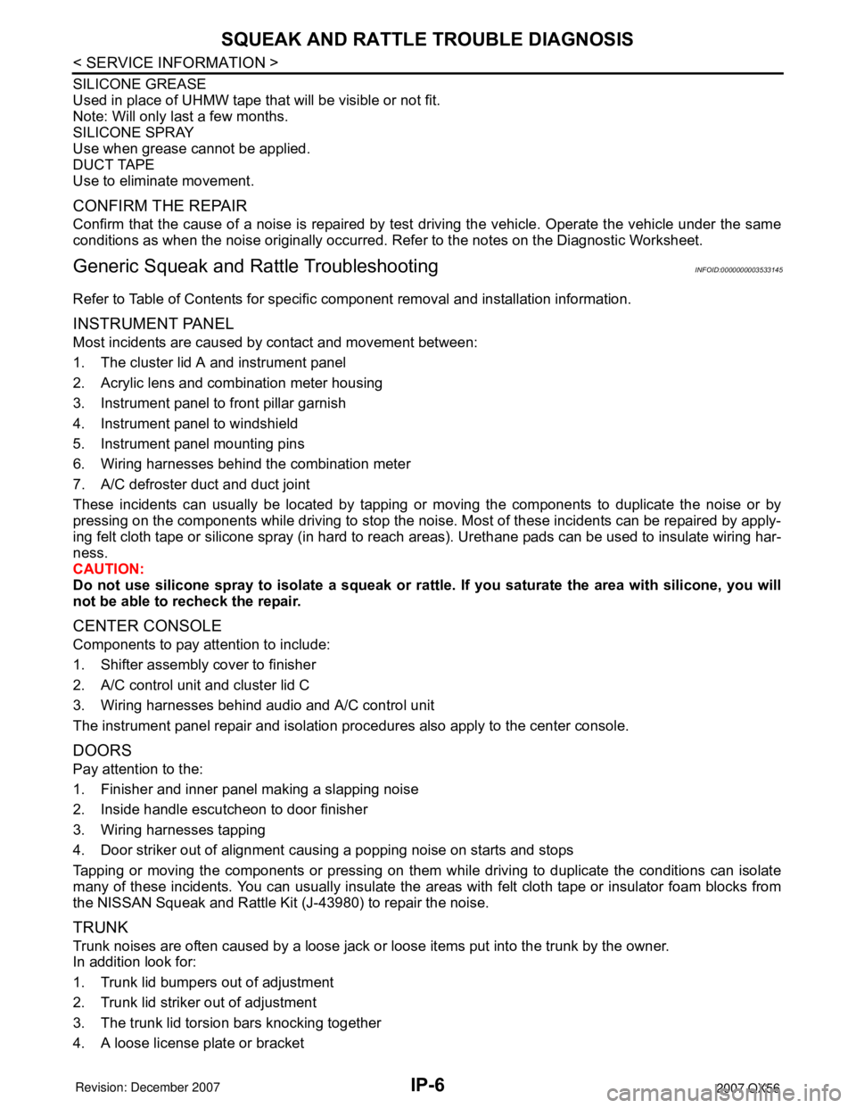
Generic Squeak and Rattle TroubleshootingINFOID:0000000003533145
Refer to Table of Contents for specific component removal and installation information.
INSTRUMENT PANEL
Most incidents are caused by contact and movement between:
1. The cluster lid A and instrument panel
2. Acrylic lens and combination meter housing
3. Instrument panel to front pillar garnish
4. Instrument panel to windshield
5. Instrument panel mounting pins
6. Wiring harnesses behind the combination meter
7. A/C defroster duct and duct joint
These incidents can usually be located by tapping or moving the components to duplicate the noise or by
pressing on the components while driving to stop the noise. Most of these incidents can be repaired by apply-
ing felt cloth tape or silicone spray (in hard to reach areas). Urethane pads can be used to insulate wiring har-
ness.
CAUTION:
Do not use silicone spray to isolate a squeak or rattle. If you saturate the area with silicone, you will
not be able to recheck the repair.
CENTER CONSOLE
Components to pay attention to include:
1. Shifter assembly cover to finisher
2. A/C control unit and cluster lid C
3. Wiring harnesses behind audio and A/C control unit
The instrument panel repair and isolation procedures also apply to the center console.
DOORS
Pay attention to the:
1. Finisher and inner panel making a slapping noise
2. Inside handle escutcheon to door finisher
3. Wiring harnesses tapping
4. Door striker out of alignment causing a popping noise on starts and stops
Tapping or moving the components or pressing on them while driving to duplicate the conditions can isolate
many of these incidents. You can usually insulate the areas with felt cloth tape or insulator foam blocks from
the NISSAN Squeak and Rattle Kit (J-43980) to repair the noise.
TRUNK
Trunk noises are often caused by a loose jack or loose items put into the trunk by the owner.
In addition look for:
1. Trunk lid bumpers out of adjustment
2. Trunk lid striker out of adjustment
3. The trunk lid torsion bars knocking together
4. A loose license plate or bracket
Page 2122 of 3061
IP-10
< SERVICE INFORMATION >
INSTRUMENT PANEL ASSEMBLY
INSTRUMENT PANEL ASSEMBLY
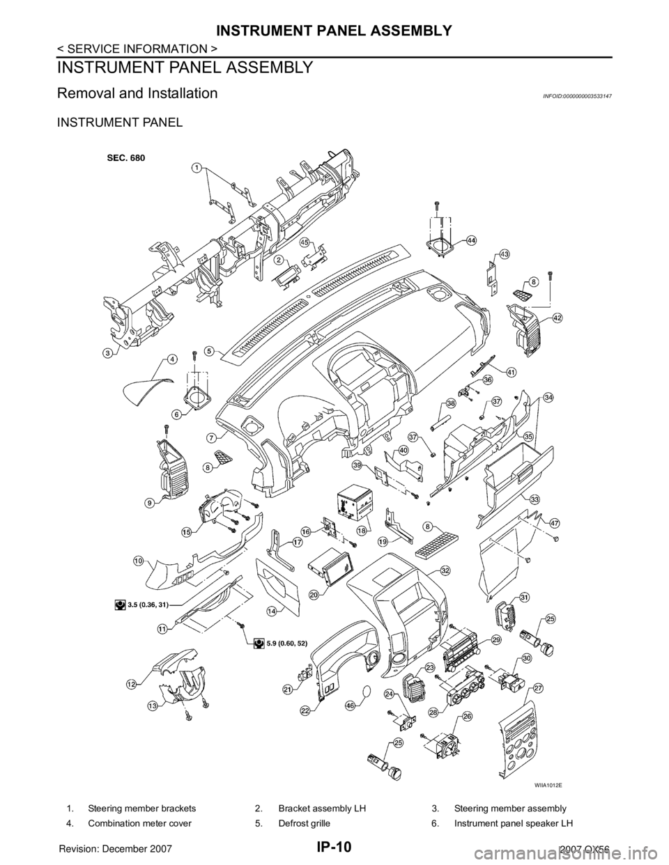
Removal and InstallationINFOID:0000000003533147
INSTRUMENT PANEL
1. Steering member brackets 2. Bracket assembly LH 3. Steering member assembly
4. Combination meter cover 5. Defrost grille 6. Instrument panel speaker LH
WIIA1012E
Page 2123 of 3061
INSTRUMENT PANEL ASSEMBLY
IP-11
< SERVICE INFORMATION >
C
D
E
F
G
H
J
K
L
MA
B
IP
N
O
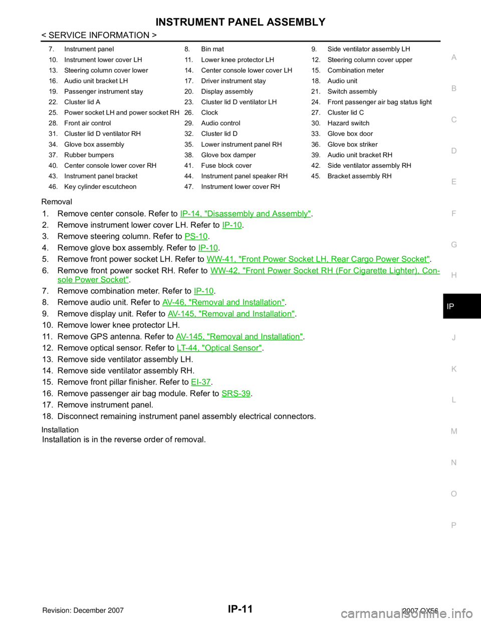
P Removal
1. Remove center console. Refer to IP-14, "Disassembly and Assembly".
2. Remove instrument lower cover LH. Refer to IP-10
.
3. Remove steering column. Refer to PS-10
.
4. Remove glove box assembly. Refer to IP-10
.
5. Remove front power socket LH. Refer to WW-41, "
Front Power Socket LH, Rear Cargo Power Socket".
6. Remove front power socket RH. Refer to WW-42, "
Front Power Socket RH (For Cigarette Lighter), Con-
sole Power Socket".
7. Remove combination meter. Refer to IP-10
.
8. Remove audio unit. Refer to AV-46, "
Removal and Installation".
9. Remove display unit. Refer to AV-145, "
Removal and Installation".
10. Remove lower knee protector LH.
11. Remove GPS antenna. Refer to AV-145, "
Removal and Installation".
12. Remove optical sensor. Refer to LT-44, "
Optical Sensor".
13. Remove side ventilator assembly LH.
14. Remove side ventilator assembly RH.
15. Remove front pillar finisher. Refer to EI-37
.
16. Remove passenger air bag module. Refer to SRS-39
.
17. Remove instrument panel.
18. Disconnect remaining instrument panel assembly electrical connectors.
Installation
Installation is in the reverse order of removal.
7. Instrument panel 8. Bin mat 9. Side ventilator assembly LH
10. Instrument lower cover LH 11. Lower knee protector LH 12. Steering column cover upper
13. Steering column cover lower 14. Center console lower cover LH 15. Combination meter
16. Audio unit bracket LH 17. Driver instrument stay 18. Audio unit
19. Passenger instrument stay 20. Display assembly 21. Switch assembly
22. Cluster lid A 23. Cluster lid D ventilator LH 24. Front passenger air bag status light
25. Power socket LH and power socket RH 26. Clock 27. Cluster lid C
28. Front air control 29. Audio control 30. Hazard switch
31. Cluster lid D ventilator RH 32. Cluster lid D 33. Glove box door
34. Glove box assembly 35. Lower instrument panel RH 36. Glove box striker
37. Rubber bumpers 38. Glove box damper 39. Audio unit bracket RH
40. Center console lower cover RH 41. Fuse block cover 42. Side ventilator assembly RH
43. Instrument panel bracket 44. Instrument panel speaker RH 45. Bracket assembly RH
46. Key cylinder escutcheon 47. Instrument lower cover RH