2007 INFINITI QX56 4WD
[x] Cancel search: 4WDPage 2506 of 3061
POWER STEERING GEAR AND LINKAGE
PS-15
< SERVICE INFORMATION >
C
D
E
F
H
I
J
K
L
MA
B
PS
N
O
P
POWER STEERING GEAR AND LINKAGE
Removal and InstallationINFOID:0000000003532829
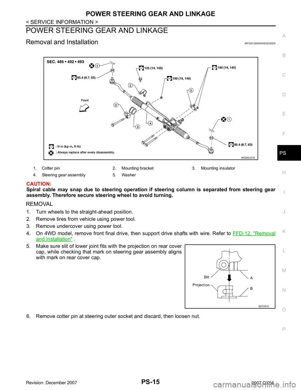
CAUTION:
Spiral cable may snap due to steering operation if steering column is separated from steering gear
assembly. Therefore secure steering wheel to avoid turning.
REMOVAL
1. Turn wheels to the straight-ahead position.
2. Remove tires from vehicle using power tool.
3. Remove undercover using power tool.
4. On 4WD model, remove front final drive, then support drive shafts with wire. Refer to FFD-12, "
Removal
and Installation" .
5. Make sure slit of lower joint fits with the projection on rear cover
cap, while checking that mark on steering gear assembly aligns
with mark on rear cover cap.
6. Remove cotter pin at steering outer socket and discard, then loosen nut.
1. Cotter pin 2. Mounting bracket 3. Mounting insulator
4. Steering gear assembly 5. Washer
WGIA0127E
SST491C
Page 2589 of 3061

RFD-32
< SERVICE INFORMATION >
SERVICE DATA AND SPECIFICATIONS (SDS)
SERVICE DATA AND SPECIFICATIONS (SDS)
General SpecificationINFOID:0000000003532608
Inspection and AdjustmentINFOID:0000000003532609
DRIVE GEAR RUNOUT
Unit: mm (in)
SIDE GEAR CLEARANCE
Unit: mm (in)
PRELOAD TORQUE
Unit: N·m (kg-m, in-lb)
BACKLASH
Unit: mm (in)
COMPANION FLANGE RUNOUT
Unit: mm (in)
SELECTIVE PARTS
Side Gear Thrust Washer
Applied modelVK56DE
2WD 4WD
Final drive modelR230
Gear ratio 2.937 3.357
Number of teeth (Drive gear/Drive pinion) 47 / 16 47 / 14
Oil capacity (Approx.)
1.75 (3 3/4 US pt, 3 1/8 Imp pt)
Number of pinion gears 2
Drive pinion adjustment spacer type Collapsible
Item Runout limit
Drive gear back face0.05 (0.0020) or less
Item Specification
Side gear back clearance
(Clearance limit between side gear and differential case for adjusting
side gear backlash)0.20 (0.0079) or less
(Each gear should rotate smoothly without excessive resis-
tance during differential motion.)
Item Specification
Drive pinion bearing preload torque 1.77 − 2.64 N·m (0.18 − 0.26 kg−m, 16 − 23 in-lb)
Side bearing preload torque (reference value determined by drive
gear bolt pulling force)0.20 − 0.52 N·m (0.02 − 0.05 kg−m, 2 − 4 in-lb)
Drive gear bolt pulling force (by spring gauge) 34.2 − 39.2 N (3.5 − 4 kg, 7.7 − 8.8 lb)
Total preload torque
(Total preload torque = drive pinion bearing preload torque + Side
bearing preload torque)2.05 − 4.11 N·m (0.21 − 0.42 kg−m, 19 − 36 in-lb)
Item Specification
Drive gear to drive pinion gear 0.13 − 0.18 (0.0051 − 0.0070)
Item Runout limit
Outer side of the companion flange 0.08 (0.0031) or less
Page 2634 of 3061
RSU-44
< SERVICE INFORMATION >
SERVICE DATA AND SPECIFICATIONS (SDS)
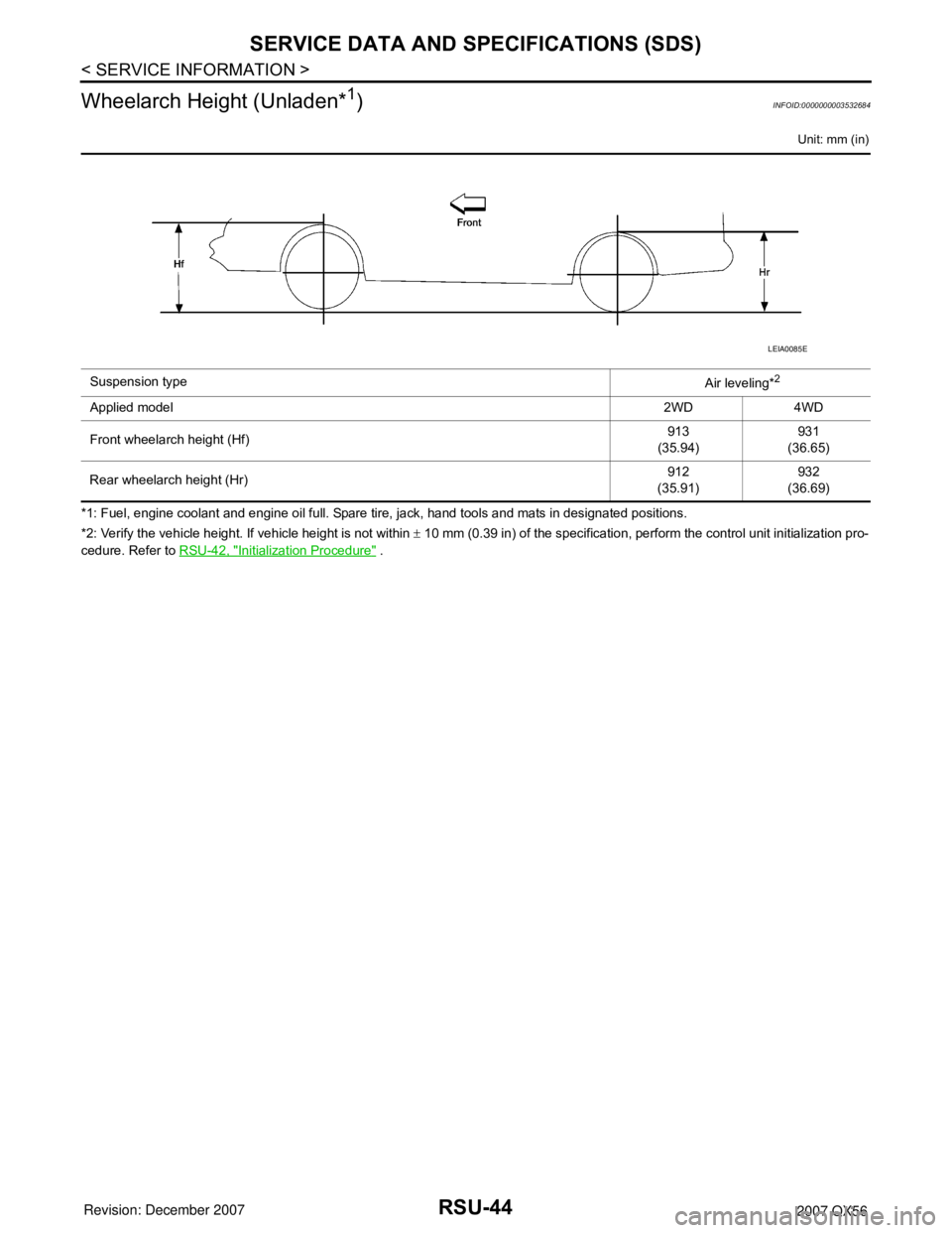
Wheelarch Height (Unladen*
1)INFOID:0000000003532684
Unit: mm (in)
*1: Fuel, engine coolant and engine oil full. Spare tire, jack, hand tools and mats in designated positions.
*2: Verify the vehicle height. If vehicle height is not within ± 10 mm (0.39 in) of the specification, perform the control unit initialization pro-
cedure. Refer to RSU-42, "
Initialization Procedure" . Suspension type
Air leveling*
2
Applied model2WD 4WD
Front wheelarch height (Hf)913
(35.94)931
(36.65)
Rear wheelarch height (Hr)912
(35.91)932
(36.69)
LEIA0085E
Page 2823 of 3061

TF-1
DRIVELINE/AXLE
C
E
F
G
H
I
J
K
L
M
SECTION TF
A
B
TF
N
O
P
CONTENTS
TRANSFER
SERVICE INFORMATION ............................3
PRECAUTIONS ...................................................3
Precaution for Supplemental Restraint System
(SRS) "AIR BAG" and "SEAT BELT PRE-TEN-
SIONER" ...................................................................
3
Precaution for Transfer Assembly and Transfer
Control Unit Replacement .........................................
3
Precaution .................................................................4
Service Notice ...........................................................4
PREPARATION ...................................................6
Special Service Tool .................................................6
Commercial Service Tool ..........................................9
NOISE, VIBRATION AND HARSHNESS
(NVH) TROUBLESHOOTING ............................
10
NVH Troubleshooting Chart ....................................10
TRANSFER FLUID .............................................11
Replacement ...........................................................11
Inspection ................................................................11
ALL-MODE 4WD SYSTEM ................................12
Cross-Sectional View ..............................................12
Power Transfer ........................................................12
System Description .................................................14
Schematic ...............................................................19
CAN Communication ...............................................20
TROUBLE DIAGNOSIS .....................................21
How to Perform Trouble Diagnosis .........................21
Location of Electrical Parts ......................................22
Circuit Diagram .......................................................23
Wiring Diagram - T/F - .............................................24
Inspections Before Trouble Diagnosis ....................31
Trouble Diagnosis Chart by Symptom ....................34
Transfer Control Unit Input/Output Signal Refer-
ence Value ..............................................................
35
CONSULT-II Function (ALL MODE AWD/4WD) .....42
Self-Diagnosis Procedure .......................................48
TROUBLE DIAGNOSIS FOR SYSTEM ............51
Power Supply Circuit for Transfer Control Unit ........51
Transfer Control Unit ...............................................53
Output Shaft Revolution Signal (TCM) ....................53
Vehicle Speed Sensor (ABS) ..................................54
Neutral-4LO Switch .................................................54
4WD Shift Switch .....................................................57
Wait Detection Switch ..............................................60
PNP Switch Signal (TCM) .......................................63
Actuator Motor .........................................................64
Actuator Position Switch ..........................................69
Transfer Control Device ...........................................72
Engine Speed Signal (ECM) ....................................76
Clutch Pressure Solenoid ........................................76
2-4WD Solenoid ......................................................80
Transfer Motor .........................................................84
Transfer Fluid Temperature .....................................90
Clutch Pressure Switch ...........................................92
Line Pressure Switch ...............................................94
Throttle Position Signal (ECM) ................................97
ABS Operation Signal (ABS) ...................................97
VDC Operation Signal (ABS) ...................................98
TCS Operation Signal (ABS) ...................................98
CAN Communication Line .......................................99
ATP Switch ..............................................................99
TROUBLE DIAGNOSIS FOR SYMPTOMS ....102
4WD Shift Indicator Lamp and 4LO Indicator
Lamp Do Not Turn ON ...........................................
102
4WD Warning Lamp Does Not Turn ON ...............104
4WD Shift Indicator Lamp or 4LO Indicator Lamp
Does Not Change ..................................................
107
ATP Warning Lamp Turns ON ...............................109
4LO Indicator Lamp Repeats Flashing ..................110
4WD Warning Lamp Flashes Rapidly ....................111
4WD Warning Lamp Flashes Slowly .....................112
Heavy Tight-corner Braking Symptom Occurs ......113
4WD System Does Not Operate ............................114
TRANSFER CONTROL UNIT .........................115
Removal and Installation .......................................115
Page 2825 of 3061
PRECAUTIONS
TF-3
< SERVICE INFORMATION >
C
E
F
G
H
I
J
K
L
MA
B
TF
N
O
P
SERVICE INFORMATION
PRECAUTIONS
Precaution for Supplemental Restraint System (SRS) "AIR BAG" and "SEAT BELT
PRE-TENSIONER"
INFOID:0000000003532506
The Supplemental Restraint System such as “AIR BAG” and “SEAT BELT PRE-TENSIONER”, used along
with a front seat belt, helps to reduce the risk or severity of injury to the driver and front passenger for certain
types of collision. This system includes seat belt switch inputs and dual stage front air bag modules. The SRS
system uses the seat belt switches to determine the front air bag deployment, and may only deploy one front
air bag, depending on the severity of a collision and whether the front occupants are belted or unbelted.
Information necessary to service the system safely is included in the SRS and SB section of this Service Man-
ual.
WARNING:
• To avoid rendering the SRS inoperative, which could increase the risk of personal injury or death in
the event of a collision which would result in air bag inflation, all maintenance must be performed by
an authorized NISSAN/INFINITI dealer.
• Improper maintenance, including incorrect removal and installation of the SRS, can lead to personal
injury caused by unintentional activation of the system. For removal of Spiral Cable and Air Bag
Module, see the SRS section.
• Do not use electrical test equipment on any circuit related to the SRS unless instructed to in this
Service Manual. SRS wiring harnesses can be identified by yellow and/or orange harnesses or har-
ness connectors.
Precaution for Transfer Assembly and Transfer Control Unit ReplacementINFOID:0000000003532507
When replacing transfer assembly or transfer control unit, check the 4WD shift indicator lamp as follows.
1. Turn ignition switch “ON”.
2. Check 4WD shift indicator lamp is turned ON for approx. 1 second.
• If OK, the position between transfer assembly and transfer control unit is correct.
• If NG, the position is different between transfer assembly and transfer control unit.
Adjust the position between transfer assembly and transfer control unit. Refer to "METHOD FOR POSITION
ADJUSTMENT".
METHOD FOR POSITION ADJUSTMENT
1. Start engine. Run the engine for at least 10 seconds.
2. Stop vehicle and move A/T selector lever to “N” position with brake pedal depressed. Stay in "N" for at
least 2 seconds.
3. Turn 4WD shift switch to “2WD” position. Stay in "2WD" for at least 2 seconds.
4. Turn ignition switch “OFF”.
5. Start engine.
6. Erase self-diagnosis. Refer to TF-42, "
CONSULT-II Function (ALL MODE AWD/4WD)" (with CONSULT-II)
or TF-48, "
Self-Diagnosis Procedure" (without CONSULT-II).
7. Check 4WD shift indicator lamp. Refer to TF-31, "
Inspections Before Trouble Diagnosis".
If 4WD shift indicator lamp does not indicate "2WD", install new transfer control unit and retry the above
check.
Page 2834 of 3061
TF-12
< SERVICE INFORMATION >
ALL-MODE 4WD SYSTEM
ALL-MODE 4WD SYSTEM
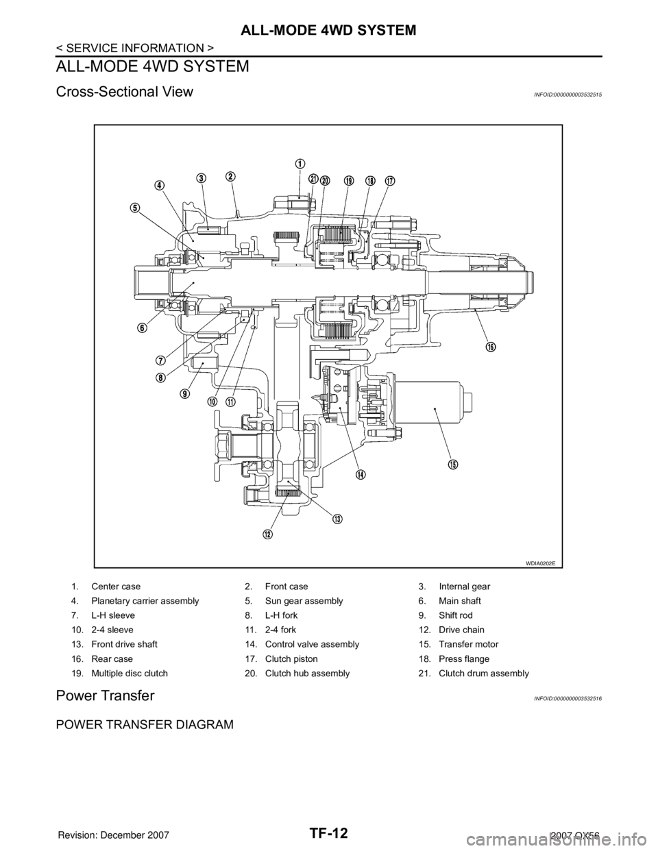
Cross-Sectional ViewINFOID:0000000003532515
Power TransferINFOID:0000000003532516
POWER TRANSFER DIAGRAM
1. Center case 2. Front case 3. Internal gear
4. Planetary carrier assembly 5. Sun gear assembly 6. Main shaft
7. L-H sleeve 8. L-H fork 9. Shift rod
10. 2-4 sleeve 11. 2-4 fork 12. Drive chain
13. Front drive shaft 14. Control valve assembly 15. Transfer motor
16. Rear case 17. Clutch piston 18. Press flange
19. Multiple disc clutch 20. Clutch hub assembly 21. Clutch drum assembly
WDIA0202E
Page 2835 of 3061
ALL-MODE 4WD SYSTEM
TF-13
< SERVICE INFORMATION >
C
E
F
G
H
I
J
K
L
MA
B
TF
N
O
P
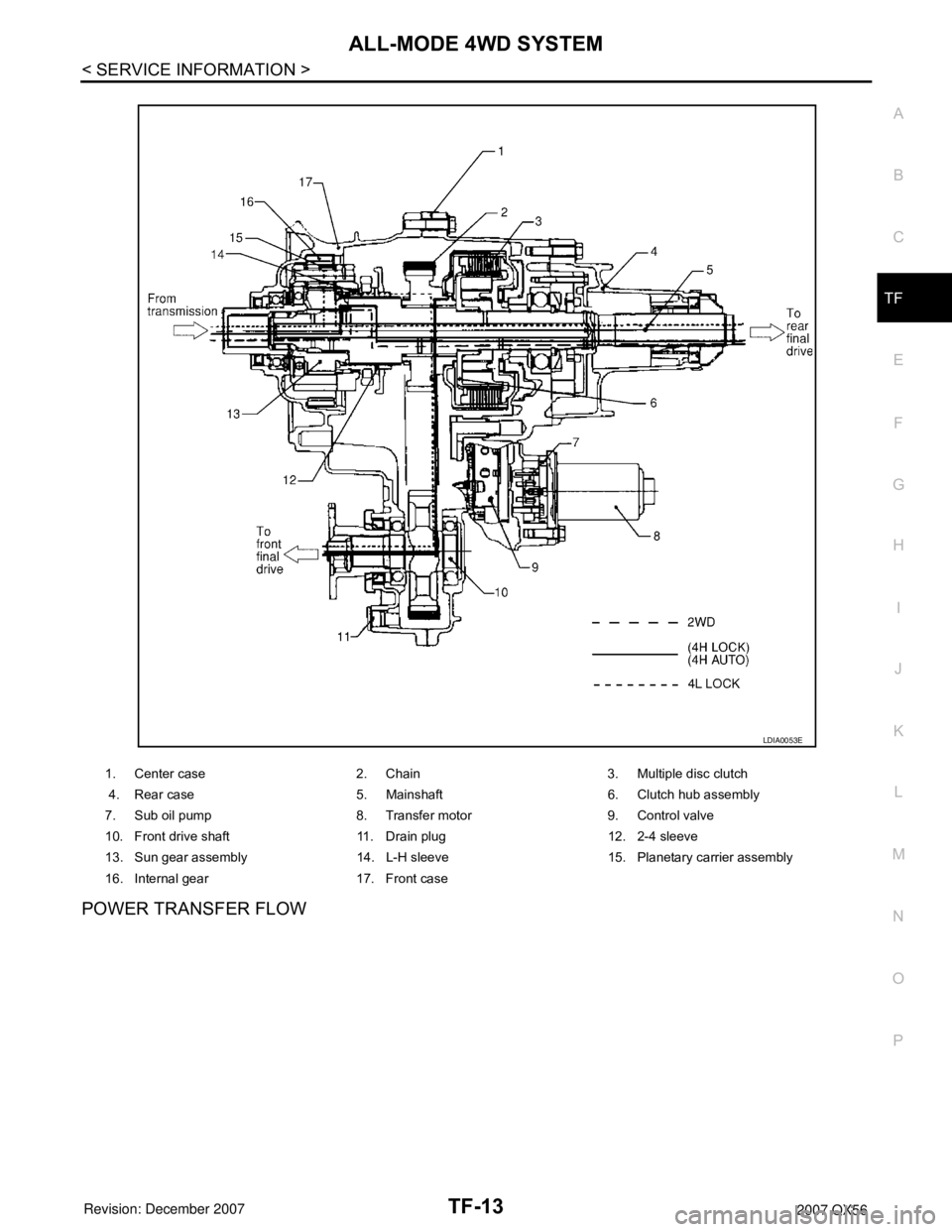
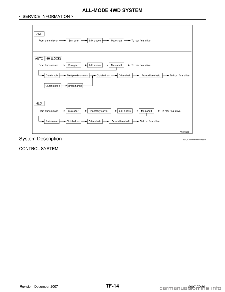
POWER TRANSFER FLOW
1. Center case 2. Chain 3. Multiple disc clutch
4. Rear case 5. Mainshaft 6. Clutch hub assembly
7. Sub oil pump 8. Transfer motor 9. Control valve
10. Front drive shaft 11. Drain plug 12. 2-4 sleeve
13. Sun gear assembly 14. L-H sleeve 15. Planetary carrier assembly
16. Internal gear 17. Front case
LDIA0053E
Page 2836 of 3061
TF-14
< SERVICE INFORMATION >
ALL-MODE 4WD SYSTEM
System Description
INFOID:0000000003532517
CONTROL SYSTEM
SDIA3327E