Page 2943 of 3061
TRANSFER CONTROL DEVICE
TF-121
< SERVICE INFORMATION >
C
E
F
G
H
I
J
K
L
MA
B
TF
N
O
P
TRANSFER CONTROL DEVICE
Removal and InstallationINFOID:0000000003532566
CAUTION:
• Change vehicle state to 2WD, and then remove and install transfer control device.
• Check 4WD shift indicator after installation. Refer to TF-3, "
Precaution for Transfer Assembly and
Transfer Control Unit Replacement".
1. Shift lever 2. Transfer control device
SDIA2654E
Page 2965 of 3061

TRANSFER ASSEMBLY
TF-143
< SERVICE INFORMATION >
C
E
F
G
H
I
J
K
L
MA
B
TF
N
O
P
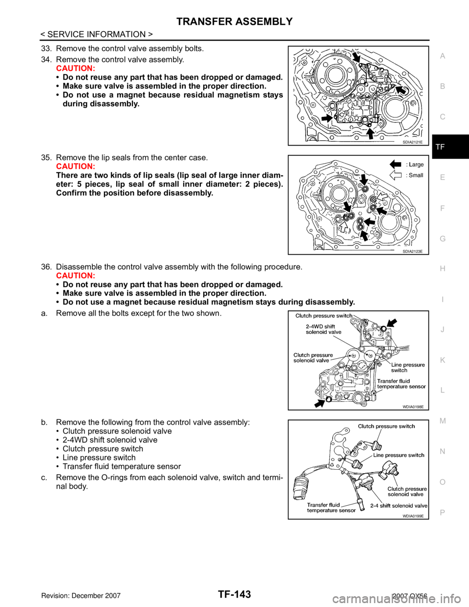
33. Remove the control valve assembly bolts.
34. Remove the control valve assembly.
CAUTION:
• Do not reuse any part that has been dropped or damaged.
• Make sure valve is assembled in the proper direction.
• Do not use a magnet because residual magnetism stays
during disassembly.
35. Remove the lip seals from the center case.
CAUTION:
There are two kinds of lip seals (lip seal of large inner diam-
eter: 5 pieces, lip seal of small inner diameter: 2 pieces).
Confirm the position before disassembly.
36. Disassemble the control valve assembly with the following procedure.
CAUTION:
• Do not reuse any part that has been dropped or damaged.
• Make sure valve is assembled in the proper direction.
• Do not use a magnet because residual magnetism stays during disassembly.
a. Remove all the bolts except for the two shown.
b. Remove the following from the control valve assembly:
• Clutch pressure solenoid valve
• 2-4WD shift solenoid valve
• Clutch pressure switch
• Line pressure switch
• Transfer fluid temperature sensor
c. Remove the O-rings from each solenoid valve, switch and termi-
nal body.
SDIA2121E
SDIA2123E
WDIA0198E
WDIA0199E
Page 2970 of 3061

TF-148
< SERVICE INFORMATION >
TRANSFER ASSEMBLY
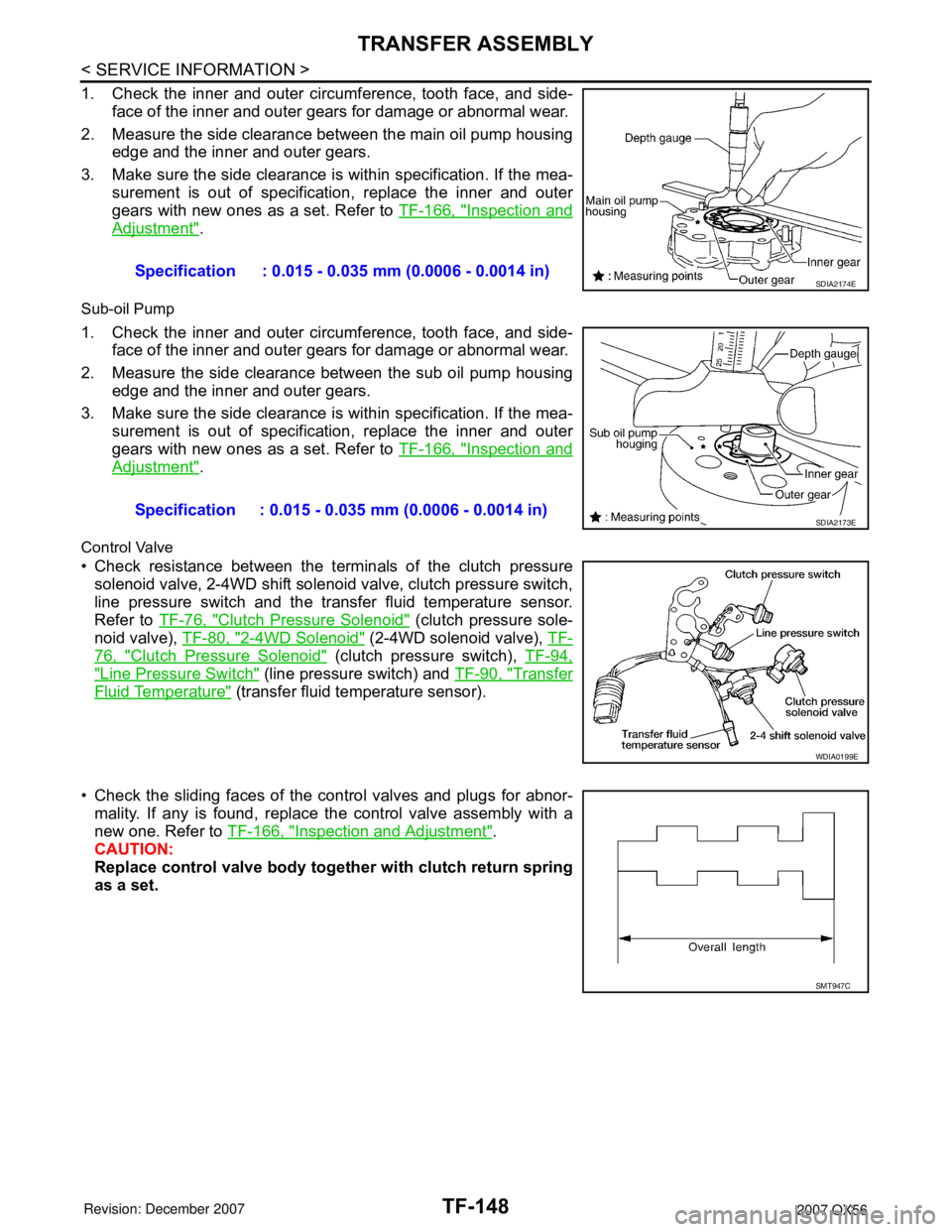
1. Check the inner and outer circumference, tooth face, and side-
face of the inner and outer gears for damage or abnormal wear.
2. Measure the side clearance between the main oil pump housing
edge and the inner and outer gears.
3. Make sure the side clearance is within specification. If the mea-
surement is out of specification, replace the inner and outer
gears with new ones as a set. Refer to TF-166, "
Inspection and
Adjustment".
Sub-oil Pump
1. Check the inner and outer circumference, tooth face, and side-
face of the inner and outer gears for damage or abnormal wear.
2. Measure the side clearance between the sub oil pump housing
edge and the inner and outer gears.
3. Make sure the side clearance is within specification. If the mea-
surement is out of specification, replace the inner and outer
gears with new ones as a set. Refer to TF-166, "
Inspection and
Adjustment".
Control Valve
• Check resistance between the terminals of the clutch pressure
solenoid valve, 2-4WD shift solenoid valve, clutch pressure switch,
line pressure switch and the transfer fluid temperature sensor.
Refer to TF-76, "
Clutch Pressure Solenoid" (clutch pressure sole-
noid valve), TF-80, "
2-4WD Solenoid" (2-4WD solenoid valve), TF-
76, "Clutch Pressure Solenoid" (clutch pressure switch), TF-94,
"Line Pressure Switch" (line pressure switch) and TF-90, "Transfer
Fluid Temperature" (transfer fluid temperature sensor).
• Check the sliding faces of the control valves and plugs for abnor-
mality. If any is found, replace the control valve assembly with a
new one. Refer to TF-166, "
Inspection and Adjustment".
CAUTION:
Replace control valve body together with clutch return spring
as a set.Specification : 0.015 - 0.035 mm (0.0006 - 0.0014 in)
SDIA2174E
Specification : 0.015 - 0.035 mm (0.0006 - 0.0014 in)SDIA2173E
WDIA0199E
SMT947C
Page 2974 of 3061

TF-152
< SERVICE INFORMATION >
TRANSFER ASSEMBLY
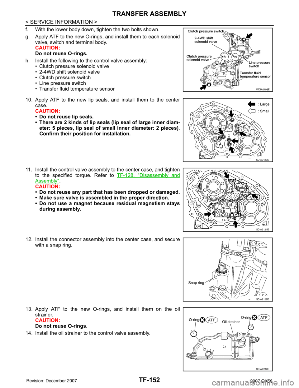
f. With the lower body down, tighten the two bolts shown.
g. Apply ATF to the new O-rings, and install them to each solenoid
valve, switch and terminal body.
CAUTION:
Do not reuse O-rings.
h. Install the following to the control valve assembly:
• Clutch pressure solenoid valve
• 2-4WD shift solenoid valve
• Clutch pressure switch
• Line pressure switch
• Transfer fluid temperature sensor
10. Apply ATF to the new lip seals, and install them to the center
case.
CAUTION:
• Do not reuse lip seals.
• There are 2 kinds of lip seals (lip seal of large inner diam-
eter: 5 pieces, lip seal of small inner diameter: 2 pieces).
Confirm their position for installation.
11. Install the control valve assembly to the center case, and tighten
to the specified torque. Refer to TF-128, "
Disassembly and
Assembly".
CAUTION:
• Do not reuse any part that has been dropped or damaged.
• Make sure valve is assembled in the proper direction.
• Do not use a magnet because residual magnetism stays
during assembly.
12. Install the connector assembly into the center case, and secure
with a snap ring.
13. Apply ATF to the new O-rings, and install them on the oil
strainer.
CAUTION:
Do not reuse O-rings.
14. Install the oil strainer to the control valve assembly.
WDIA0198E
SDIA2123E
SDIA2121E
SDIA2122E
SDIA2782E