2007 INFINITI QX56 engine
[x] Cancel search: enginePage 1808 of 3061
EM-38
< SERVICE INFORMATION >
TIMING CHAIN
Removal and Installation
INFOID:0000000003531533
NOTE:
• To remove timing chain and associated parts, start with those on the LH bank. The procedure for removing parts on the RH bank is omitted because it is the same as that for removal on the LH bank.
• To install timing chain and associated parts, start with those on the RH bank. The procedure for installing parts on the LH bank is omitted because it is t he same as that for installation on the RH bank.
REMOVAL
1. Remove the engine assembly from the vehicle. Refer to EM-74, "Removal and Installation".
2. Remove the following components and related parts: • Drive belt auto tensioner and idler pulley. Refer to EM-13, "
Removal and Installation".
• Thermostat housing and water hose. Refer to CO-20, "
Removal and Installation".
• Power steering oil pump bracket. Refer to LU-14, "
Removal and Installation".
• Oil pan (lower), (upper) and oil strainer. Refer to EM-24, "
Removal and Installation".
• Ignition coil. Refer to EM-28, "
Removal and Installation".
• Rocker cover. Refer to EM-35, "
Removal and Installation".
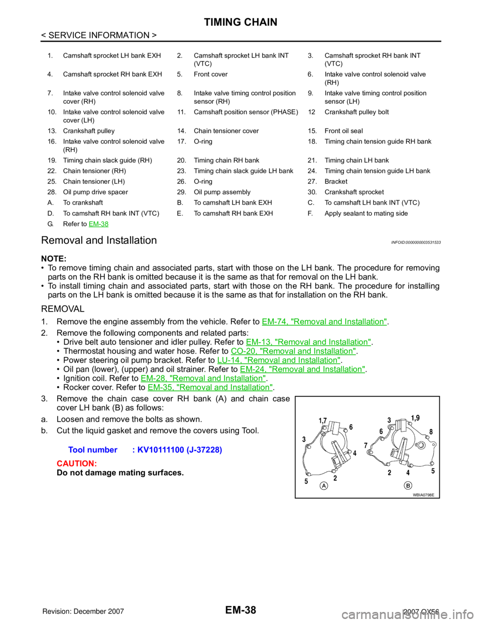
3. Remove the chain case cover RH bank (A) and chain case cover LH bank (B) as follows:
a. Loosen and remove the bolts as shown.
b. Cut the liquid gasket and remove the covers using Tool.
CAUTION:
Do not damage mating surfaces.
1. Camshaft sprocket LH bank EXH 2. Camshaft sprocket LH bank INT (VTC)3. Camshaft sprocket RH bank INT
(VTC)
4. Camshaft sprocket RH bank EXH 5. Front cover 6. Intake valve control solenoid valve (RH)
7. Intake valve control solenoid valve cover (RH) 8. Intake valve timing control position
sensor (RH) 9. Intake valve timing control position
sensor (LH)
10. Intake valve control solenoid valve cover (LH) 11. Camshaft position sensor (PHASE) 12 Crankshaft pulley bolt
13. Crankshaft pulley 14. Chain tensioner cover 15. Front oil seal
16. Intake valve control solenoid valve (RH) 17. O-ring 18. Timing chain tension guide RH bank
19. Timing chain slack guide (RH) 20. Timing chain RH bank 21. Timing chain LH bank
22. Chain tensioner (RH) 23. Timing chain slack guide LH bank 24. Timing chain tension guide LH bank
25. Chain tensioner (LH) 26. O-ring 27. Bracket
28. Oil pump drive spacer 29. Oil pump assembly 30. Crankshaft sprocket
A. To crankshaft B. To camshaft LH bank EXH C. To camshaft LH bank INT (VTC)
D. To camshaft RH bank INT (VTC) E. To camshaft RH bank EXH F. Apply sealant to mating side
G. Refer to EM-38
Tool number : KV10111100 (J-37228)
WBIA0798E
Page 1813 of 3061
TIMING CHAINEM-43
< SERVICE INFORMATION >
C
DE
F
G H
I
J
K L
M A
EM
NP
O
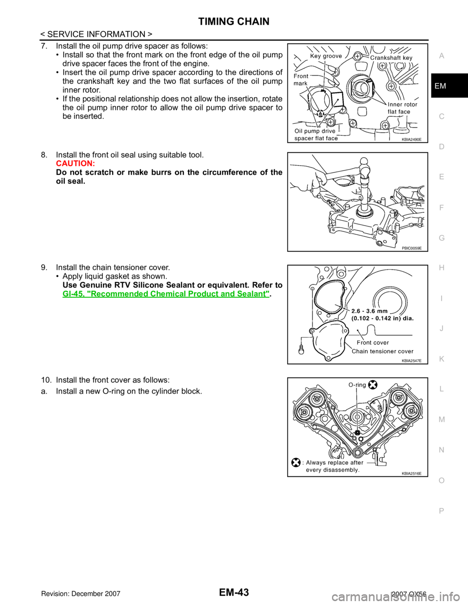
7. Install the oil pump drive spacer as follows:
• Install so that the front mark on the front edge of the oil pump
drive spacer faces the front of the engine.
• Insert the oil pump drive spacer according to the directions of
the crankshaft key and the two flat surfaces of the oil pump
inner rotor.
• If the positional relationship does not allow the insertion, rotate the oil pump inner rotor to allow the oil pump drive spacer to
be inserted.
8. Install the front oil seal using suitable tool. CAUTION:
Do not scratch or make burrs on the circumference of the
oil seal.
9. Install the chain tensioner cover. • Apply liquid gasket as shown.
Use Genuine RTV Silicone Seal ant or equivalent. Refer to
GI-45, "
Recommended Chemical Product and Sealant".
10. Install the front cover as follows:
a. Install a new O-ring on the cylinder block.
KBIA2490E
PBIC0059E
KBIA2547E
KBIA2516E
Page 1814 of 3061
EM-44
< SERVICE INFORMATION >
TIMING CHAIN
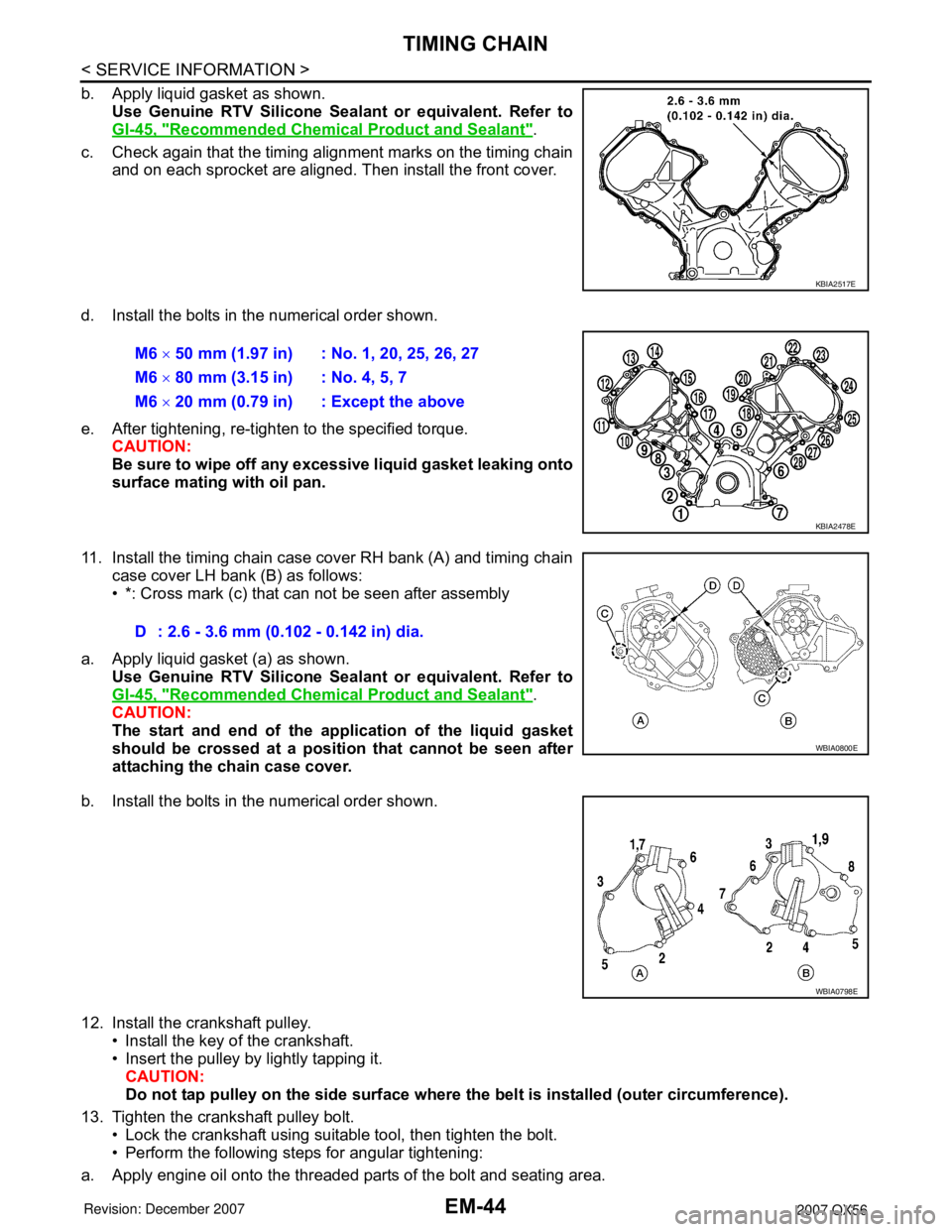
b. Apply liquid gasket as shown.Use Genuine RTV Silicone Seal ant or equivalent. Refer to
GI-45, "
Recommended Chemical Product and Sealant".
c. Check again that the timing alignment marks on the timing chain and on each sprocket are aligned. Then install the front cover.
d. Install the bolts in the numerical order shown.
e. After tightening, re-tighten to the specified torque. CAUTION:
Be sure to wipe off any excessive liquid gasket leaking onto
surface mating with oil pan.
11. Install the timing chain case cover RH bank (A) and timing chain case cover LH bank (B) as follows:
• *: Cross mark (c) that can not be seen after assembly
a. Apply liquid gasket (a) as shown. Use Genuine RTV Silicone Seal ant or equivalent. Refer to
GI-45, "
Recommended Chemical Product and Sealant".
CAUTION:
The start and end of the appl ication of the liquid gasket
should be crossed at a position that cannot be seen after
attaching the chain case cover.
b. Install the bolts in the numerical order shown.
12. Install the crankshaft pulley. • Install the key of the crankshaft.
• Insert the pulley by lightly tapping it.
CAUTION:
Do not tap pulley on the side surface where th e belt is installed (outer circumference).
13. Tighten the crankshaft pulley bolt. • Lock the crankshaft using suitable tool, then tighten the bolt.
• Perform the following steps for angular tightening:
a. Apply engine oil onto the threaded parts of the bolt and seating area.
KBIA2517E
M6 × 50 mm (1.97 in) : No. 1, 20, 25, 26, 27
M6 × 80 mm (3.15 in) : No. 4, 5, 7
M6 × 20 mm (0.79 in) : Except the above
KBIA2478E
D : 2.6 - 3.6 mm (0.102 - 0.142 in) dia.
WBIA0800E
WBIA0798E
Page 1815 of 3061
TIMING CHAINEM-45
< SERVICE INFORMATION >
C
DE
F
G H
I
J
K L
M A
EM
NP
O
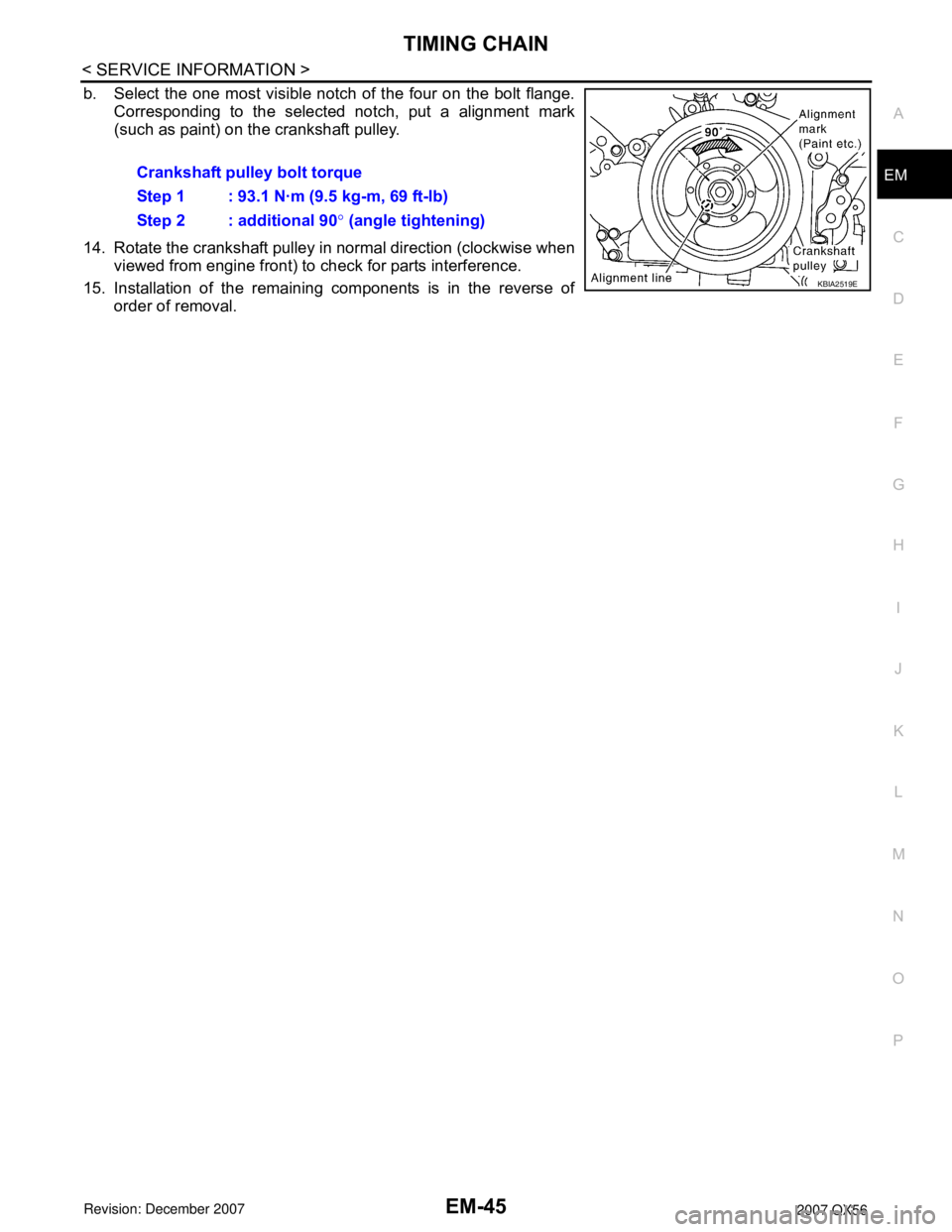
b. Select the one most visible notch of the four on the bolt flange.
Corresponding to the selected notch, put a alignment mark
(such as paint) on the crankshaft pulley.
14. Rotate the crankshaft pulley in normal direction (clockwise when viewed from engine front) to check for parts interference.
15. Installation of the remaining components is in the reverse of order of removal.Crankshaft pulley bolt torque
Step 1 : 93.1 N·m (9.5 kg-m, 69 ft-lb)
Step 2 : additional 90
° (angle tightening)
KBIA2519E
Page 1816 of 3061
EM-46
< SERVICE INFORMATION >
CAMSHAFT
CAMSHAFT
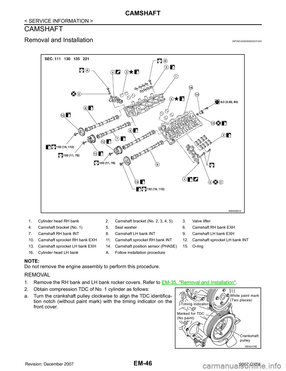
Removal and InstallationINFOID:0000000003531534
NOTE:
Do not remove the engine assembly to perform this procedure.
REMOVAL
1. Remove the RH bank and LH bank rocker covers. Refer to EM-35, "Removal and Installation".
2. Obtain compression TDC of No. 1 cylinder as follows:
a. Turn the crankshaft pulley clockwise to align the TDC identifica- tion notch (without paint mark) with the timing indicator on the
front cover.
1. Cylinder head RH bank 2. Camshaft bracket (No. 2, 3, 4, 5) 3. Valve lifter
4. Camshaft bracket (No. 1) 5. Seal washer 6. Camshaft RH bank EXH
7. Camshaft RH bank INT 8. Camshaft LH bank INT 9. Camshaft LH bank EXH
10. Camshaft sprocket RH bank EXH 11. Camshaft sprocket RH bank INT 12. Camshaft sprocket LH bank INT
13. Camshaft sprocket LH bank EXH 14. Camshaft position sensor (PHASE) 15. O-ring
16. Cylinder head LH bank A. Follow installation procedure
WBIA0801E
KBIA2476E
Page 1819 of 3061
CAMSHAFTEM-49
< SERVICE INFORMATION >
C
DE
F
G H
I
J
K L
M A
EM
NP
O
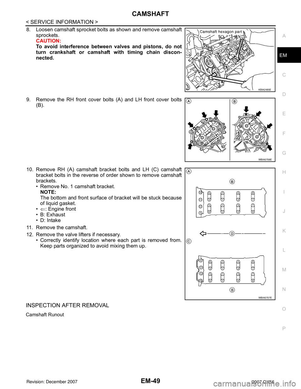
8. Loosen camshaft sprocket bolts as shown and remove camshaft
sprockets.
CAUTION:
To avoid interference between valves and pistons, do not
turn crankshaft or camshaft with timing chain discon-
nected.
9. Remove the RH front cover bolts (A) and LH front cover bolts (B).
10. Remove RH (A) camshaft bracket bolts and LH (C) camshaft bracket bolts in the reverse of order shown to remove camshaft
brackets.
• Remove No. 1 camshaft bracket.NOTE:
The bottom and front surface of bracket will be stuck because
of liquid gasket.
• ⇐ : Engine front
• B: Exhaust
• D: Intake
11. Remove the camshaft.
12. Remove the valve lifters if necessary. • Correctly identify location where each part is removed from.
Keep parts organized to avoid mixing them up.
INSPECTION AFTER REMOVAL
Camshaft Runout
KBIA2485E
WBIA0706E
WBIA0707E
Page 1825 of 3061
CAMSHAFTEM-55
< SERVICE INFORMATION >
C
DE
F
G H
I
J
K L
M A
EM
NP
O
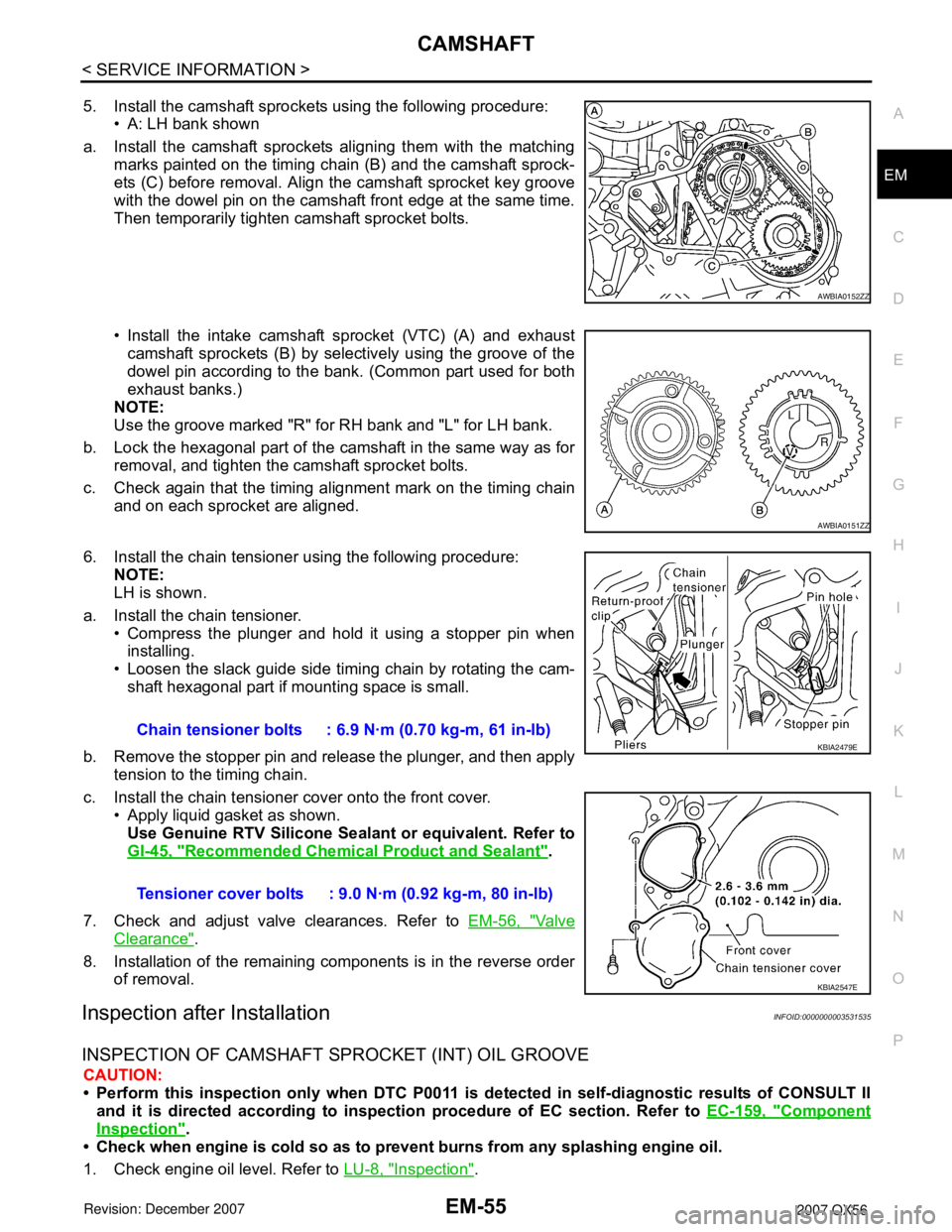
5. Install the camshaft sprockets using the following procedure:
• A: LH bank shown
a. Install the camshaft sprockets aligning them with the matching marks painted on the timing chain (B) and the camshaft sprock-
ets (C) before removal. Align the camshaft sprocket key groove
with the dowel pin on the camshaft front edge at the same time.
Then temporarily tighten camshaft sprocket bolts.
• Install the intake camshaft sprocket (VTC) (A) and exhaust
camshaft sprockets (B) by select ively using the groove of the
dowel pin according to the bank. (Common part used for both
exhaust banks.)
NOTE:
Use the groove marked "R" for RH bank and "L" for LH bank.
b. Lock the hexagonal part of the camshaft in the same way as for removal, and tighten the camshaft sprocket bolts.
c. Check again that the timing alignment mark on the timing chain and on each sprocket are aligned.
6. Install the chain tensioner using the following procedure: NOTE:
LH is shown.
a. Install the chain tensioner. • Compress the plunger and hold it using a stopper pin wheninstalling.
• Loosen the slack guide side timing chain by rotating the cam- shaft hexagonal part if mounting space is small.
b. Remove the stopper pin and release the plunger, and then apply tension to the timing chain.
c. Install the chain tensioner cover onto the front cover. • Apply liquid gasket as shown.
Use Genuine RTV Silicone Seal ant or equivalent. Refer to
GI-45, "
Recommended Chemical Product and Sealant".
7. Check and adjust valve clearances. Refer to EM-56, "
Va l v e
Clearance".
8. Installation of the remaining components is in the reverse order of removal.
Inspection after InstallationINFOID:0000000003531535
INSPECTION OF CAMSHAFT SPROCKET (INT) OIL GROOVE
CAUTION:
• Perform this inspection only when DTC P0011 is de tected in self-diagnostic results of CONSULT II
and it is directed according to inspect ion procedure of EC section. Refer to EC-159, "
Component
Inspection".
• Check when engine is cold so as to pr event burns from any splashing engine oil.
1. Check engine oil level. Refer to LU-8, "
Inspection".
AWBIA0152ZZ
AWBIA0151ZZ
Chain tensioner bolts : 6.9 N·m (0.70 kg-m, 61 in-lb)
Tensioner cover bolts : 9.0 N·m (0.92 kg-m, 80 in-lb)KBIA2479E
KBIA2547E
Page 1826 of 3061
EM-56
< SERVICE INFORMATION >
CAMSHAFT
2. Perform the following procedure so as to prevent the engine from being unintentionally started while
checking.
a. Release fuel pressure. Refer to EC-80, "
Fuel Pressure Check".
b. Disconnect ignition coil and injector harness connectors if practical.
3. Remove IVT control solenoid valve.
4. Crank engine, and then make sure that engine oil comes out from IVT control cover oil hole. End cranking
after checking.
WARNING:
Be careful not to touch rotating parts (drive be lts, idler pulley, and crankshaft pulley, etc.).
CAUTION:
• Engine oil may squirt from IVT control soleno id valve installation hole during cranking. Use a
shop cloth to prevent engine oil from splashin g on worker, engine components and vehicle.
• Do not allow engine oil to get on rubber compon ents such as drive belts or engine mount insula-
tors. Immediately wipe off any splashed engine oil.
5. Clean oil groove between oil strainer and IVT control solenoid valve if engine oil does not come out from IVT control valve cover oil hole. Refer to LU-7, "
Schematic".
6. Remove components between IVT control solenoid va lve and camshaft sprocket (INT), and then check
each oil groove for clogging.
• Clean oil groove if necessary.
7. After inspection, installation of the remaining components is in the reverse order of removal.
Valve ClearanceINFOID:0000000003531536
INSPECTION
NOTE:
Perform the following inspection after removal, installation or replacement of camshaft or valve-related parts,
or if there are unusual engine conditions due to changes in valve clearance over time (starting, idling, and/or
noise).
1. Warm up the engine. Then stop the engine.
2. Remove the engine cover and. Refer to EM-12, "
Removal and Installation".
3. Remove the battery cover. Refer to SC-8, "
Removal and Installation".
4. Remove the air cleaner and air duct assembly EM-15, "
Removal and Installation".
5. Remove the RH bank and LH bank rocker covers using power tool. Refer to EM-35, "
Removal and Instal-
lation".
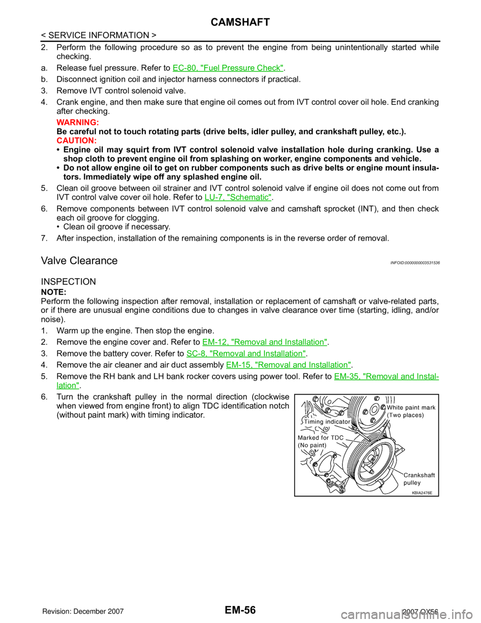
6. Turn the crankshaft pulley in the normal direction (clockwise when viewed from engine front) to align TDC identification notch
(without paint mark) with timing indicator.
KBIA2476E