Page 1827 of 3061
CAMSHAFTEM-57
< SERVICE INFORMATION >
C
DE
F
G H
I
J
K L
M A
EM
NP
O
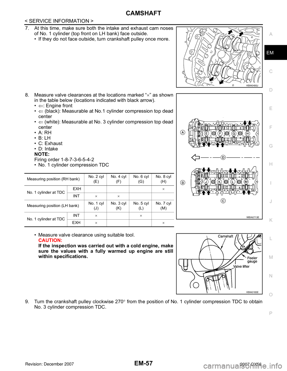
7. At this time, make sure both the intake and exhaust cam noses
of No. 1 cylinder (top front on LH bank) face outside.
• If they do not face outside, turn crankshaft pulley once more.
8. Measure valve clearances at the locations marked “ ×” as shown
in the table below (locations indicated with black arrow).
• ⇐ : Engine front
• ⇐ (black): Measurable at No.1 cylinder compression top dead
center
• ⇐ (white): Measurable at No. 3 cylinder compression top dead
center
•A: RH
•B: LH
• C: Exhaust
• D: Intake
NOTE:
Firing order 1-8-7-3-6-5-4-2
• No. 1 cylinder compression TDC
• Measure valve clearance using suitable tool. CAUTION:
If the inspection was carried out with a cold engine, make
sure the values with a fully warmed up engine are still
within specifications.
9. Turn the crankshaft pulley clockwise 270 ° from the position of No. 1 cylinder compression TDC to obtain
No. 3 cylinder compression TDC.
KBIA0400J
Measuring position (RH bank) No. 2 cyl
(E) No. 4 cyl
(F) No. 6 cyl
(G) No. 8 cyl
(H)
No. 1 cylinder at TDC EXH
×
INT ××
Measuring position (LH bank) No. 1 cyl
(J) No. 3 cyl
(K) No. 5 cyl
(L) No. 7 cyl
(M)
No. 1 cylinder at TDC INT
××
EXH ××
WBIA0713E
KBIA0185E
Page 1828 of 3061
EM-58
< SERVICE INFORMATION >
CAMSHAFT
10. Measure valve clearances at the locations marked “×” as shown
in the table below (locations indicated with white arrow).
• ⇐ : Engine front
• ⇐ (black): Measurable at No.1 cylinder compression top dead
center
• ⇐ (white): Measurable at No. 3 cylinder compression top dead
center
•A: RH
•B: LH
• C: Exhaust
•D: Intake
NOTE:
Firing order 1-8-7-2-3-6-5-4-2
• No. 3 cylinder compression TDC
• Measure valve clearance using suitable tool. CAUTION:
If the inspection was carried out with a cold engine, make
sure the values with a fully warmed up engine are still
within specifications.
Measuring position (RH bank) No. 2 cyl
(E) No. 4 cyl
(F) No. 6 cyl
(G) No. 8 cyl
(H)
No. 3 cylinder at TDC EXH
×
INT ×
Measuring position (LH bank) No. 1 cyl
(J) No. 3 cyl
(K) No. 5 cyl
(L) No. 7 cyl
(M)
No. 3 cylinder at TDC INT
××
EXH ××
WBIA0713E
KBIA0185E
Page 1829 of 3061
CAMSHAFTEM-59
< SERVICE INFORMATION >
C
DE
F
G H
I
J
K L
M A
EM
NP
O
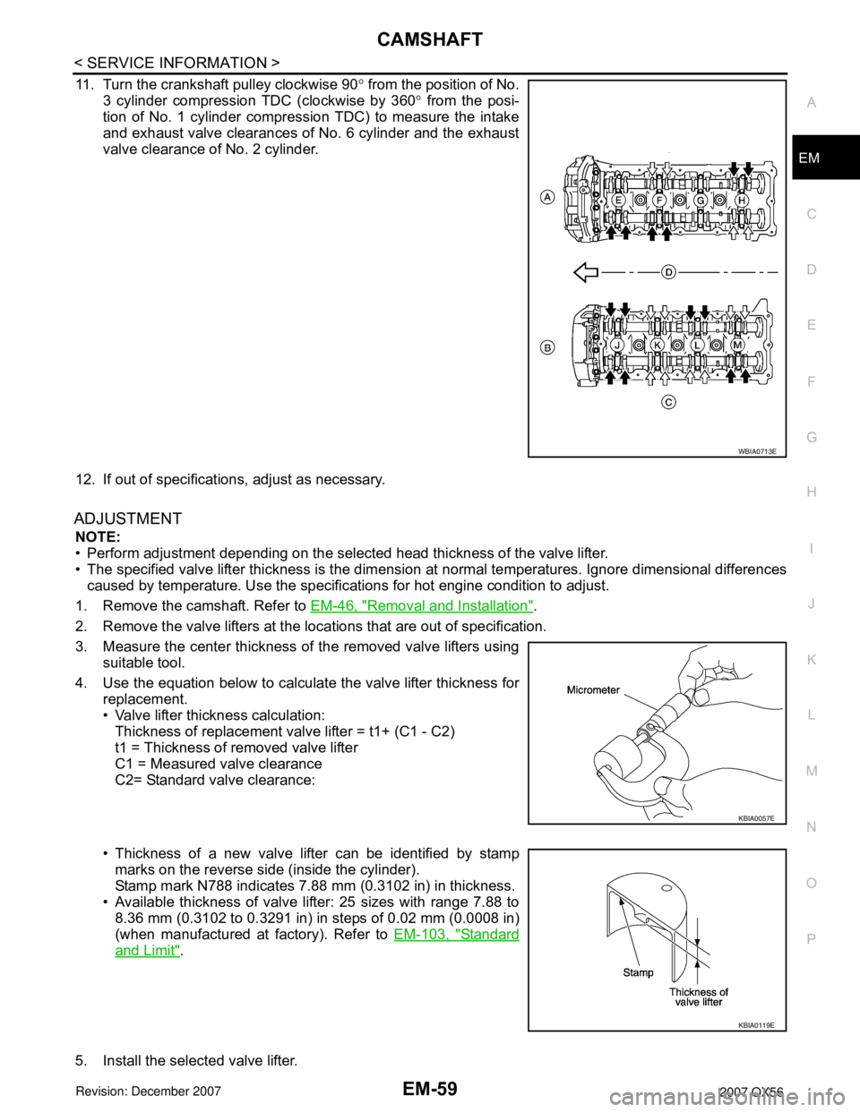
11. Turn the crankshaft pulley clockwise 90
° from the position of No.
3 cylinder compression TDC (clockwise by 360 ° from the posi-
tion of No. 1 cylinder compression TDC) to measure the intake
and exhaust valve clearances of No. 6 cylinder and the exhaust
valve clearance of No. 2 cylinder.
12. If out of specifications, adjust as necessary.
ADJUSTMENT
NOTE:
• Perform adjustment depending on the selected head thickness of the valve lifter.
• The specified valve lifter thickness is the dimension at normal temperatures. Ignore dimensional differences
caused by temperature. Us e the specifications for hot engine condition to adjust.
1. Remove the camshaft. Refer to EM-46, "
Removal and Installation".
2. Remove the valve lifters at the loca tions that are out of specification.
3. Measure the center thickness of the removed valve lifters using suitable tool.
4. Use the equation below to calculate the valve lifter thickness for replacement.
• Valve lifter thickness calculation:
Thickness of replacement valve lifter = t1+ (C1 - C2)
t1 = Thickness of removed valve lifter
C1 = Measured valve clearance
C2= Standard valve clearance:
• Thickness of a new valve lifter can be identified by stamp marks on the reverse side (inside the cylinder).
Stamp mark N788 indicates 7.88 mm (0.3102 in) in thickness.
• Available thickness of valve lifter: 25 sizes with range 7.88 to 8.36 mm (0.3102 to 0.3291 in) in steps of 0.02 mm (0.0008 in)
(when manufactured at factory). Refer to EM-103, "
Standard
and Limit".
5. Install the selected valve lifter.
WBIA0713E
KBIA0057E
KBIA0119E
Page 1830 of 3061
EM-60
< SERVICE INFORMATION >
CAMSHAFT
6. Install the camshaft.
7. Manually turn the crankshaft pulley a few turns.
8. Make sure the valve clearances for a cold engine are within specifications by referring to the specified val-
ues.
9. After completing the repair, check the valve clearanc es again with the specifications for a warmed engine.
Make sure the values are within specifications.
Page 1831 of 3061
OIL SEALEM-61
< SERVICE INFORMATION >
C
DE
F
G H
I
J
K L
M A
EM
NP
O
OIL SEAL
Removal and Installation of Valve Oil SealINFOID:0000000003531537
REMOVAL
1. Remove the camshaft relating to the valve oil seal to be removed. Refer to
EM-46, "Removal and Installa-
tion".
2. Remove the valve lifters. Refer to EM-65, "
Removal and Installation".
• Correctly identify the location where each part is removed from. Keep parts organized to avoid mixing
them up.
3. Turn the crankshaft until the cylinder requiring new oil seals is at TDC. This will prevent the valve from
dropping into the cylinder.
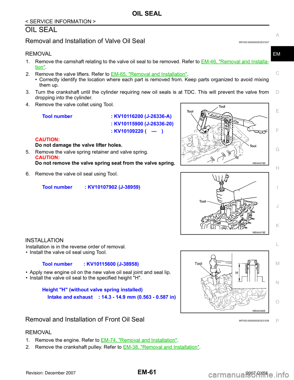
4. Remove the valve collet using Tool.
CAUTION:
Do not damage the valve lifter holes.
5. Remove the valve spring retainer and valve spring. CAUTION:
Do not remove the valve spring seat from the valve spring.
6. Remove the valve oil seal using Tool.
INSTALLATION
Installation is in the reverse order of removal.
• Install the valve oil seal using Tool.
• Apply new engine oil on the new valve oil seal joint and seal lip.
• Install the valve oil seal to the specified height "H".
Removal and Installati on of Front Oil SealINFOID:0000000003531538
REMOVAL
1. Remove the engine. Refer to EM-74, "Removal and Installation".
2. Remove the crankshaft pulley. Refer to EM-38, "
Removal and Installation".
Tool number : KV10116200 (J-26336-A)
: KV10115900 (J-26336-20)
: KV10109220 ( — )
WBIA0578E
Tool number : KV10107902 (J-38959)
WBIA0478E
Tool number : KV10115600 (J-38958)
Height "H" (without valve spring installed)Intake and exhaust : 14.3 - 14.9 mm (0.563 - 0.587 in)
WBIA0490E
Page 1832 of 3061
EM-62
< SERVICE INFORMATION >
OIL SEAL
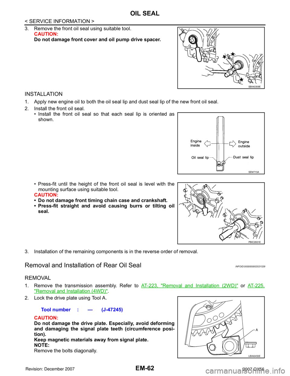
3. Remove the front oil seal using suitable tool.CAUTION:
Do not damage front cover and oil pump drive spacer.
INSTALLATION
1. Apply new engine oil to both the oil seal lip and dust seal lip of the new front oil seal.
2. Install the front oil seal.• Install the front oil seal so that each seal lip is oriented as
shown.
• Press-fit until the height of the front oil seal is level with the mounting surface using suitable tool.
CAUTION:
• Do not damage front timing chain case and crankshaft.
• Press-fit straight and avoid causing burrs or tilting oil
seal.
3. Installation of the remaining components is in the reverse order of removal.
Removal and Installation of Rear Oil SealINFOID:0000000003531539
REMOVAL
1. Remove the transmission assembly. Refer to AT-223, "Removal and Installation (2WD)" or AT-225,
"Removal and Installation (4WD)".
2. Lock the drive plate using Tool A.
CAUTION:
Do not damage the drive plat e. Especially, avoid deforming
and damaging the signal plat e teeth (circumference posi-
tion).
Keep magnetic materials away from signal plate.
NOTE:
Remove the bolts diagonally.
SBIA0359E
SEM715A
PBIC2931E
Tool number : — (J-47245)
LBIA0455E
Page 1833 of 3061
OIL SEALEM-63
< SERVICE INFORMATION >
C
DE
F
G H
I
J
K L
M A
EM
NP
O
3. Remove the drive plate.
CAUTION:
Place the drive plate with the si gnal plate surface facing upward.
4. Remove the engine rear plate.
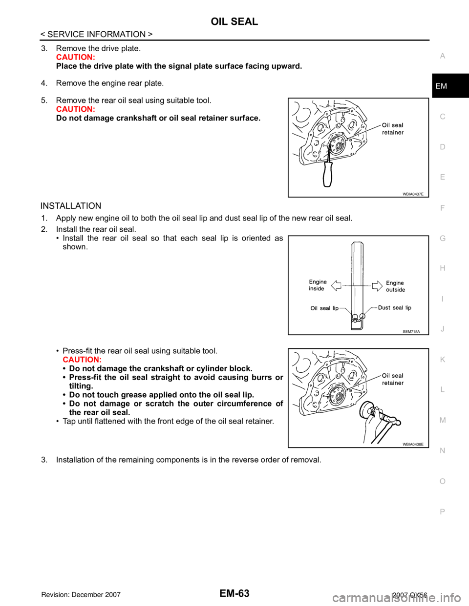
5. Remove the rear oil seal using suitable tool. CAUTION:
Do not damage crankshaft or oil seal retainer surface.
INSTALLATION
1. Apply new engine oil to both the oil seal lip and dust seal lip of the new rear oil seal.
2. Install the rear oil seal.• Install the rear oil seal so that each seal lip is oriented asshown.
• Press-fit the rear oil seal using suitable tool. CAUTION:
• Do not damage the crankshaft or cylinder block.
• Press-fit the oil seal straight to avoid causing burrs or
tilting.
• Do not touch grease applied onto the oil seal lip.
• Do not damage or scratch the outer circumference of the rear oil seal.
• Tap until flattened with the front edge of the oil seal retainer.
3. Installation of the remaining components is in the reverse order of removal.
WBIA0437E
SEM715A
WBIA0438E
Page 1834 of 3061
EM-64
< SERVICE INFORMATION >
CYLINDER HEAD
CYLINDER HEAD
On-Vehicle ServiceINFOID:0000000003531540
CHECKING COMPRESSION PRESSURE
1. Warm up the engine thoroughly. Then stop the engine.
2. Release the fuel pressure. Refer to EC-80, "
Fuel Pressure Check".
CAUTION:
If CONSULT-II is not used to release fuel pressure leave the fu el pump fuse disconnected until
step 7.
3. Remove the spark plug from each cylinder. Refer to EM-29, "
Removal and Installation".
4. Connect the engine tachometer (not required in use of CONSULT-II).
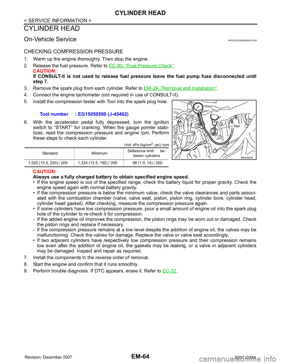
5. Install the compression tester with Tool into the spark plug hole.
6. With the accelerator pedal fully depressed, turn the ignition switch to “START” for cranking. When the gauge pointer stabi-
lizes, read the compression pressure and engine rpm. Perform
these steps to check each cylinder.
Unit: kPa (kg/cm2, psi) /rpm
CAUTION:
Always use a fully charged battery to obtain specified engine speed.
• If the engine speed is out of the specified range, che ck the battery liquid for proper gravity. Check the
engine speed again with normal battery gravity.
• If the compression pressure is below the minimum value, check the valve clearances and parts associ- ated with the combustion chamber (valve, valve seat , piston, piston ring, cylinder bore, cylinder head,
cylinder head gasket). After checking, measure the compression pressure again.
• If some cylinders have low compression pressure, pour a small amount of engine oil into the spark plug hole of the cylinder to re-check it for compression.
- If the added engine oil improves the compression, t he piston rings may be worn out or damaged. Check
the piston rings and replace if necessary.
- If the compression pressure remains at a low level despite the addition of engine oil, the valves may be
malfunctioning. Check the valves for damage. R eplace the valve or valve seat accordingly.
• If two adjacent cylinders have respectively low co mpression pressure and their compression remains
low even after the addition of engine oil, the gaskets may be leaking, or a valve in adjacent cylinders
may be damaged. Inspect and repair as required.
7. Install the components in the reverse order of removal.
8. Start the engine and confirm that it runs smoothly.
9. Perform trouble diagnosis. If DTC appears, erase it. Refer to EC-32
.
Tool number : EG15050500 (J-45402)
Standard Minimum
Deference limit be-
tween cylinders
1,520 (15.5, 220) / 200 1,324 (13.5, 192) / 200 98 (1.0, 14) / 200WBIA0605E