2007 INFINITI QX56 battery
[x] Cancel search: batteryPage 3013 of 3061
WT-24
< SERVICE INFORMATION >
TROUBLE DIAGNOSIS FOR SYMPTOMS
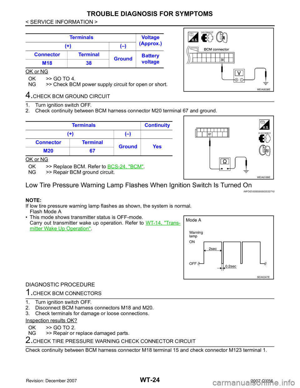
OK or NG
OK >> GO TO 4.
NG >> Check BCM power supply circuit for open or short.
4.CHECK BCM GROUND CIRCUIT
1. Turn ignition switch OFF.
2. Check continuity between BCM harness connector M20 terminal 67 and ground.
OK or NG
OK >> Replace BCM. Refer to BCS-24, "BCM".
NG >> Repair BCM ground circuit.
Low Tire Pressure Warning Lamp Flashes When Ignition Switch Is Turned On
INFOID:0000000003532710
NOTE:
If low tire pressure warning lamp flashes as shown, the system is normal.
Flash Mode A
• This mode shows transmitter status is OFF-mode.
Carry out transmitter wake up operation. Refer to WT-14, "
Trans-
mitter Wake Up Operation".
DIAGNOSTIC PROCEDURE
1.CHECK BCM CONNECTORS
1. Turn ignition switch OFF.
2. Disconnect BCM harness connectors M18 and M20.
3. Check terminals for damage or loose connections.
Inspection results OK?
OK >> GO TO 2.
NG >> Repair or replace damaged parts.
2.CHECK TIRE PRESSURE WARNING CHECK CONNECTOR CIRCUIT
Check continuity between BCM harness connector M18 terminal 15 and check connector M123 terminal 1. Terminals Voltage
(Approx.)
(+) (–)
Connector Terminal
GroundBattery
voltage
M18 38
WEIA0038E
Terminals Continuity
(+) (–)
Connector Terminal
Ground Yes
M20 67
WEIA0189E
SEIA0347E
Page 3027 of 3061
WW-10
< SERVICE INFORMATION >
FRONT WIPER AND WASHER SYSTEM
Work Flow
INFOID:0000000003533558
1. Confirm the trouble symptom or customer complaint.
2. Understand the system description, refer to WW-3, "
System Description".
3. Perform preliminary inspection, refer to WW-10, "
Preliminary Check".
4. Check symptom and repair or replace the cause of malfunction.
5. Does wiper function operate normally? If it operates normally, GO TO 6. If not, GO TO 4.
6. Inspection End.
Preliminary CheckINFOID:0000000003533559
INSPECTION FOR POWER SUPPLY AND GROUND CIRCUIT
Inspection procedure
1.CHECK FUSE
Check if wiper or washer fuse is blown.
OK or NG
OK >> GO TO 2.
NG >> If fuse is blown, be sure to eliminate cause of blown fuse before installing new fuse.
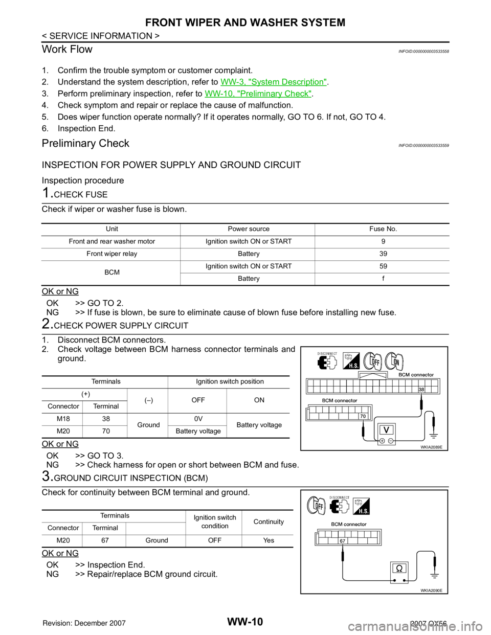
2.CHECK POWER SUPPLY CIRCUIT
1. Disconnect BCM connectors.
2. Check voltage between BCM harness connector terminals and
ground.
OK or NG
OK >> GO TO 3.
NG >> Check harness for open or short between BCM and fuse.
3.GROUND CIRCUIT INSPECTION (BCM)
Check for continuity between BCM terminal and ground.
OK or NG
OK >> Inspection End.
NG >> Repair/replace BCM ground circuit.
Unit Power source Fuse No.
Front and rear washer motor Ignition switch ON or START 9
Front wiper relay Battery 39
BCMIgnition switch ON or START 59
Battery f
Terminals Ignition switch position
(+)
(–) OFF ON
Connector Terminal
M18 38
Ground0V
Battery voltage
M20 70 Battery voltage
WKIA2089E
Te r m i n a l s
Ignition switch
conditionContinuity
Connector Terminal
M20 67 Ground OFF Yes
WKIA2090E
Page 3031 of 3061
WW-14
< SERVICE INFORMATION >
FRONT WIPER AND WASHER SYSTEM
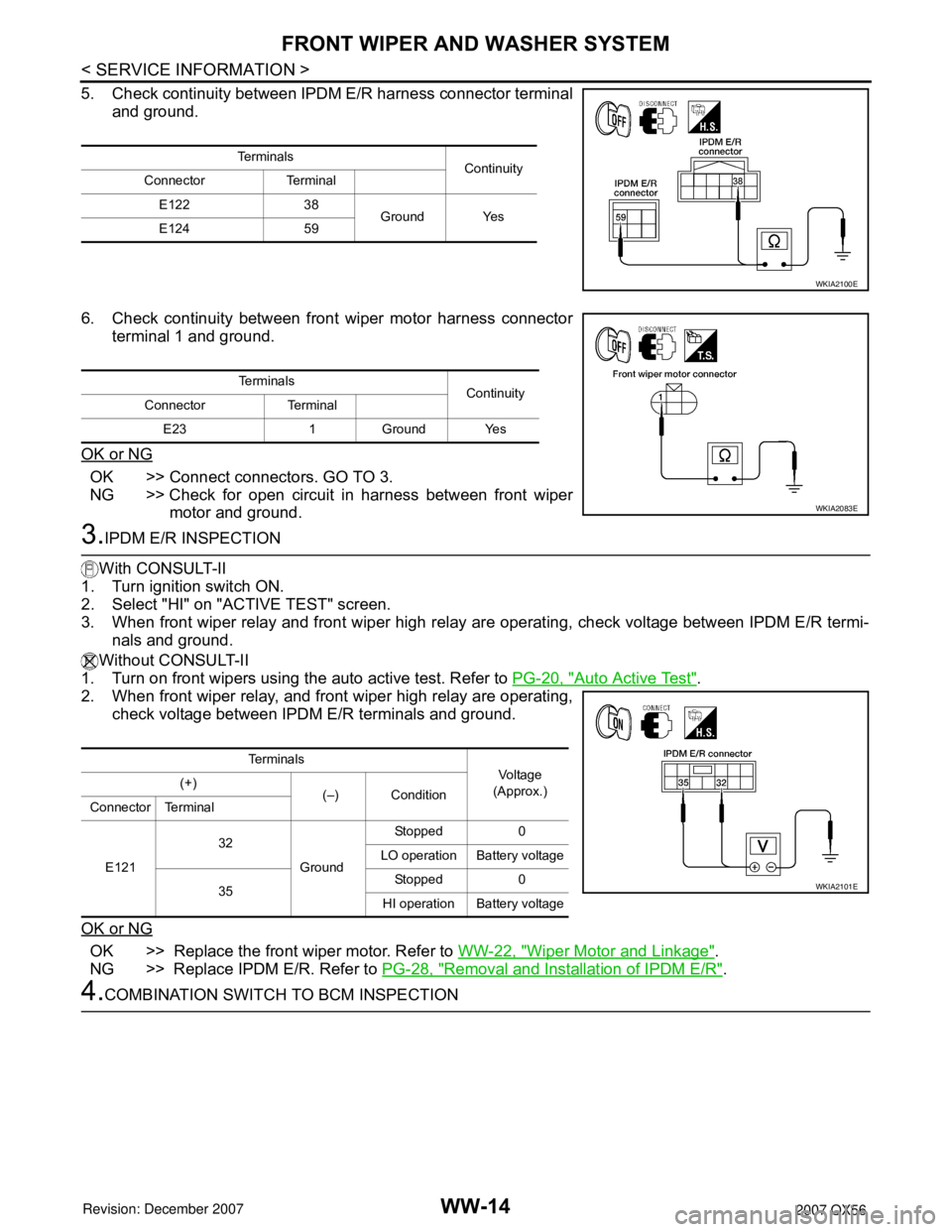
5. Check continuity between IPDM E/R harness connector terminal
and ground.
6. Check continuity between front wiper motor harness connector
terminal 1 and ground.
OK or NG
OK >> Connect connectors. GO TO 3.
NG >> Check for open circuit in harness between front wiper
motor and ground.
3.IPDM E/R INSPECTION
With CONSULT-II
1. Turn ignition switch ON.
2. Select "HI" on "ACTIVE TEST" screen.
3. When front wiper relay and front wiper high relay are operating, check voltage between IPDM E/R termi-
nals and ground.
Without CONSULT-II
1. Turn on front wipers using the auto active test. Refer to PG-20, "
Auto Active Test".
2. When front wiper relay, and front wiper high relay are operating,
check voltage between IPDM E/R terminals and ground.
OK or NG
OK >> Replace the front wiper motor. Refer to WW-22, "Wiper Motor and Linkage".
NG >> Replace IPDM E/R. Refer to PG-28, "
Removal and Installation of IPDM E/R".
4.COMBINATION SWITCH TO BCM INSPECTION
Te r m i n a l s
Continuity
Connector Terminal
E122 38
Ground Yes
E124 59
WKIA2100E
Te r m i n a l s
Continuity
Connector Terminal
E23 1 Ground Yes
WKIA2083E
Te r m i n a l s
Vol tag e
(Approx.) (+)
(–) Condition
Connector Terminal
E12132
GroundStopped 0
LO operation Battery voltage
35Stopped 0
HI operation Battery voltage
WKIA2101E
Page 3033 of 3061
WW-16
< SERVICE INFORMATION >
FRONT WIPER AND WASHER SYSTEM
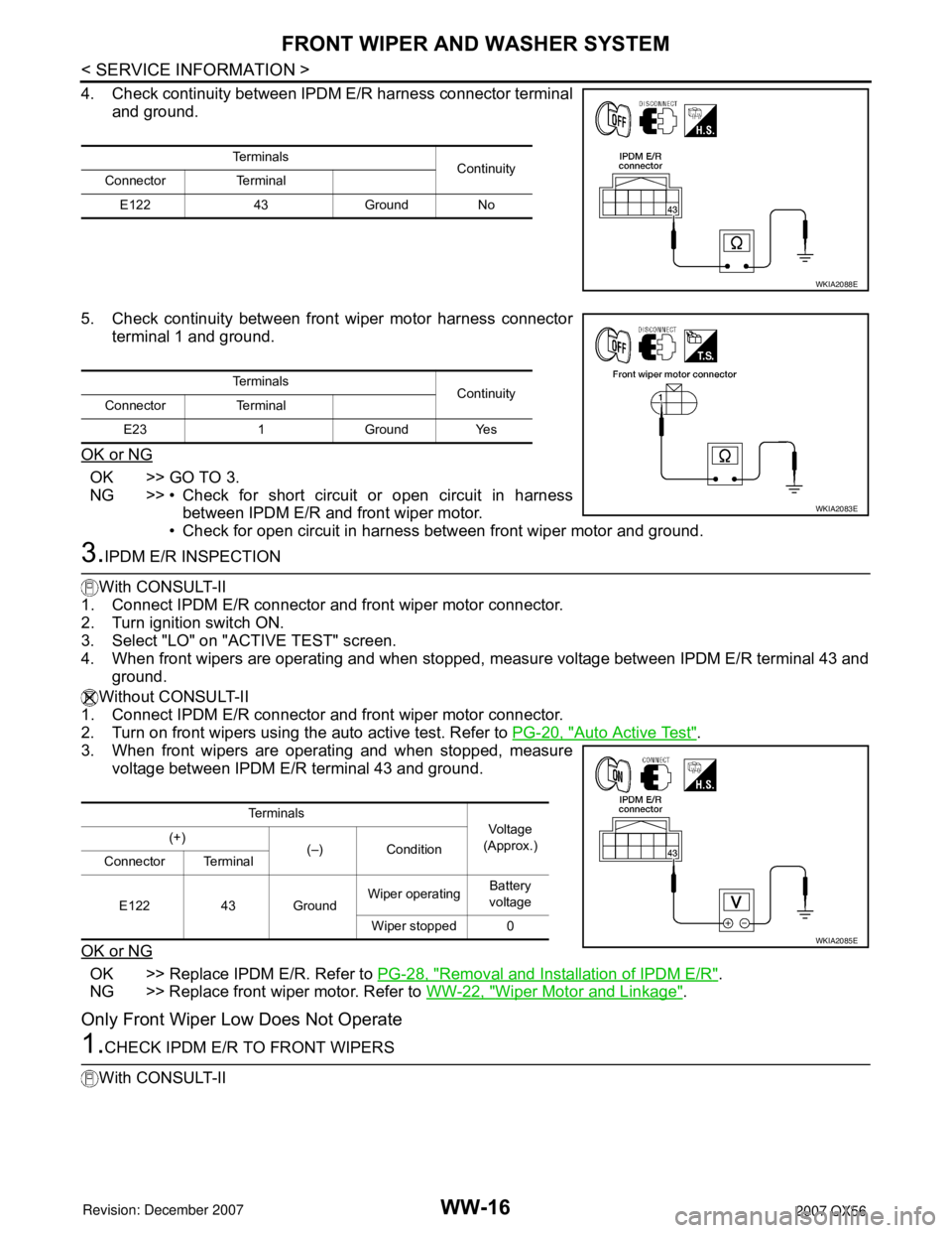
4. Check continuity between IPDM E/R harness connector terminal
and ground.
5. Check continuity between front wiper motor harness connector
terminal 1 and ground.
OK or NG
OK >> GO TO 3.
NG >> • Check for short circuit or open circuit in harness
between IPDM E/R and front wiper motor.
• Check for open circuit in harness between front wiper motor and ground.
3.IPDM E/R INSPECTION
With CONSULT-II
1. Connect IPDM E/R connector and front wiper motor connector.
2. Turn ignition switch ON.
3. Select "LO" on "ACTIVE TEST" screen.
4. When front wipers are operating and when stopped, measure voltage between IPDM E/R terminal 43 and
ground.
Without CONSULT-II
1. Connect IPDM E/R connector and front wiper motor connector.
2. Turn on front wipers using the auto active test. Refer to PG-20, "
Auto Active Test".
3. When front wipers are operating and when stopped, measure
voltage between IPDM E/R terminal 43 and ground.
OK or NG
OK >> Replace IPDM E/R. Refer to PG-28, "Removal and Installation of IPDM E/R".
NG >> Replace front wiper motor. Refer to WW-22, "
Wiper Motor and Linkage".
Only Front Wiper Low Does Not Operate
1.CHECK IPDM E/R TO FRONT WIPERS
With CONSULT-II
Te r m i n a l s
Continuity
Connector Terminal
E122 43 Ground No
WKIA2088E
Te r m i n a l s
Continuity
Connector Terminal
E23 1 Ground Yes
WKIA2083E
Te r m i n a l s
Vol tag e
(Approx.) (+)
(–) Condition
Connector Terminal
E122 43 GroundWiper operatingBattery
voltage
Wiper stopped 0
WKIA2085E
Page 3034 of 3061
FRONT WIPER AND WASHER SYSTEM
WW-17
< SERVICE INFORMATION >
C
D
E
F
G
H
I
J
L
MA
B
WW
N
O
P
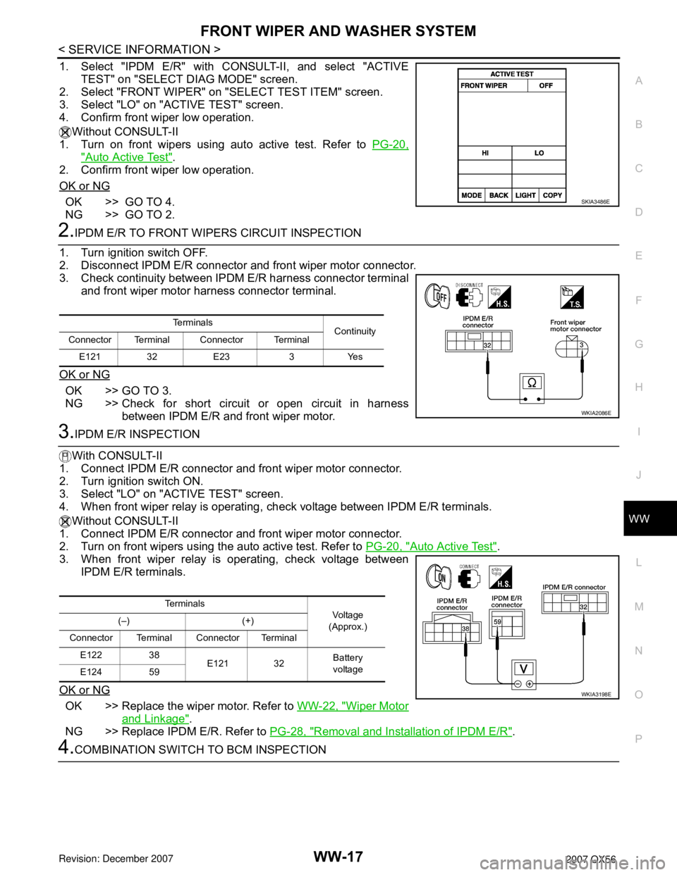
1. Select "IPDM E/R" with CONSULT-II, and select "ACTIVE
TEST" on "SELECT DIAG MODE" screen.
2. Select "FRONT WIPER" on "SELECT TEST ITEM" screen.
3. Select "LO" on "ACTIVE TEST" screen.
4. Confirm front wiper low operation.
Without CONSULT-II
1. Turn on front wipers using auto active test. Refer to PG-20,
"Auto Active Test".
2. Confirm front wiper low operation.
OK or NG
OK >> GO TO 4.
NG >> GO TO 2.
2.IPDM E/R TO FRONT WIPERS CIRCUIT INSPECTION
1. Turn ignition switch OFF.
2. Disconnect IPDM E/R connector and front wiper motor connector.
3. Check continuity between IPDM E/R harness connector terminal
and front wiper motor harness connector terminal.
OK or NG
OK >> GO TO 3.
NG >> Check for short circuit or open circuit in harness
between IPDM E/R and front wiper motor.
3.IPDM E/R INSPECTION
With CONSULT-II
1. Connect IPDM E/R connector and front wiper motor connector.
2. Turn ignition switch ON.
3. Select "LO" on "ACTIVE TEST" screen.
4. When front wiper relay is operating, check voltage between IPDM E/R terminals.
Without CONSULT-II
1. Connect IPDM E/R connector and front wiper motor connector.
2. Turn on front wipers using the auto active test. Refer to PG-20, "
Auto Active Test".
3. When front wiper relay is operating, check voltage between
IPDM E/R terminals.
OK or NG
OK >> Replace the wiper motor. Refer to WW-22, "Wiper Motor
and Linkage".
NG >> Replace IPDM E/R. Refer to PG-28, "
Removal and Installation of IPDM E/R".
4.COMBINATION SWITCH TO BCM INSPECTION
SKIA3486E
Te r m i n a l s
Continuity
Connector Terminal Connector Terminal
E121 32 E23 3 Yes
WKIA2086E
Te r m i n a l s
Vo l ta g e
(Approx.) (–) (+)
Connector Terminal Connector Terminal
E122 38
E121 32Battery
voltage
E124 59
WKIA3198E
Page 3036 of 3061
FRONT WIPER AND WASHER SYSTEM
WW-19
< SERVICE INFORMATION >
C
D
E
F
G
H
I
J
L
MA
B
WW
N
O
P
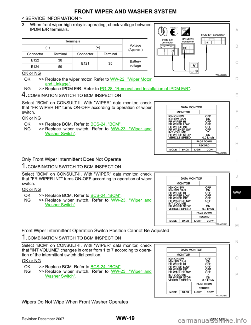
3. When front wiper high relay is operating, check voltage between
IPDM E/R terminals.
OK or NG
OK >> Replace the wiper motor. Refer to WW-22, "Wiper Motor
and Linkage".
NG >> Replace IPDM E/R. Refer to PG-28, "
Removal and Installation of IPDM E/R".
4.COMBINATION SWITCH TO BCM INSPECTION
Select "BCM" on CONSULT-II. With "WIPER" data monitor, check
that "FR WIPER HI" turns ON-OFF according to operation of wiper
switch.
OK or NG
OK >> Replace BCM. Refer to BCS-24, "BCM".
NG >> Replace wiper switch. Refer to WW-23, "
Wiper and
Washer Switch".
Only Front Wiper Intermittent Does Not Operate
1.COMBINATION SWITCH TO BCM INSPECTION
Select "BCM" on CONSULT-II. With "WIPER" data monitor, check
that "FR WIPER INT" turns ON-OFF according to operation of wiper
switch.
OK or NG
OK >> Replace BCM. Refer to BCS-24, "BCM".
NG >> Replace wiper switch. Refer to WW-23, "
Wiper and
Washer Switch".
Front Wiper Intermittent Operation Switch Position Cannot Be Adjusted
1.COMBINATION SWITCH TO BCM INSPECTION
Select "BCM" on CONSULT-II. With "WIPER" data monitor, check
that "INT VOLUME" changes in order from 1 to 7 according to opera-
tion of the intermittent switch dial position.
OK or NG
OK >> Replace BCM. Refer to BCS-24, "BCM".
NG >> Replace wiper switch. Refer to WW-23, "
Wiper and
Washer Switch".
Wipers Do Not Wipe When Front Washer Operates
Te r m i n a l s
Vo l ta g e
(Approx.) (–) (+)
Connector Terminal Connector Terminal
E122 38
E121 35Battery
voltage
E124 59
WKIA3200E
WKIA1018E
WKIA1018E
WKIA1018E
Page 3038 of 3061
FRONT WIPER AND WASHER SYSTEM
WW-21
< SERVICE INFORMATION >
C
D
E
F
G
H
I
J
L
MA
B
WW
N
O
P
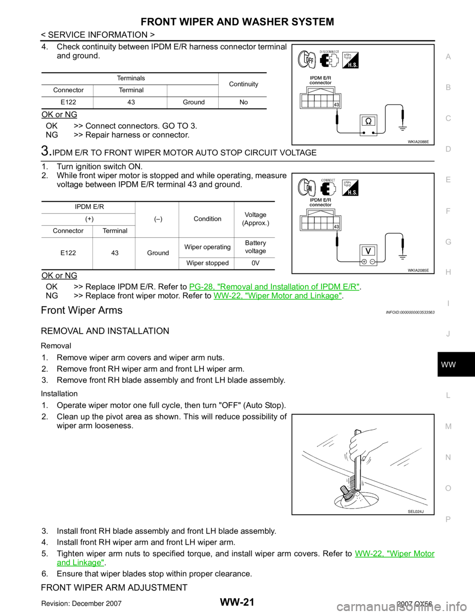
4. Check continuity between IPDM E/R harness connector terminal
and ground.
OK or NG
OK >> Connect connectors. GO TO 3.
NG >> Repair harness or connector.
3.IPDM E/R TO FRONT WIPER MOTOR AUTO STOP CIRCUIT VOLTAGE
1. Turn ignition switch ON.
2. While front wiper motor is stopped and while operating, measure
voltage between IPDM E/R terminal 43 and ground.
OK or NG
OK >> Replace IPDM E/R. Refer to PG-28, "Removal and Installation of IPDM E/R".
NG >> Replace front wiper motor. Refer to WW-22, "
Wiper Motor and Linkage".
Front Wiper ArmsINFOID:0000000003533563
REMOVAL AND INSTALLATION
Removal
1. Remove wiper arm covers and wiper arm nuts.
2. Remove front RH wiper arm and front LH wiper arm.
3. Remove front RH blade assembly and front LH blade assembly.
Installation
1. Operate wiper motor one full cycle, then turn "OFF" (Auto Stop).
2. Clean up the pivot area as shown. This will reduce possibility of
wiper arm looseness.
3. Install front RH blade assembly and front LH blade assembly.
4. Install front RH wiper arm and front LH wiper arm.
5. Tighten wiper arm nuts to specified torque, and install wiper arm covers. Refer to WW-22, "
Wiper Motor
and Linkage".
6. Ensure that wiper blades stop within proper clearance.
FRONT WIPER ARM ADJUSTMENT
Te r m i n a l s
Continuity
Connector Terminal
E122 43 Ground No
WKIA2088E
IPDM E/R
(–) ConditionVo l ta g e
(Approx.) (+)
Connector Terminal
E122 43 GroundWiper operatingBattery
voltage
Wiper stopped 0V
WKIA2085E
SEL024J
Page 3048 of 3061
REAR WIPER AND WASHER SYSTEM
WW-31
< SERVICE INFORMATION >
C
D
E
F
G
H
I
J
L
MA
B
WW
N
O
P
3. Perform the Preliminary Check. Refer to WW-31, "Preliminary Check".
4. Check symptom and repair or replace the cause of malfunction.
5. Does the rear wiper operate normally? If YES: GO TO 6. If NO: GO TO 4.
6. Inspection End.
Preliminary CheckINFOID:0000000003533575
INSPECTION FOR POWER SUPPLY AND GROUND CIRCUIT
Inspection procedure
1.CHECK FUSE
Check if wiper or washer fuse is blown.
OK or NG
OK >> GO TO 2.
NG >> If fuse is blown, be sure to eliminate cause of blown fuse before installing new fuse.
2.CHECK POWER SUPPLY CIRCUIT
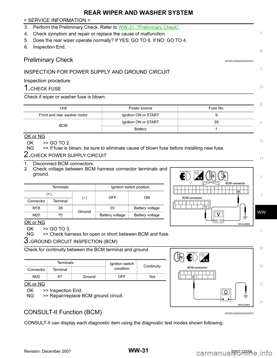
1. Disconnect BCM connectors.
2. Check voltage between BCM harness connector terminals and
ground.
OK or NG
OK >> GO TO 3.
NG >> Check harness for open or short between BCM and fuse.
3.GROUND CIRCUIT INSPECTION (BCM)
Check for continuity between the BCM terminal and ground.
OK or NG
OK >> Inspection End.
NG >> Repair/replace BCM ground circuit.
CONSULT-II Function (BCM)INFOID:0000000003533576
CONSULT-II can display each diagnostic item using the diagnostic test modes shown following.
Unit Power source Fuse No.
Front and rear washer motor Ignition ON or START 9
BCMIgnition ON or START 59
Battery f
Terminals Ignition switch position
(+)
(–) OFF ON
Connector Terminal
M18 38
Ground0V Battery voltage
M20 70 Battery voltage Battery voltage
WKIA2089E
Te r m i n a l s
Ignition switch
conditionContinuity
Connector Terminal
M20 67 Ground OFF Yes
WKIA2090E