2007 INFINITI QX56 transmission oil
[x] Cancel search: transmission oilPage 361 of 3061

ASSEMBLY
AT-291
< SERVICE INFORMATION >
D
E
F
G
H
I
J
K
L
MA
B
AT
N
O
P
2. Measure dimensions “M1 ” and “M2 ” and then calculate dimen-
sion “M”.
a. Place bearing race and needle bearing on oil pump assembly.
b. Measure dimension “M
1 ”.
c. Measure dimension “M
2 ”.
d. Calculate dimension “M”.
SCIA3125E
SCIA3124E
SCIA3126E
SCIA3127E
“M”: Distance between transmission case fitting sur-
face of oil pump and needle bearing on oil pump.
M = M
1 – M2
SCIA3125E
Page 362 of 3061

AT-292
< SERVICE INFORMATION >
ASSEMBLY
3. Adjust total end play “T1 ”.
• Select proper thickness of bearing race so that total end play
is within specifications.
Assembly (2)INFOID:0000000003532495
1. Install new O-ring to oil pump assembly.
CAUTION:
• Do not reuse O-ring.
• Apply ATF to O-ring.
2. Install bearing race to oil pump assembly.
CAUTION:
Apply petroleum jelly to bearing race.
3. Install oil pump assembly in transmission case.
CAUTION:
Apply ATF to oil pump radial bearing.T
1 = J – M
Total end play “T
1 ”:
0.25 - 0.55 mm (0.0098 - 0.0217 in)
Bearing races:
Refer to AT-300, "
Total End Play".SCIA2810E
SCIA5172E
SCIA5252E
SCIA2811E
Page 363 of 3061

ASSEMBLY
AT-293
< SERVICE INFORMATION >
D
E
F
G
H
I
J
K
L
MA
B
AT
N
O
P
4. Apply recommended sealant (Genuine RTV Silicone Sealant or
equivalent) to oil pump assembly as shown. Refer to GI-45,
"Recommended Chemical Product and Sealant".
CAUTION:
Completely remove all moisture, oil and old sealant from
the oil pump bolts and oil pump bolt surfaces.
5. Tighten oil pump bolts to specified torque. Refer to AT-228,
"Component".
CAUTION:
Apply ATF to oil pump bushing.
6. Install new O-ring to input clutch assembly.
CAUTION:
• Do not reuse O-ring.
• Apply ATF to O-ring.
7. Install converter housing to transmission case.
CAUTION:
Do not reuse self-sealing bolt (A).
8. Make sure that brake band does not close turbine revolution
sensor hole.
SCIA5321E
SCIA2300E
SCIA5011E
WCIA0624E
SCIA5034E
Page 367 of 3061

ASSEMBLY
AT-297
< SERVICE INFORMATION >
D
E
F
G
H
I
J
K
L
MA
B
AT
N
O
P
17. Install the oil pan and new oil pan gasket. Refer to AT-209, "Oil Pan".
CAUTION:
• Do not reuse the oil pan gasket.
• Completely remove all moisture, oil and old gasket from the oil pan gasket mating surfaces and
holes.
• Always replace the oil pan bolts as they are self-sealing.
• Be sure the oil pan drain plug hole is located to the rear of the transmission assembly.
• Partially install the oil pan bolts in a criss-cross pattern to prevent dislocation of the gasket.
• Be careful not to pinch harnesses.
18. Install drain plug in oil pan with new gasket.
CAUTION:
Do not reuse the drain plug gasket.
19. Install torque converter.
a. Pour ATF into torque converter.
•Approximately 2 liter (2-1/8 US qt, 1-3/4 Imp qt) of fluid is
required for a new torque converter.
•When reusing old torque converter, add the same amount
of fluid as was drained.
b. Install torque converter while aligning notches of torque con-
verter with notches of oil pump.
CAUTION:
Install torque converter while rotating it.
c. Measure distance “A” to check that torque converter is in proper
position.Drain plug : 34 N·m (3.5 kg-m, 25 ft-lb)
SAT428DA
SCIA5010E
Distance “A” : 24.0 mm (0.94 in) or more
SAT017B
Page 1017 of 3061
![INFINITI QX56 2007 Factory Service Manual
DI-6
< SERVICE INFORMATION >
COMBINATION METERS
POWER SUPPLY AND GROUND CIRCUIT
Power is supplied at all times
• through 10A fuse [No.19, located in the fuse block (J/B)]
• to combination meter t INFINITI QX56 2007 Factory Service Manual
DI-6
< SERVICE INFORMATION >
COMBINATION METERS
POWER SUPPLY AND GROUND CIRCUIT
Power is supplied at all times
• through 10A fuse [No.19, located in the fuse block (J/B)]
• to combination meter t](/manual-img/42/57029/w960_57029-1016.png)
DI-6
< SERVICE INFORMATION >
COMBINATION METERS
POWER SUPPLY AND GROUND CIRCUIT
Power is supplied at all times
• through 10A fuse [No.19, located in the fuse block (J/B)]
• to combination meter terminal 8.
With the ignition switch in the ON or START position, power is supplied
• through 10A fuse [No.14, located in the fuse block (J/B)]
• to combination meter terminal 24.
Ground is supplied
• to combination meter terminal 17
• through body grounds M57, M61 and M79.
WATER TEMPERATURE GAUGE
The water temperature gauge indicates the engine coolant temperature.
ECM provides an engine coolant temperature signal to combination meter via CAN communication lines.
ENGINE OIL PRESSURE GAUGE
The engine oil pressure gauge indicates whether the engine oil pressure is low or normal.
The oil pressure gauge is controlled by the IPDM E/R (intelligent power distribution module engine room). Low
oil pressure causes oil pressure switch terminal 1 to provide ground to IPDM E/R terminal 42. The IPDM E/R
then signals the combination meter (unified meter control unit) via CAN communication lines and a low oil
pressure indication is displayed by the oil pressure gauge.
A/T OIL TEMPERATURE GAUGE
The A/T oil temperature gauge indicates the A/T fluid temperature.
TCM (transmission control module) provides an A/T flui d temperature signal to combination meter via CAN
communication lines.
VOLTAGE GAUGE
The voltage gauge indicates the battery/charging system voltage.
The voltage gauge is regulated by the unified meter control unit.
TA C H O M E T E R
The tachometer indicates engine speed in revolutions per minute (rpm).
ECM provides an engine speed signal to combination meter via CAN communication lines.
FUEL GAUGE
The fuel gauge indicates the approximate fuel level in the fuel tank.
The fuel gauge is regulated by the unified meter control unit and a variable resistor signal supplied
• to combination meter terminal 15.
• through fuel level sensor unit and fuel pump terminal 2
• through fuel level sensor unit and fuel pump terminal 5
• from combination meter terminal 16
SPEEDOMETER
ABS actuator and electric unit (contro l unit) provides a vehicle speed signal to the combination meter via CAN
communication lines.
ODO/TRIP METER
The vehicle speed signal and the memory signals from the meter memory circuit are processed by the combi-
nation meter and the mileage is displayed.
How to Change the Display
Refer to Owner's Manual for odo/tr ip meter operating instructions.
CAN COMMUNICATION SYSTEM DESCRIPTION
Refer to LAN-4.
Page 1832 of 3061

EM-62
< SERVICE INFORMATION >
OIL SEAL
3. Remove the front oil seal using suitable tool.CAUTION:
Do not damage front cover and oil pump drive spacer.
INSTALLATION
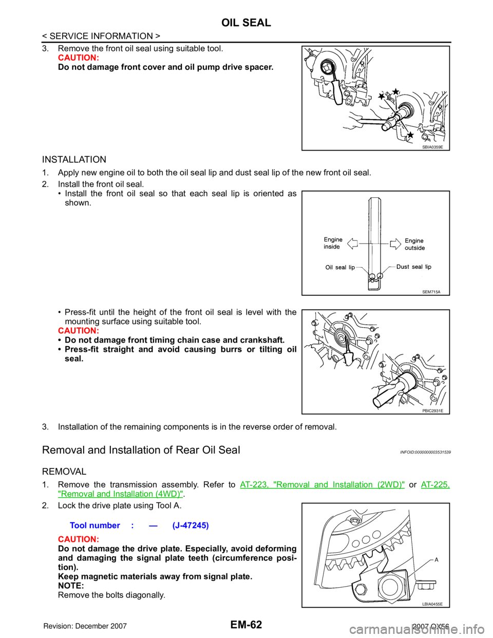
1. Apply new engine oil to both the oil seal lip and dust seal lip of the new front oil seal.
2. Install the front oil seal.• Install the front oil seal so that each seal lip is oriented as
shown.
• Press-fit until the height of the front oil seal is level with the mounting surface using suitable tool.
CAUTION:
• Do not damage front timing chain case and crankshaft.
• Press-fit straight and avoid causing burrs or tilting oil
seal.
3. Installation of the remaining components is in the reverse order of removal.
Removal and Installation of Rear Oil SealINFOID:0000000003531539
REMOVAL
1. Remove the transmission assembly. Refer to AT-223, "Removal and Installation (2WD)" or AT-225,
"Removal and Installation (4WD)".
2. Lock the drive plate using Tool A.
CAUTION:
Do not damage the drive plat e. Especially, avoid deforming
and damaging the signal plat e teeth (circumference posi-
tion).
Keep magnetic materials away from signal plate.
NOTE:
Remove the bolts diagonally.
SBIA0359E
SEM715A
PBIC2931E
Tool number : — (J-47245)
LBIA0455E
Page 1845 of 3061

ENGINE ASSEMBLY
EM-75
< SERVICE INFORMATION >
C
D
E
F
G
H
I
J
K
L
MA
EM
N
P O
6. Remove the engine room cover using power tools.
7. Remove the air duct and air cleaner case assembly. Refer to EM-15, "
Removal and Installation".
8. Disconnect the vacuum hose between the vehicle and engine and set it aside.
9. Remove the radiator assembly and hoses. Refer to CO-13, "
Removal and Installation".
10. Remove the drive belts. Refer to EM-15, "
Removal and Installation".
11. Remove the fan blade. Refer to CO-16, "
Removal and Installation (Crankshaft Driven Type)".
12. Disconnect the engine room harness from the fuse box and set it aside.
13. Disconnect the ECM.
14. Disconnect the engine room harness from the engine side and set it aside.
15. Disconnect the engine harness grounds.
16. Disconnect the power steering reservoir tank from the engine and move it aside.
17. Disconnect the power steering oil pump from the engine. Move it aside and secure it using suitable wire or
rope. Refer to PS-21, "
Removal and Installation".
18. Remove the A/C compressor bolts and set the compressor aside. Refer to ATC-154, "
Removal and Instal-
lation for Compressor" (ATC).
19. Disconnect the brake booster vacuum line.
20. Disconnect the EVAP line.
21. Disconnect the fuel hose at the engine side connection. Refer to EM-31, "
Removal and Installation".
22. Disconnect the heater hoses at the cowl, and install plugs to avoid leakage of engine coolant.
23. Remove the A/T oil level indicator and indicator tube upper bolts.
24. Remove the front final drive assembly (4WD only). Refer to FFD-12, "
Removal and Installation".
25. Remove the exhaust manifolds. Refer to EM-21, "
Removal and Installation".
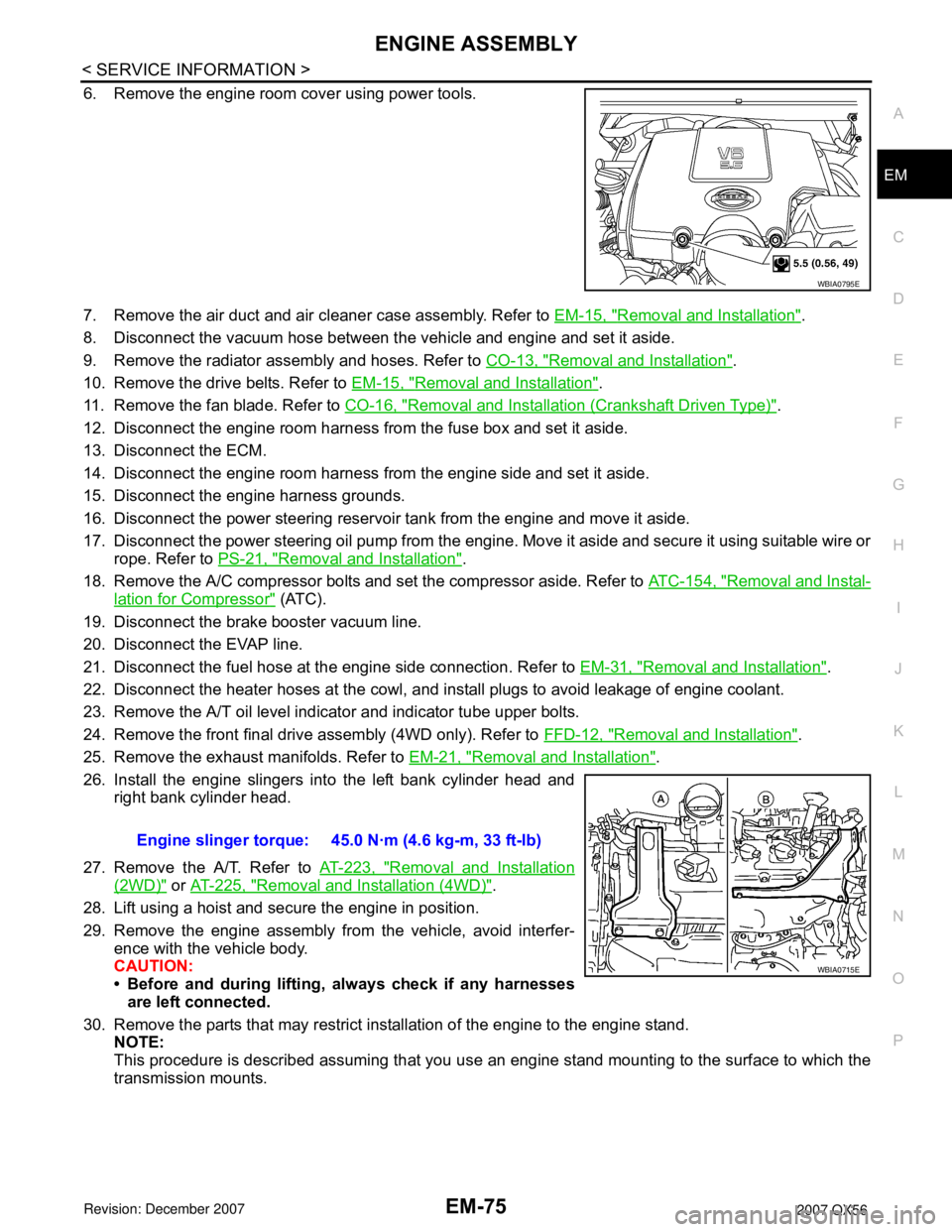
26. Install the engine slingers into the left bank cylinder head and
right bank cylinder head.
27. Remove the A/T. Refer to AT-223, "
Removal and Installation
(2WD)" or AT-225, "Removal and Installation (4WD)".
28. Lift using a hoist and secure the engine in position.
29. Remove the engine assembly from the vehicle, avoid interfer-
ence with the vehicle body.
CAUTION:
• Before and during lifting, always check if any harnesses
are left connected.
30. Remove the parts that may restrict installation of the engine to the engine stand.
NOTE:
This procedure is described assuming that you use an engine stand mounting to the surface to which the
transmission mounts.
WBIA0795E
Engine slinger torque: 45.0 N·m (4.6 kg-m, 33 ft-lb)
WBIA0715E
Page 1846 of 3061

EM-76
< SERVICE INFORMATION >
ENGINE ASSEMBLY
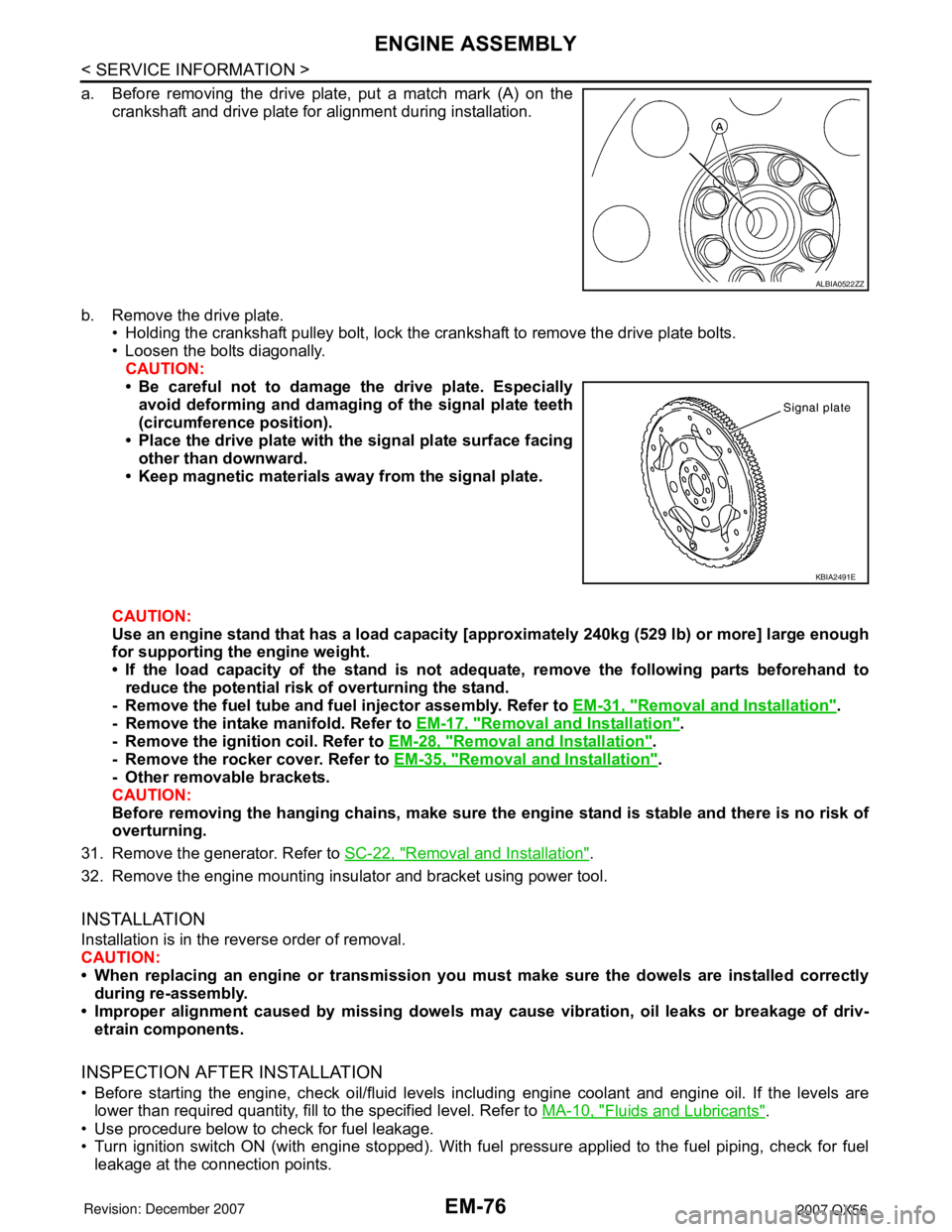
a. Before removing the drive plate, put a match mark (A) on the
crankshaft and drive plate for alignment during installation.
b. Remove the drive plate.
• Holding the crankshaft pulley bolt, lock the crankshaft to remove the drive plate bolts.
• Loosen the bolts diagonally.
CAUTION:
• Be careful not to damage the drive plate. Especially
avoid deforming and damaging of the signal plate teeth
(circumference position).
• Place the drive plate with the signal plate surface facing
other than downward.
• Keep magnetic materials away from the signal plate.
CAUTION:
Use an engine stand that has a load capacity [approximately 240kg (529 lb) or more] large enough
for supporting the engine weight.
• If the load capacity of the stand is not adequate, remove the following parts beforehand to
reduce the potential risk of overturning the stand.
- Remove the fuel tube and fuel injector assembly. Refer to EM-31, "
Removal and Installation".
- Remove the intake manifold. Refer to EM-17, "
Removal and Installation".
- Remove the ignition coil. Refer to EM-28, "
Removal and Installation".
- Remove the rocker cover. Refer to EM-35, "
Removal and Installation".
- Other removable brackets.
CAUTION:
Before removing the hanging chains, make sure the engine stand is stable and there is no risk of
overturning.
31. Remove the generator. Refer to SC-22, "
Removal and Installation".
32. Remove the engine mounting insulator and bracket using power tool.
INSTALLATION
Installation is in the reverse order of removal.
CAUTION:
• When replacing an engine or transmission you must make sure the dowels are installed correctly
during re-assembly.
• Improper alignment caused by missing dowels may cause vibration, oil leaks or breakage of driv-
etrain components.
INSPECTION AFTER INSTALLATION
• Before starting the engine, check oil/fluid levels including engine coolant and engine oil. If the levels are
lower than required quantity, fill to the specified level. Refer to MA-10, "
Fluids and Lubricants".
• Use procedure below to check for fuel leakage.
• Turn ignition switch ON (with engine stopped). With fuel pressure applied to the fuel piping, check for fuel
leakage at the connection points.
ALBIA0522ZZ
KBIA2491E