Page 1201 of 3061
![INFINITI QX56 2007 Factory Service Manual EC-118
< SERVICE INFORMATION >
TROUBLE DIAGNOSIS
A/F S1 HTR (B1)
[%]• A/F sensor 1 heater control value com-
puted by ECM according to the input sig-
nals.
• The current flow to the heater become INFINITI QX56 2007 Factory Service Manual EC-118
< SERVICE INFORMATION >
TROUBLE DIAGNOSIS
A/F S1 HTR (B1)
[%]• A/F sensor 1 heater control value com-
puted by ECM according to the input sig-
nals.
• The current flow to the heater become](/manual-img/42/57029/w960_57029-1200.png)
EC-118
< SERVICE INFORMATION >
TROUBLE DIAGNOSIS
A/F S1 HTR (B1)
[%]• A/F sensor 1 heater control value com-
puted by ECM according to the input sig-
nals.
• The current flow to the heater becomes
larger as the value increases. A/F S1 HTR (B2)
[%]
AC PRESS SEN [V]• The signal voltage from the refrigerant
pressure sensor is displayed.
VHCL SPEED SE
[km/h] or [mph]• The vehicle speed computed from the
vehicle speed signal sent from combina-
tion meter is displayed.
SET VHCL SPD
[km/h] or [mph]• The preset vehicle speed is displayed.
MAIN SW
[ON/OFF]• Indicates [ON/OFF] condition from MAIN
switch signal.
CANCEL SW
[ON/OFF]• Indicates [ON/OFF] condition from CAN-
CEL switch signal.
RESUME/ACC SW
[ON/OFF]• Indicates [ON/OFF] condition from RE-
SUME/ACCELERATE switch signal.
SET SW
[ON/OFF]• Indicates [ON/OFF] condition from SET/
COAST switch signal.
BRAKE SW1
[ON/OFF]• Indicates [ON/OFF] condition from
ASCD brake switch signal.
BRAKE SW2
[ON/OFF]• Indicates [ON/OFF] condition of stop
lamp switch signal.
DIST SW
[ON/OFF]• Indicates [ON/OFF] condition from DIS-
TANCE switch signal.
VHCL SPD CUT
[NON/CUT]• Indicates the vehicle cruise condition.
NON: Vehicle speed is maintained at the
ASCD set speed.
CUT: Vehicle speed increased to exces-
sively high compared with the ASCD set
speed, and ASCD operation is cut off.
LO SPEED CUT
[NON/CUT]• Indicates the vehicle cruise condition.
NON: Vehicle speed is maintained at the
ASCD set speed.
CUT: Vehicle speed decreased to exces-
sively low compared with the ASCD set
speed, and ASCD operation is cut off.
AT O D M O N I T O R
[ON/OFF]• Indicates [ON/OFF] condition of A/T O/D
according to the input signal from the
TCM.
AT O D C A N C E L
[ON/OFF]• Indicates [ON/OFF] condition of A/T O/D
cancel signal sent from the TCM.
CRUISE LAMP
[ON/OFF]• Indicates [ON/OFF] condition of CRUISE
lamp determined by the ECM according
to the input signals.
SET LAMP
[ON/OFF]• Indicates [ON/OFF] condition of SET
lamp determined by the ECM according
to the input signals.
ALT DUTY [%]• Indicates the duty ratio of the power gen-
eration command value. The ratio is cal-
culated by ECM based on the battery
current sensor signal.
BAT CUR SEN [mV]• The signal voltage of battery current sen-
sor is displayed. Monitored item
[Unit]ECM IN-
PUT SIG-
NALSMAIN
SIGNALSDescription Remarks
Page 1208 of 3061

TROUBLE DIAGNOSIS
EC-125
< SERVICE INFORMATION >
C
D
E
F
G
H
I
J
K
L
MA
EC
N
P O
AIR COND SIG• Engine: After warming up, idle the
engineAir conditioner switch: OFF OFF
Air conditioner switch: ON
(Compressor operates.)ON
P/N POSI SW • Ignition switch: ONSelector lever: P or N ON
Selector lever: Except above OFF
PW/ST SIGNAL• Engine: After warming up, idle the
engineSteering wheel: Not being turned
(Forward direction)OFF
Steering wheel: Being turned ON
LOAD SIGNAL • Ignition switch: ONRear window defogger switch is ON
and/or lighting switch is in 2nd.ON
Rear window defogger switch is OFF
and lighting switch is OFF.OFF
IGNITION SW • Ignition switch: ON → OFF → ON ON → OFF → ON
HEATER FAN SW• Engine: After warming up, idle the
engineHeater fan control switch: ON ON
Heater fan control switch: OFF OFF
BRAKE SW • Ignition switch: ONBrake pedal: Fully released OFF
Brake pedal: Slightly depressed ON
INJ PULSE-B1
INJ PULSE-B2• Engine: After warming up
• Selector lever: P or N
• Air conditioner switch: OFF
• No loadIdle 2.0 - 2.8 msec
2,000 rpm 1.9 - 2.9 msec
IGN TIMING• Engine: After warming up
• Selector lever: P or N
• Air conditioner switch: OFF
• No loadIdle 10° - 20° BTDC
2,000 rpm 25° - 45° BTDC
CAL/LD VALUE• Engine: After warming up
• Selector lever: P or N
• Air conditioner switch: OFF
• No loadIdle 14% - 33%
2,500 rpm 12% - 25%
MASS AIRFLOW• Engine: After warming up
• Selector lever: P or N
• Air conditioner switch: OFF
• No loadIdle 3.0 - 9.0 g·m/s
2,500 rpm 9.0 - 28.0 g·m/s
PURG VOL C/V• Engine: After warming up
• Selector lever: P or N
• Air conditioner switch: OFF
• No loadIdle
(Accelerator pedal: Not depressed
even slightly, after engine starting.)0%
2,000 rpm —
INT/V TIM (B1)
INT/V TIM (B2)• Engine: After warming up
• Selector lever: P or N
• Air conditioner switch: OFF
• No loadIdle−5° - 5°CA
2,000 rpm Approx. 0° - 20°CA
INT/V SOL (B1)
INT/V SOL (B2)• Engine: After warming up
• Selector lever: P or N
• Air conditioner switch: OFF
• No loadIdle 0% - 2%
2,000 rpm Approx. 25% - 50%
AIR COND RLY• Engine: After warming up, idle the
engineAir conditioner switch: OFF OFF
Air conditioner switch: ON
(Compressor: Operates)ON
FUEL PUMP RLY• For 1 second after turning ignition switch ON
• Engine running or crankingON
• Except above conditions OFF
VENT CONT/V • Ignition switch: ON OFF
THRTL RELAY • Ignition switch: ON ONMONITOR ITEM CONDITION SPECIFICATION
Page 1246 of 3061

DTC P0031, P0032, P0051, P0052 A/F SENSOR 1 HEATER
EC-163
< SERVICE INFORMATION >
C
D
E
F
G
H
I
J
K
L
MA
EC
N
P O
DTC P0031, P0032, P0051, P0052 A/F SENSOR 1 HEATER
DescriptionINFOID:0000000003531656
SYSTEM DESCRIPTION
The ECM performs ON/OFF duty control of the A/F sensor 1 heater corresponding to the engine operating
condition to keep the temperature of A/F sensor 1 element at the specified range.
CONSULT-II Reference Value in Data Monitor ModeINFOID:0000000003531657
Specification data are reference values.
On Board Diagnosis LogicINFOID:0000000003531658
DTC Confirmation ProcedureINFOID:0000000003531659
NOTE:
If DTC Confirmation Procedure has been previously conducted, always turn ignition switch OFF and wait at
least 10 seconds before conducting the next test.
TESTING CONDITION:
Before performing the following procedure, confirm that battery voltage is between 10.5V and 16V at
idle.
WITH CONSULT-II
1. Turn ignition switch ON and select “DATA MONITOR” mode with
CONSULT-II.
2. Start engine and let it idle for at least 10 seconds.
3. If 1st trip DTC is detected, go to EC-167, "
Diagnosis Procedure".
Sensor Input Signal to ECM ECM function Actuator
Camshaft position sensor (PHASE)
Crankshaft position sensor (POS)Engine speed
Air fuel ratio (A/F) sensor 1
heater controlAir fuel ratio (A/F) sensor 1
heater
Mass air flow sensor Amount of intake air
MONITOR ITEM CONDITION SPECIFICATION
A/F S1 HTR (B1)
A/F S1 HTR (B2)• Engine: After warming up, idle the engine 4 - 100%
DTC No. Trouble diagnosis name DTC detecting condition Possible cause
P0031
0031
(Bank 1)
Air fuel ratio (A/F) sensor
1 heater control circuit lowThe current amperage in the air fuel ratio (A/F) sen-
sor 1 heater circuit is out of the normal range.
(An excessively low voltage signal is sent to ECM
through the air fuel ratio (A/F) sensor 1 heater.)• Harness or connectors
(The A/F sensor 1 heater circuit is
open or shorted.)
• A/F sensor 1 heater P0051
0051
(Bank 2)
P0032
0032
(Bank 1)Air fuel ratio (A/F) sensor
1 heater control circuit
highThe current amperage in the air fuel ratio (A/F) sen-
sor 1 heater circuit is out of the normal range.
(An excessively high voltage signal is sent to ECM
through the air fuel ratio (A/F) sensor 1 heater.)• Harness or connectors
(The A/F sensor 1 heater circuit is
shorted.)
• A/F sensor 1 heater P0052
0052
(Bank 2)
SEF058Y
Page 1247 of 3061
EC-164
< SERVICE INFORMATION >
DTC P0031, P0032, P0051, P0052 A/F SENSOR 1 HEATER
WITH GST
Follow the procedure “WITH CONSULT-II” above.
Wiring DiagramINFOID:0000000003531660
BANK 1
Specification data are reference values and are measured between each terminal and ground.
BBWA2788E
Page 1248 of 3061
DTC P0031, P0032, P0051, P0052 A/F SENSOR 1 HEATER
EC-165
< SERVICE INFORMATION >
C
D
E
F
G
H
I
J
K
L
MA
EC
N
P O
Pulse signal is measured by CONSULT-II.
CAUTION:
Do not use ECM ground terminals when measuring input/output voltage. Doing so may result in dam-
age to the ECM's transistor. Use a ground other than ECM terminals, such as the ground.
: Average voltage for pulse signal (Actual pulse signal can be confirmed by oscilloscope.)TER-
MI-
NAL
NO.WIRE
COLORITEM CONDITION DATA (DC Voltage)
2 LG/B A/F sensor 1 heater (bank 1)[Engine is running]
•Warm-up condition
• Idle speed
(More than 140 seconds after starting en-
gine)Approximately 2.9 - 8.8V
35 BR/R A/F sensor 1 (bank 1)[Engine is running]
•Warm-up condition
• Engine speed: 2,000 rpmApproximately 1.8V
Output voltage varies with air fuel
ratio.
56 BR/G A/F sensor 1 (bank 1)[Ignition switch: ON]Approximately 2.2V
PBIA8148J
Page 1249 of 3061
EC-166
< SERVICE INFORMATION >
DTC P0031, P0032, P0051, P0052 A/F SENSOR 1 HEATER
BANK 2
Specification data are reference values and are measured between each terminal and ground.
Pulse signal is measured by CONSULT-II.
CAUTION:
Do not use ECM ground terminals when measuring input/output voltage. Doing so may result in dam-
age to the ECM's transistor. Use a ground other than ECM terminals, such as the ground.
BBWA2789E
Page 1250 of 3061

DTC P0031, P0032, P0051, P0052 A/F SENSOR 1 HEATER
EC-167
< SERVICE INFORMATION >
C
D
E
F
G
H
I
J
K
L
MA
EC
N
P O
: Average voltage for pulse signal (Actual pulse signal can be confirmed by oscilloscope.)
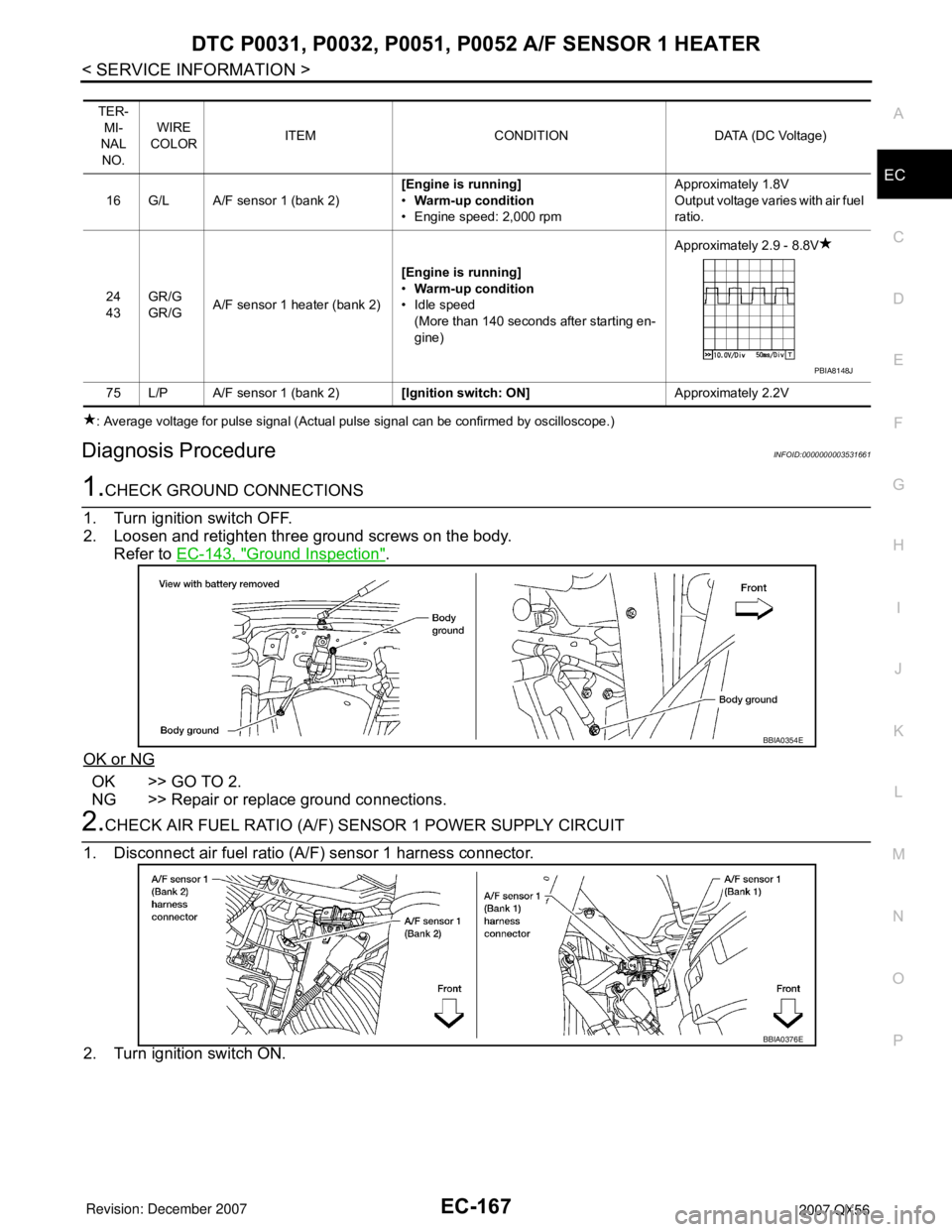
Diagnosis ProcedureINFOID:0000000003531661
1.CHECK GROUND CONNECTIONS
1. Turn ignition switch OFF.
2. Loosen and retighten three ground screws on the body.
Refer to EC-143, "
Ground Inspection".
OK or NG
OK >> GO TO 2.
NG >> Repair or replace ground connections.
2.CHECK AIR FUEL RATIO (A/F) SENSOR 1 POWER SUPPLY CIRCUIT
1. Disconnect air fuel ratio (A/F) sensor 1 harness connector.
2. Turn ignition switch ON.
TER-
MI-
NAL
NO.WIRE
COLORITEM CONDITION DATA (DC Voltage)
16 G/L A/F sensor 1 (bank 2)[Engine is running]
•Warm-up condition
• Engine speed: 2,000 rpmApproximately 1.8V
Output voltage varies with air fuel
ratio.
24
43GR/G
GR/GA/F sensor 1 heater (bank 2)[Engine is running]
•Warm-up condition
• Idle speed
(More than 140 seconds after starting en-
gine)Approximately 2.9 - 8.8V
75 L/P A/F sensor 1 (bank 2)[Ignition switch: ON]Approximately 2.2V
PBIA8148J
BBIA0354E
BBIA0376E
Page 1251 of 3061

EC-168
< SERVICE INFORMATION >
DTC P0031, P0032, P0051, P0052 A/F SENSOR 1 HEATER
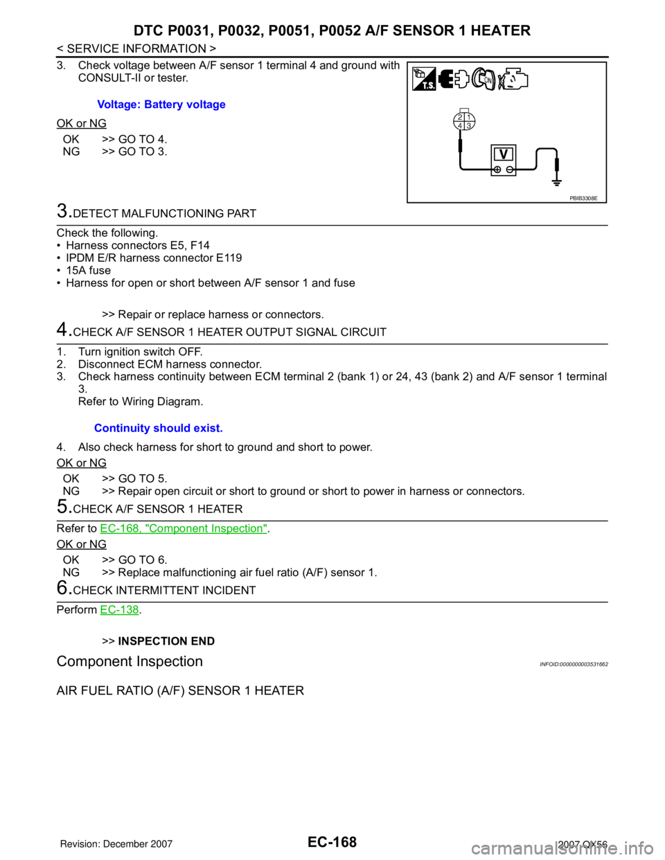
3. Check voltage between A/F sensor 1 terminal 4 and ground with
CONSULT-II or tester.
OK or NG
OK >> GO TO 4.
NG >> GO TO 3.
3.DETECT MALFUNCTIONING PART
Check the following.
• Harness connectors E5, F14
• IPDM E/R harness connector E119
• 15A fuse
• Harness for open or short between A/F sensor 1 and fuse
>> Repair or replace harness or connectors.
4.CHECK A/F SENSOR 1 HEATER OUTPUT SIGNAL CIRCUIT
1. Turn ignition switch OFF.
2. Disconnect ECM harness connector.
3. Check harness continuity between ECM terminal 2 (bank 1) or 24, 43 (bank 2) and A/F sensor 1 terminal
3.
Refer to Wiring Diagram.
4. Also check harness for short to ground and short to power.
OK or NG
OK >> GO TO 5.
NG >> Repair open circuit or short to ground or short to power in harness or connectors.
5.CHECK A/F SENSOR 1 HEATER
Refer to EC-168, "
Component Inspection".
OK or NG
OK >> GO TO 6.
NG >> Replace malfunctioning air fuel ratio (A/F) sensor 1.
6.CHECK INTERMITTENT INCIDENT
Perform EC-138
.
>>INSPECTION END
Component InspectionINFOID:0000000003531662
AIR FUEL RATIO (A/F) SENSOR 1 HEATER
Voltage: Battery voltage
PBIB3308E
Continuity should exist.