Page 1357 of 3061
EC-274
< SERVICE INFORMATION >
DTC P0138, P0158 HO2S2
TER-
MI-
NAL
NO.WIRE
COLORITEM CONDITION DATA (DC Voltage)
6GRHeated oxygen sensor 2
heater (bank 1)[Engine is running]
• Engine speed: Below 3,600 rpm after the fol-
lowing conditions are met.
- Engine: After warming up
- Keeping the engine speed between 3,500
and 4,000 rpm for 1 minute and at idle for 1
minute under no load0 - 1.0V
[Ignition switch: ON]
• Engine: Stopped
[Engine is running]
• Engine speed: Above 3,600 rpm.BATTERY VOLTAGE
(11 - 14V)
55 RHeated oxygen sensor 2
(bank 1)[Engine is running]
• Revving engine from idle to 3,000 rpm quick-
ly after the following conditions are met.
- Engine: After warming up
- Keeping the engine speed between 3,500
and 4,000 rpm for 1 minute and at idle for 1
minute under no load0 - Approximately 1.0V
78 B/WSensor ground
(Heated oxygen sensor 2) [Engine is running]
•Warm-up condition
• Idle speed Approximately 0V
Page 1359 of 3061
EC-276
< SERVICE INFORMATION >
DTC P0138, P0158 HO2S2
Diagnosis Procedure
INFOID:0000000003531780
PROCEDURE FOR MALFUNCTION A
1.CHECK GROUND CONNECTIONS
1. Turn ignition switch OFF.
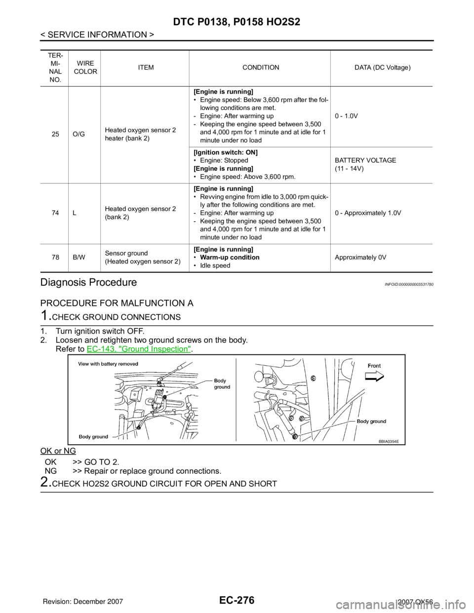
2. Loosen and retighten two ground screws on the body.
Refer to EC-143, "
Ground Inspection".
OK or NG
OK >> GO TO 2.
NG >> Repair or replace ground connections.
2.CHECK HO2S2 GROUND CIRCUIT FOR OPEN AND SHORT
TER-
MI-
NAL
NO.WIRE
COLORITEM CONDITION DATA (DC Voltage)
25 O/GHeated oxygen sensor 2
heater (bank 2)[Engine is running]
• Engine speed: Below 3,600 rpm after the fol-
lowing conditions are met.
- Engine: After warming up
- Keeping the engine speed between 3,500
and 4,000 rpm for 1 minute and at idle for 1
minute under no load0 - 1.0V
[Ignition switch: ON]
• Engine: Stopped
[Engine is running]
• Engine speed: Above 3,600 rpm.BATTERY VOLTAGE
(11 - 14V)
74 LHeated oxygen sensor 2
(bank 2)[Engine is running]
• Revving engine from idle to 3,000 rpm quick-
ly after the following conditions are met.
- Engine: After warming up
- Keeping the engine speed between 3,500
and 4,000 rpm for 1 minute and at idle for 1
minute under no load0 - Approximately 1.0V
78 B/WSensor ground
(Heated oxygen sensor 2) [Engine is running]
•Warm-up condition
• Idle speed Approximately 0V
BBIA0354E
Page 1368 of 3061

DTC P0139, P0159 HO2S2
EC-285
< SERVICE INFORMATION >
C
D
E
F
G
H
I
J
K
L
MA
EC
N
P O
Do not use ECM ground terminals when measuring input/output voltage. Doing so may result in dam-
age to the ECM's transistor. Use a ground other than ECM terminals, such as the ground.
TER-
MI-
NAL
NO.WIRE
COLORITEM CONDITION DATA (DC Voltage)
6GRHeated oxygen sensor 2
heater (bank 1)[Engine is running]
• Engine speed: Below 3,600 rpm after the fol-
lowing conditions are met.
- Engine: After warming up
- Keeping the engine speed between 3,500
and 4,000 rpm for 1 minute and at idle for 1
minute under no load0 - 1.0V
[Ignition switch: ON]
• Engine: Stopped
[Engine is running]
• Engine speed: Above 3,600 rpm.BATTERY VOLTAGE
(11 - 14V)
55 RHeated oxygen sensor 2
(bank 1)[Engine is running]
• Revving engine from idle to 3,000 rpm quick-
ly after the following conditions are met.
- Engine: After warming up
- Keeping the engine speed between 3,500
and 4,000 rpm for 1 minute and at idle for 1
minute under no load0 - Approximately 1.0V
78 B/WSensor ground
(Heated oxygen sensor 2) [Engine is running]
•Warm-up condition
• Idle speed Approximately 0V
Page 1370 of 3061
DTC P0139, P0159 HO2S2
EC-287
< SERVICE INFORMATION >
C
D
E
F
G
H
I
J
K
L
MA
EC
N
P O
Diagnosis ProcedureINFOID:0000000003531789
1.CHECK GROUND CONNECTIONS
1. Turn ignition switch OFF.
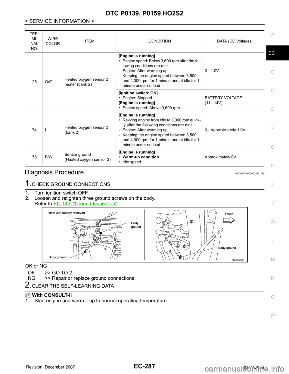
2. Loosen and retighten three ground screws on the body.
Refer to EC-143, "
Ground Inspection".
OK or NG
OK >> GO TO 2.
NG >> Repair or replace ground connections.
2.CLEAR THE SELF-LEARNING DATA
With CONSULT-II
1. Start engine and warm it up to normal operating temperature.
TER-
MI-
NAL
NO.WIRE
COLORITEM CONDITION DATA (DC Voltage)
25 O/GHeated oxygen sensor 2
heater (bank 2)[Engine is running]
• Engine speed: Below 3,600 rpm after the fol-
lowing conditions are met.
- Engine: After warming up
- Keeping the engine speed between 3,500
and 4,000 rpm for 1 minute and at idle for 1
minute under no load0 - 1.0V
[Ignition switch: ON]
• Engine: Stopped
[Engine is running]
• Engine speed: Above 3,600 rpm.BATTERY VOLTAGE
(11 - 14V)
74 LHeated oxygen sensor 2
(bank 2)[Engine is running]
• Revving engine from idle to 3,000 rpm quick-
ly after the following conditions are met.
- Engine: After warming up
- Keeping the engine speed between 3,500
and 4,000 rpm for 1 minute and at idle for 1
minute under no load0 - Approximately 1.0V
78 B/WSensor ground
(Heated oxygen sensor 2) [Engine is running]
•Warm-up condition
• Idle speed Approximately 0V
BBIA0354E
Page 1378 of 3061
DTC P0171, P0174 FUEL INJECTION SYSTEM FUNCTION
EC-295
< SERVICE INFORMATION >
C
D
E
F
G
H
I
J
K
L
MA
EC
N
P O
Do not use ECM ground terminals when measuring input/output voltage. Doing so may result in dam-
age to the ECM's transistor. Use a ground other than ECM terminals, such as the ground.
: Average voltage for pulse signal (Actual pulse signal can be confirmed by oscilloscope.)TER-
MI-
NAL
NO.WIRE
COLORITEM CONDITION DATA (DC Voltage)
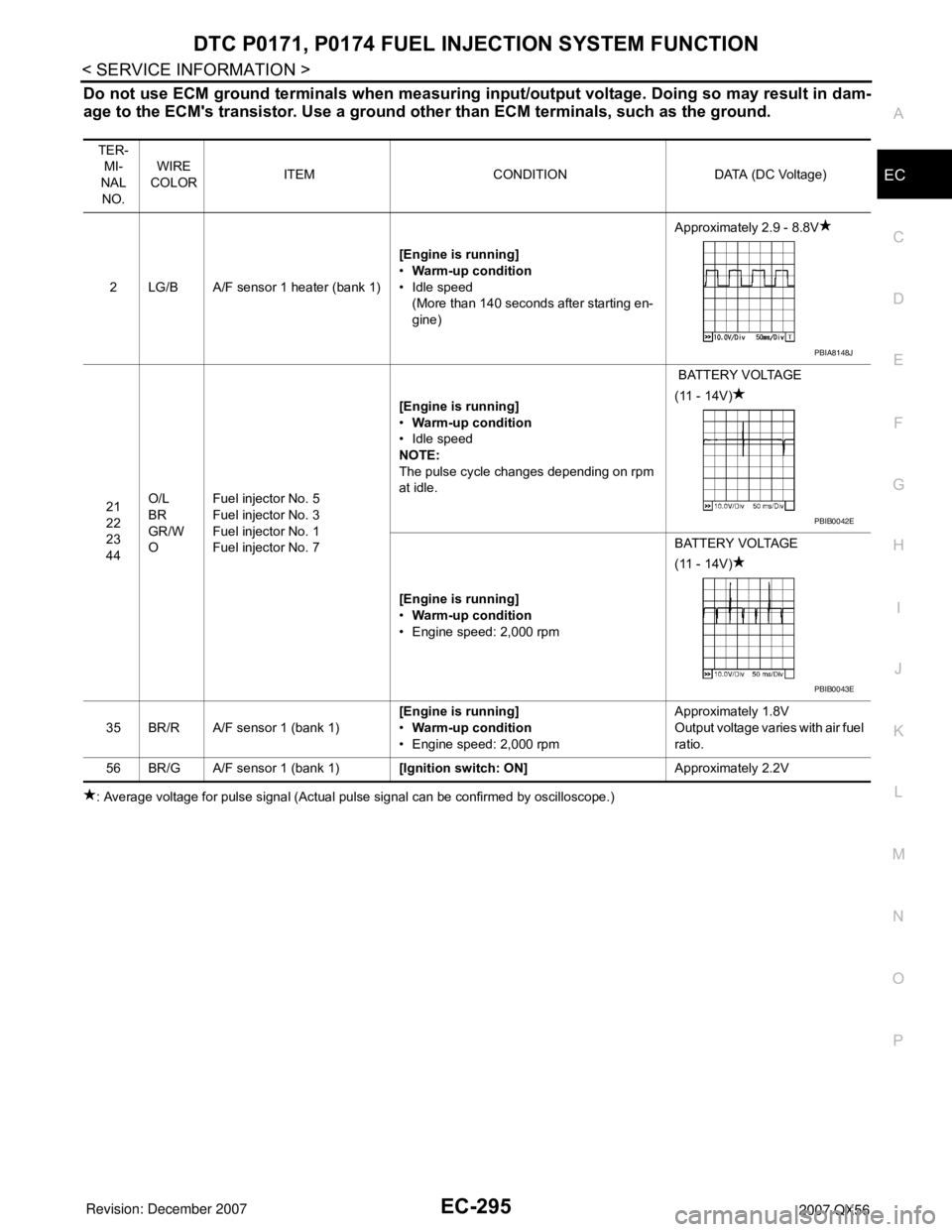
2 LG/B A/F sensor 1 heater (bank 1)[Engine is running]
•Warm-up condition
• Idle speed
(More than 140 seconds after starting en-
gine)Approximately 2.9 - 8.8V
21
22
23
44O/L
BR
GR/W
OFuel injector No. 5
Fuel injector No. 3
Fuel injector No. 1
Fuel injector No. 7[Engine is running]
•Warm-up condition
• Idle speed
NOTE:
The pulse cycle changes depending on rpm
at idle. BATTERY VOLTAGE
(11 - 14V)
[Engine is running]
•Warm-up condition
• Engine speed: 2,000 rpmBATTERY VOLTAGE
(11 - 14V)
35 BR/R A/F sensor 1 (bank 1)[Engine is running]
•Warm-up condition
• Engine speed: 2,000 rpmApproximately 1.8V
Output voltage varies with air fuel
ratio.
56 BR/G A/F sensor 1 (bank 1)[Ignition switch: ON]Approximately 2.2V
PBIA8148J
PBIB0042E
PBIB0043E
Page 1380 of 3061
DTC P0171, P0174 FUEL INJECTION SYSTEM FUNCTION
EC-297
< SERVICE INFORMATION >
C
D
E
F
G
H
I
J
K
L
MA
EC
N
P O
: Average voltage for pulse signal (Actual pulse signal can be confirmed by oscilloscope.)
Diagnosis ProcedureINFOID:0000000003531795
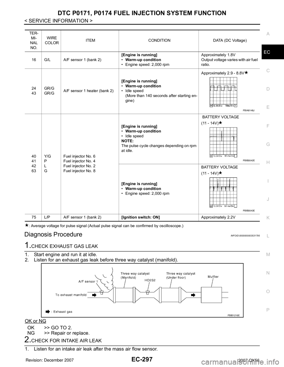
1.CHECK EXHAUST GAS LEAK
1. Start engine and run it at idle.
2. Listen for an exhaust gas leak before three way catalyst (manifold).
OK or NG
OK >> GO TO 2.
NG >> Repair or replace.
2.CHECK FOR INTAKE AIR LEAK
1. Listen for an intake air leak after the mass air flow sensor.
TER-
MI-
NAL
NO.WIRE
COLORITEM CONDITION DATA (DC Voltage)
16 G/L A/F sensor 1 (bank 2)[Engine is running]
•Warm-up condition
• Engine speed: 2,000 rpmApproximately 1.8V
Output voltage varies with air fuel
ratio.
24
43GR/G
GR/GA/F sensor 1 heater (bank 2)[Engine is running]
•Warm-up condition
• Idle speed
(More than 140 seconds after starting en-
gine)Approximately 2.9 - 8.8V
40
41
42
63Y/G
P
L
GFuel injector No. 6
Fuel injector No. 4
Fuel injector No. 2
Fuel injector No. 8[Engine is running]
•Warm-up condition
• Idle speed
NOTE:
The pulse cycle changes depending on rpm
at idle. BATTERY VOLTAGE
(11 - 14V)
[Engine is running]
•Warm-up condition
• Engine speed: 2,000 rpmBATTERY VOLTAGE
(11 - 14V)
75 L/P A/F sensor 1 (bank 2)[Ignition switch: ON]Approximately 2.2V
PBIA8148J
PBIB0042E
PBIB0043E
PBIB1216E
Page 1387 of 3061
EC-304
< SERVICE INFORMATION >
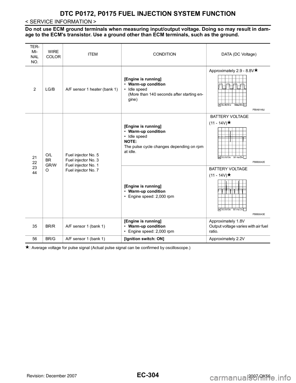
DTC P0172, P0175 FUEL INJECTION SYSTEM FUNCTION
Do not use ECM ground terminals when measuring input/output voltage. Doing so may result in dam-
age to the ECM's transistor. Use a ground other than ECM terminals, such as the ground.
: Average voltage for pulse signal (Actual pulse signal can be confirmed by oscilloscope.)TER-
MI-
NAL
NO.WIRE
COLORITEM CONDITION DATA (DC Voltage)
2 LG/B A/F sensor 1 heater (bank 1)[Engine is running]
•Warm-up condition
• Idle speed
(More than 140 seconds after starting en-
gine)Approximately 2.9 - 8.8V
21
22
23
44O/L
BR
GR/W
OFuel injector No. 5
Fuel injector No. 3
Fuel injector No. 1
Fuel injector No. 7[Engine is running]
•Warm-up condition
• Idle speed
NOTE:
The pulse cycle changes depending on rpm
at idle. BATTERY VOLTAGE
(11 - 14V)
[Engine is running]
•Warm-up condition
• Engine speed: 2,000 rpmBATTERY VOLTAGE
(11 - 14V)
35 BR/R A/F sensor 1 (bank 1)[Engine is running]
•Warm-up condition
• Engine speed: 2,000 rpmApproximately 1.8V
Output voltage varies with air fuel
ratio.
56 BR/G A/F sensor 1 (bank 1)[Ignition switch: ON]Approximately 2.2V
PBIA8148J
PBIB0042E
PBIB0043E
Page 1389 of 3061
EC-306
< SERVICE INFORMATION >
DTC P0172, P0175 FUEL INJECTION SYSTEM FUNCTION
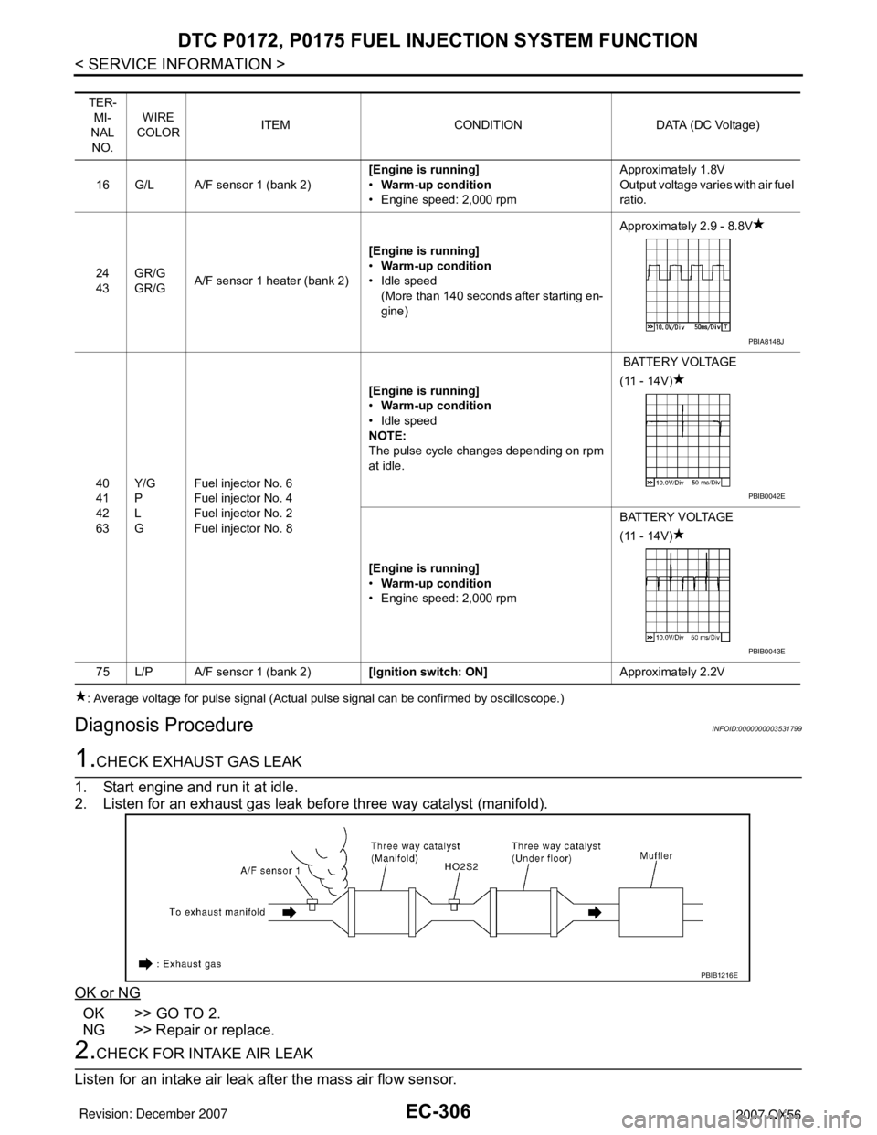
: Average voltage for pulse signal (Actual pulse signal can be confirmed by oscilloscope.)
Diagnosis ProcedureINFOID:0000000003531799
1.CHECK EXHAUST GAS LEAK
1. Start engine and run it at idle.
2. Listen for an exhaust gas leak before three way catalyst (manifold).
OK or NG
OK >> GO TO 2.
NG >> Repair or replace.
2.CHECK FOR INTAKE AIR LEAK
Listen for an intake air leak after the mass air flow sensor.
TER-
MI-
NAL
NO.WIRE
COLORITEM CONDITION DATA (DC Voltage)
16 G/L A/F sensor 1 (bank 2)[Engine is running]
•Warm-up condition
• Engine speed: 2,000 rpmApproximately 1.8V
Output voltage varies with air fuel
ratio.
24
43GR/G
GR/GA/F sensor 1 heater (bank 2)[Engine is running]
•Warm-up condition
• Idle speed
(More than 140 seconds after starting en-
gine)Approximately 2.9 - 8.8V
40
41
42
63Y/G
P
L
GFuel injector No. 6
Fuel injector No. 4
Fuel injector No. 2
Fuel injector No. 8[Engine is running]
•Warm-up condition
• Idle speed
NOTE:
The pulse cycle changes depending on rpm
at idle. BATTERY VOLTAGE
(11 - 14V)
[Engine is running]
•Warm-up condition
• Engine speed: 2,000 rpmBATTERY VOLTAGE
(11 - 14V)
75 L/P A/F sensor 1 (bank 2)[Ignition switch: ON]Approximately 2.2V
PBIA8148J
PBIB0042E
PBIB0043E
PBIB1216E