Page 2382 of 3061
MA-20
< SERVICE INFORMATION >
CHASSIS AND BODY MAINTENANCE
CHASSIS AND BODY MAINTENANCE
Changing In-cabin MicrofilterINFOID:0000000003533875
1. Remove the two lower glove box hinge pins to remove the glove
box from the instrument panel and let it hang from the cord.
2. Remove the screw and remove the in-cabin microfilter cover.
3. Remove the in-cabin microfilters from the front heater and cool-
ing unit assembly housing.
4. Insert the first new in-cabin microfilter into the front heater and
cooling unit assembly housing and slide it over to the right.
Insert the second new in-cabin microfilter into the front heater
and cooling unit assembly housing.
NOTE:
The in-cabin microfilters are marked with air flow arrows. The
end of the microfilter with the arrow should face the rear of the
vehicle. The arrows should point downward.
5. Install the in-cabin microfilter cover.
WLIA0027E
LJIA0134E
LJIA0148E
LJIA0134E
Page 2463 of 3061

HARNESS
PG-61
< SERVICE INFORMATION >
C
D
E
F
G
H
I
J
L
MA
B
PG
N
O
P
ICC/BS EC ICC Steering Switch
ICC/SW EC ICC Brake Switch
I/MIRR GW Inside Mirror (Auto Anti-Dazzling Mirror)
IATS EC Intake Air Temperature Sensor
IGNSYS EC Ignition System
ILL LT Illumination
INJECT EC Injector
INT/L LT Room/Map, Vanity, Cargo, Personal, Foot, Step, and Puddle Lamps
KEYLES BL Remote Keyless Entry System
KS EC Knock Sensor
MAFS EC Mass Air Flow Sensor
MAIN EC Main Power Supply and Ground Circuit
METER DI Speedometer, Tachometer, Temp. and Fuel Gauges
MIL/DL EC Malfunction Indicator Lamp
MIRROR GW Door Mirror
NATS BL Nissan Anti-Theft System
NAVI AV Navigation System
O2H2B1 EC Rear Heated Oxygen Sensor 2 Heater Bank 1
O2H2B2 EC Rear Heated Oxygen Sensor 2 Heater Bank 2
O2S2B1 EC Heated Oxygen Sensor 2 Bank 1
O2S2B2 EC Heated Oxygen Sensor 2 Bank 2
P/SCKT WW Power Socket
PGC/V EC EVAP Canister Purge Volume Control Solenoid Valve
PHASE EC Camshaft Position Sensor (PHASE) (Bank 1)
PNP/SW EC Park/Neutral Position Switch
POS EC Crankshaft Position Sensor (POS)
POWER PG Power Supply Routing
PRE/SE EC EVAP Control System Pressure Sensor
PS/SEN EC Power Steering Pressure Sensor
R/VIEW DI Rear View Monitor
RP/SEN EC Refrigerant Pressure Sensor
SEN/PW EC Sensor Power Supply
SHIFT AT A/T Shift Lock System
SONAR DI Rear Sonar System
SROOF RF Sunroof
SRS SRS Supplemental Restraint System
START SC Starting System
STOP/L LT Stop Lamp
T/TOW LT Trailer Tow
T/WARN WT Low Tire Pressure Warning System
TAIL/L LT Parking, License and Tail Lamps
T/F TF Transfer Case
TPS1 EC Throttle Position Sensor
TPS2 EC Throttle Position Sensor
TPS3 EC Throttle Position Sensor
TRNSCV BL HOMELINK® Universal Transceiver
TURN LT Turn Signal and Hazard Warning Lamps
VDC BRC Vehicle Dynamic Control System
VEHSEC BL Vehicle security (theft warning) system
VENT/V EC EVAP Canister Vent Control Valve
W/ANT AV Audio Antenna
WARN DI Warning Lamps
Page 2666 of 3061

SC-18
< SERVICE INFORMATION >
CHARGING SYSTEM
Before starting, perform the preliminary inspection. Refer to "PRELIMINARY INSPECTION".
1. Stop the operation of the power generation variable voltage control system using either of the following
procedures.
• Using the CONSULT-II, select "ENGINE" from "SELECT SYSTEM" and set the "ALT DUTY" to 0%.
Keep "ALT DUTY" at 0% until the end of the inspection. When the "ALT DUTY" value is 0% or 100%,
normal power generation is performed according to the characteristic of the IC regulator in the genera-
tor.
• Turn the ignition switch off, and disconnect the battery current sensor connector. Disconnecting the bat-
tery current sensor may cause DTC (P1550 - P1554) to set. After finishing the inspection, connect the
battery current sensor connector and erase the self-diagnostic results history of the engine using CON-
SULT-II.
2. Turn off all loads on the vehicle electrical system.
3. Perform battery and starting system test with Battery/Starting/
Charging system tester.
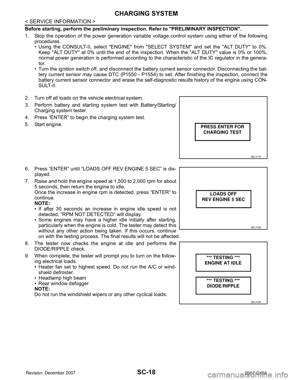
4. Press “ENTER” to begin the charging system test.
5. Start engine.
6. Press “ENTER” until “LOADS OFF REV ENGINE 5 SEC” is dis-
played.
7. Raise and hold the engine speed at 1,500 to 2,000 rpm for about
5 seconds, then return the engine to idle.
Once the increase in engine rpm is detected, press “ENTER” to
continue.
NOTE:
• If after 30 seconds an increase in engine idle speed is not
detected, “RPM NOT DETECTED” will display.
• Some engines may have a higher idle initially after starting,
particularly when the engine is cold. The tester may detect this
without any other action being taken. If this occurs, continue
on with the testing process. The final results will not be affected.
8. The tester now checks the engine at idle and performs the
DIODE/RIPPLE check.
9. When complete, the tester will prompt you to turn on the follow-
ing electrical loads.
• Heater fan set to highest speed. Do not run the A/C or wind-
shield defroster.
• Headlamp high beam
• Rear window defogger
NOTE:
Do not run the windshield wipers or any other cyclical loads.
SEL417X
SEL418X
SEL419X
Page 2759 of 3061

FRONT SEAT
SE-87
< SERVICE INFORMATION >
C
D
E
F
G
H
J
K
L
MA
B
SE
N
O
P
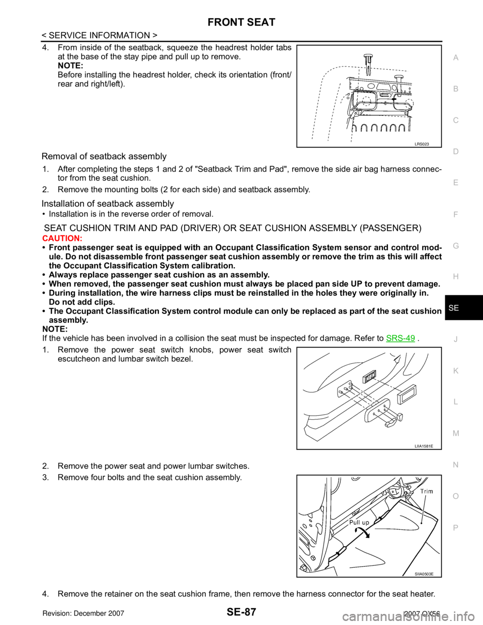
4. From inside of the seatback, squeeze the headrest holder tabs
at the base of the stay pipe and pull up to remove.
NOTE:
Before installing the headrest holder, check its orientation (front/
rear and right/left).
Removal of seatback assembly
1. After completing the steps 1 and 2 of "Seatback Trim and Pad", remove the side air bag harness connec-
tor from the seat cushion.
2. Remove the mounting bolts (2 for each side) and seatback assembly.
Installation of seatback assembly
• Installation is in the reverse order of removal.
SEAT CUSHION TRIM AND PAD (DRIVER) OR SEAT CUSHION ASSEMBLY (PASSENGER)
CAUTION:
• Front passenger seat is equipped with an Occupant Classification System sensor and control mod-
ule. Do not disassemble front passenger seat cushion assembly or remove the trim as this will affect
the Occupant Classification System calibration.
• Always replace passenger seat cushion as an assembly.
• When removed, the passenger seat cushion must always be placed pan side UP to prevent damage.
• During installation, the wire harness clips must be reinstalled in the holes they were originally in.
Do not add clips.
• The Occupant Classification System control module can only be replaced as part of the seat cushion
assembly.
NOTE:
If the vehicle has been involved in a collision the seat must be inspected for damage. Refer to SRS-49
.
1. Remove the power seat switch knobs, power seat switch
escutcheon and lumbar switch bezel.
2. Remove the power seat and power lumbar switches.
3. Remove four bolts and the seat cushion assembly.
4. Remove the retainer on the seat cushion frame, then remove the harness connector for the seat heater.
LRS023
LIIA1581E
SIIA0503E
Page 2760 of 3061
SE-88
< SERVICE INFORMATION >
FRONT SEAT
5. Remove the front seat cushion finisher (inner).
6. On the drivers seat only, after removing the seat cushion trim and pad, remove the hog rings to separate
the trim cover from the pad and seat cushion heater unit.
LIIA0285E