Page 790 of 3061

VEHICLE SECURITY (THEFT WARNING) SYSTEM
BL-79
< SERVICE INFORMATION >
C
D
E
F
G
H
J
K
L
MA
B
BL
N
O
P
Check continuity between main power window and door lock/unlock
switch connector (A) D7 terminals 4, 6 and front door lock assembly
LH (key cylinder switch) connector (B) D14 terminals 1, 6 and body
ground.
OK or NG
OK >> Replace main power window and door lock/unlock switch.
NG >> Repair or replace harness.
Vehicle Security Horn Alarm CheckINFOID:0000000003532953
1.CHECK HORN OPERATION
Check if horn sounds with horn switch.
Does horn operate?
YES >> Check harness for open or short between IPDM E/R and horn relay.
NO >> Check horn circuit. Refer to WW-43
.
Vehicle Security Headlamp Alarm CheckINFOID:0000000003532954
1.CHECK VEHICLE SECURITY HEADLAMP ALARM OPERATION
Check if headlamps operate with lighting switch.
Do headlamps come on when turning switch ON?
YES >> Headlamp alarm is OK.
NO >> Check headlamp system. Refer to LT- 5
or LT- 2 4.
Door Lock/Unlock Switch CheckINFOID:0000000003532955
1.CHECK DOOR LOCK/UNLOCK SWITCH INPUT SIGNAL
Check if power door lock operates with door lock/unlock switch.
Do doors lock/unlock when using each door lock/unlock switch?
YES >> Door lock/unlock switch is OK.
NO >> Refer to "Door Lock/Unlock Switch Check ".
Connector Terminals Connector Terminals Continuity
A: Main
power win-
dow and
door lock/
unlock
switch4 B: Front
door lock
assembly
LH (key
cylinder
switch)1Yes
66Yes
4, 6 Ground No
WIIA0756E
Page 803 of 3061

BL-92
< SERVICE INFORMATION >
AUTOMATIC BACK DOOR SYSTEM
Terminal and Reference Value for BCM
INFOID:0000000003532962
Refer to BCS-11, "Terminal and Reference Value for BCM".
Trouble Diagnosis ProcedureINFOID:0000000003532963
1. Check the trouble symptom and customer's requests.
2. Understand outline of system. Refer to BL-80, "
System Description".
3. Confirm system operation.
4. Perform self-diagnosis procedures. Refer to BL-93, "
Self-Diagnosis Procedure".
5. Refer to diagnosis chart by symptom, repair or replace any malfunctioning parts. Refer to BL-94, "
Diagno-
sis Chart".
6. Inspection End.
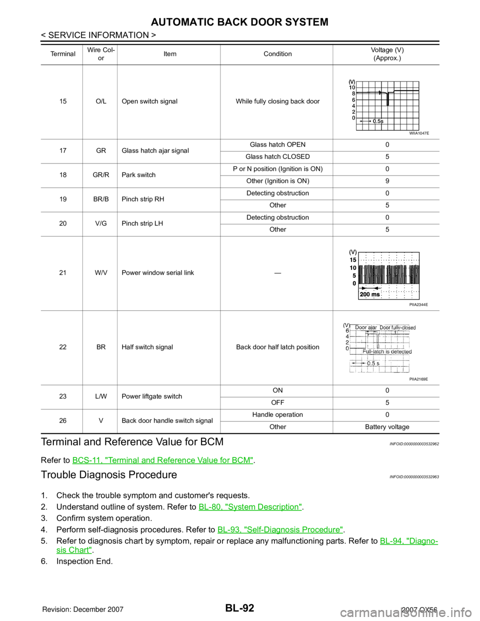
15 O/L Open switch signal While fully closing back door
17 GR Glass hatch ajar signalGlass hatch OPEN 0
Glass hatch CLOSED 5
18 GR/R Park switchP or N position (Ignition is ON) 0
Other (Ignition is ON) 9
19 BR/B Pinch strip RHDetecting obstruction 0
Other 5
20 V/G Pinch strip LHDetecting obstruction 0
Other 5
21 W/V Power window serial link —
22 BR Half switch signal Back door half latch position
23 L/W Power liftgate switchON 0
OFF 5
26 V Back door handle switch signalHandle operation 0
Other Battery voltage Te r m i n a l Wire Col-
orItem ConditionVoltage (V)
(Approx.)
WIIA1047E
PIIA2344E
PIIA2169E
Page 805 of 3061

BL-94
< SERVICE INFORMATION >
AUTOMATIC BACK DOOR SYSTEM
10. After approximately 5 seconds, the back door warning chime will sound for 1 second.
11. Release the power liftgate switch.
12. Immediately close the back door manually.
13. Press and release the power liftgate switch to activate operating check mode.
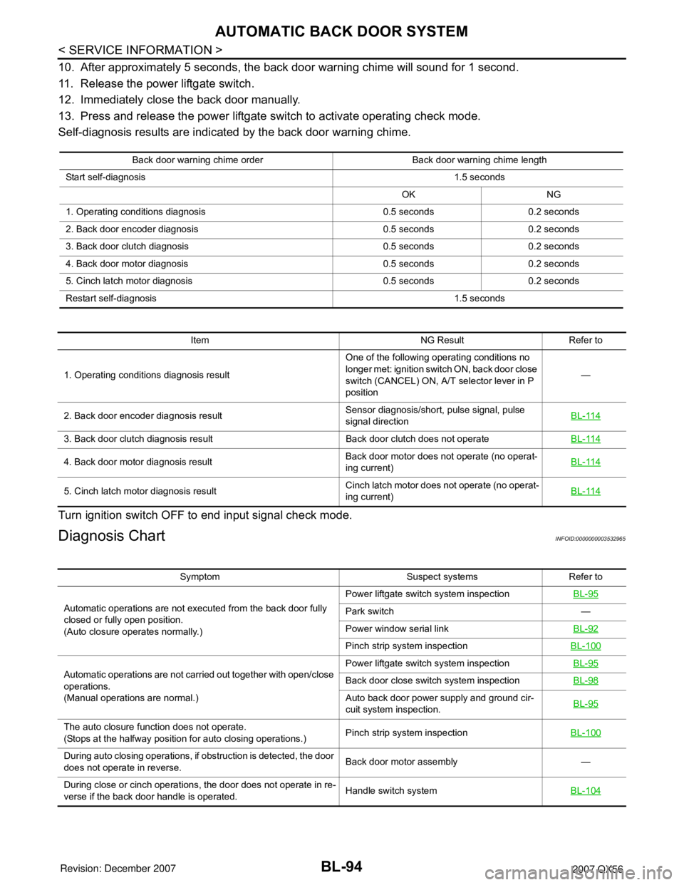
Self-diagnosis results are indicated by the back door warning chime.
Turn ignition switch OFF to end input signal check mode.
Diagnosis ChartINFOID:0000000003532965
Back door warning chime order Back door warning chime length
Start self-diagnosis1.5 seconds
OK NG
1. Operating conditions diagnosis 0.5 seconds 0.2 seconds
2. Back door encoder diagnosis 0.5 seconds 0.2 seconds
3. Back door clutch diagnosis 0.5 seconds 0.2 seconds
4. Back door motor diagnosis 0.5 seconds 0.2 seconds
5. Cinch latch motor diagnosis 0.5 seconds 0.2 seconds
Restart self-diagnosis 1.5 seconds
Item NG Result Refer to
1. Operating conditions diagnosis resultOne of the following operating conditions no
longer met: ignition switch ON, back door close
switch (CANCEL) ON, A/T selector lever in P
position—
2. Back door encoder diagnosis resultSensor diagnosis/short, pulse signal, pulse
signal directionBL-114
3. Back door clutch diagnosis result Back door clutch does not operateBL-114
4. Back door motor diagnosis resultBack door motor does not operate (no operat-
ing current)BL-114
5. Cinch latch motor diagnosis resultCinch latch motor does not operate (no operat-
ing current)BL-114
Symptom Suspect systems Refer to
Automatic operations are not executed from the back door fully
closed or fully open position.
(Auto closure operates normally.)Power liftgate switch system inspectionBL-95
Park switch —
Power window serial linkBL-92
Pinch strip system inspectionBL-100
Automatic operations are not carried out together with open/close
operations.
(Manual operations are normal.)Power liftgate switch system inspectionBL-95Back door close switch system inspectionBL-98
Auto back door power supply and ground cir-
cuit system inspection.BL-95
The auto closure function does not operate.
(Stops at the halfway position for auto closing operations.)Pinch strip system inspectionBL-100
During auto closing operations, if obstruction is detected, the door
does not operate in reverse.Back door motor assembly —
During close or cinch operations, the door does not operate in re-
verse if the back door handle is operated.Handle switch systemBL-104
Page 806 of 3061

AUTOMATIC BACK DOOR SYSTEM
BL-95
< SERVICE INFORMATION >
C
D
E
F
G
H
J
K
L
MA
B
BL
N
O
P
Back Door Power Supply and Ground Circuit InspectionINFOID:0000000003532966
1.BACK DOOR POWER SUPPLY CIRCUIT INSPECTION
1. Turn ignition switch OFF.
2. Disconnect back door control unit.
3. Check voltage between back door control unit connector B55
terminals 3, 10 and ground.
OK or NG
OK >> GO TO 2.
NG >> Repair or replace harness.
2.BACK DOOR GROUND CIRCUIT INSPECTION
Check continuity between back door control unit connector B55 ter-
minal 1, 2 and ground.
OK or NG
OK >> Circuit is OK.
NG >> Repair or replace harness.
Power Liftgate Switch System InspectionINFOID:0000000003532967
1.POWER LIFTGATE SWITCH FUNCTION INSPECTION
Check power liftgate switch using switch operation.
OK or NG
OK >> Power liftgate switch is OK.
NG >> GO TO 2.
When the keyfob is operated, the back door does not operate au-
tomatically.Remote keyless entry system inspectionBL-37Power window serial linkBL-92
Pinch strip system inspectionBL-100
Auto closure does not operate.Half-latch switch systemBL-101Cinch latch motor systemBL-105
Handle switch systemBL-104
The back door does not open.
(Closure motor rotation is not reversed.)Open switch systemBL-102
Handle switch systemBL-104
Warning chime does not sound. Back door warning chime systemBL-101
Auto closure operation works, but the back door is not fully closedClose switch systemBL-103
Handle switch systemBL-104
Cinch latch motor systemBL-105
Back door latch assembly mechanism dam-
aged or worn.— Symptom Suspect systems Refer to
3 - Ground : Approx. battery voltage
10 - Ground : Approx. battery voltage
WIIA0567E
1 - Ground : Continuity should exist.
2 - Ground : Continuity should exist.
LIIA0801E
Page 818 of 3061

DOOR
BL-107
< SERVICE INFORMATION >
C
D
E
F
G
H
J
K
L
MA
B
BL
N
O
P
1. Adjust the striker so that it becomes parallel with the lock inser-
tion direction.
Removal and InstallationINFOID:0000000003532978
FRONT DOOR
Removal
CAUTION:
• When removing and installing the door assembly, support the door with a jack and shop cloth to pro-
tect the door and body.
• When removing and installing door assembly, be sure to carry out the fitting adjustment.
• Check the hinge rotating part for poor lubrication. If necessary, apply "body grease".
1. Remove the door window and module assembly. Refer to GW-59
.
2. Remove the door harness.
3. Remove the check link cover.
4. Remove the check link bolt from the hinge pillar.
5. Remove the door-side hinge nuts and bolts, and remove the
door assembly.
Installation
Installation is in the reverse order of removal.
REAR DOOR
Removal
CAUTION:
• When removing and installing the door assembly, support the door with a jack and shop cloth to pro-
tect the door and body.
• When removing and installing door assembly, be sure to carry out the fitting adjustment.
• Check the hinge rotating part for poor lubrication. If necessary, apply "body grease".
LIIA1502E
LIIA1503E
LIIA1504E
Page 819 of 3061

BL-108
< SERVICE INFORMATION >
DOOR
1. Remove the door window and module assembly. Refer to GW-62.
2. Remove the door harness.
3. Remove the check link cover.
4. Remove the check link bolt from the hinge pillar.
5. Remove the door-side hinge nuts and bolts, and remove the
door assembly.
Installation
Installation is in the reverse order of removal.
BACK DOOR
Removal
WARNING:
Always support back door when removing or replacing back door stays. Power back door opener will
not support back door with back door stays removed.
1. Remove the back door glass. Refer to GW-13
.
2. Remove the back door lock assembly. Refer to BL-114
.
3. Remove the rear wiper motor. Refer to WW-37, "
Rear Wiper Motor".
4. Remove the back door wire harness.
5. Remove the rear washer nozzle and hose from the back door. Refer to WW-39, "
Rear Washer Nozzle".
CAUTION:
Two technicians should be used to avoid damaging the back door during removal.
6. Support the back door.
7. Disconnect the power back door lift arm from the door.
8. Remove the back door stays.
LIIA1503E
LIIA1504E
Page 821 of 3061
BL-110
< SERVICE INFORMATION >
FRONT DOOR LOCK
FRONT DOOR LOCK
Component StructureINFOID:0000000003532979
Removal and InstallationINFOID:0000000003532980
REMOVAL
1. Remove the front door window regulator. Refer to GW-59, "Removal and Installation".
2. Remove the front door window rear glass run.
3. Remove the door side grommet, and the bolt (TORX T30) from
the grommet hole.
1. Grommet 2. Front door striker 3. Door lock assembly
4. Outside handle cable 5. Inside handle assembly 6. Inside handle cable
7. Door lock cable 8. Key cylinder rod (Driver side only) 9. Key cylinder
10. Outside handle bracket 11. Front gasket 12. Outside handle
13. Door key cylinder assembly (Driver
side) Outside handle escutcheon
(Passenger side)14. Rear gasket
WIIA0891E
PIIA3553E
Page 824 of 3061
REAR DOOR LOCK
BL-113
< SERVICE INFORMATION >
C
D
E
F
G
H
J
K
L
MA
B
BL
N
O
P
REAR DOOR LOCK
Component StructureINFOID:0000000003532982
Removal and InstallationINFOID:0000000003532983
REMOVAL
1. Remove the rear door window and rear door module assembly. Refer to GW-62.
2. Remove door grommets, and remove outside handle nuts from grommet hole.
3. Remove outside handle.
4. Disconnect the door lock actuator connector.
5. Separate outside handle rod connection.
INSTALLATION
Installation is in the reverse order of removal.
WIIA0892E