2007 INFINITI QX56 window
[x] Cancel search: windowPage 2030 of 3061
WINDSHIELD GLASS
GW-11
< SERVICE INFORMATION >
C
D
E
F
G
H
J
K
L
MA
B
GW
N
O
P
WINDSHIELD GLASS
Removal and InstallationINFOID:0000000003533022
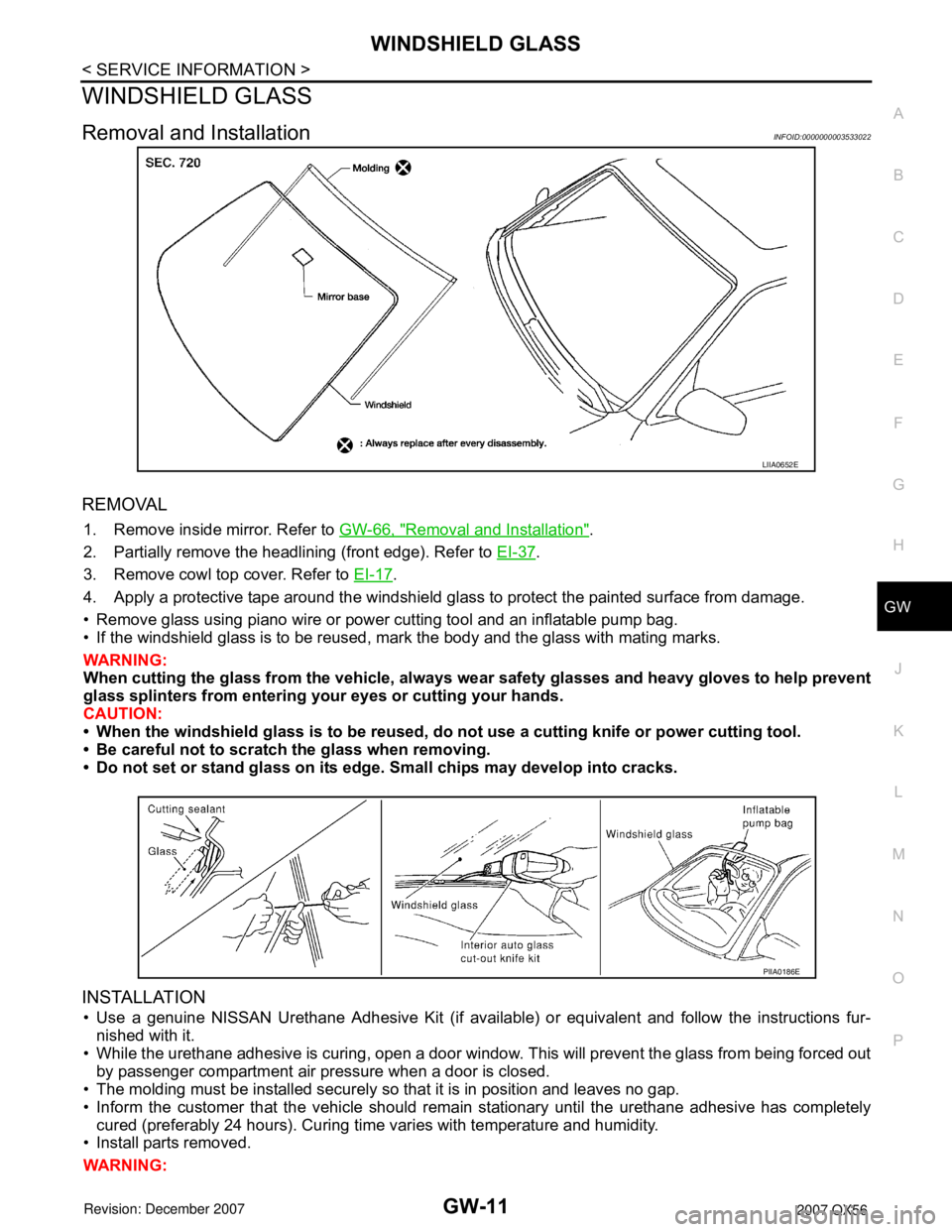
REMOVAL
1. Remove inside mirror. Refer to GW-66, "Removal and Installation".
2. Partially remove the headlining (front edge). Refer to EI-37
.
3. Remove cowl top cover. Refer to EI-17
.
4. Apply a protective tape around the windshield glass to protect the painted surface from damage.
• Remove glass using piano wire or power cutting tool and an inflatable pump bag.
• If the windshield glass is to be reused, mark the body and the glass with mating marks.
WARNING:
When cutting the glass from the vehicle, always wear safety glasses and heavy gloves to help prevent
glass splinters from entering your eyes or cutting your hands.
CAUTION:
• When the windshield glass is to be reused, do not use a cutting knife or power cutting tool.
• Be careful not to scratch the glass when removing.
• Do not set or stand glass on its edge. Small chips may develop into cracks.
INSTALLATION
• Use a genuine NISSAN Urethane Adhesive Kit (if available) or equivalent and follow the instructions fur-
nished with it.
• While the urethane adhesive is curing, open a door window. This will prevent the glass from being forced out
by passenger compartment air pressure when a door is closed.
• The molding must be installed securely so that it is in position and leaves no gap.
• Inform the customer that the vehicle should remain stationary until the urethane adhesive has completely
cured (preferably 24 hours). Curing time varies with temperature and humidity.
• Install parts removed.
WARNING:
LIIA0652E
PIIA0186E
Page 2032 of 3061
REAR WINDOW GLASS AND MOLDING
GW-13
< SERVICE INFORMATION >
C
D
E
F
G
H
J
K
L
MA
B
GW
N
O
P
REAR WINDOW GLASS AND MOLDING
Removal and InstallationINFOID:0000000003533023
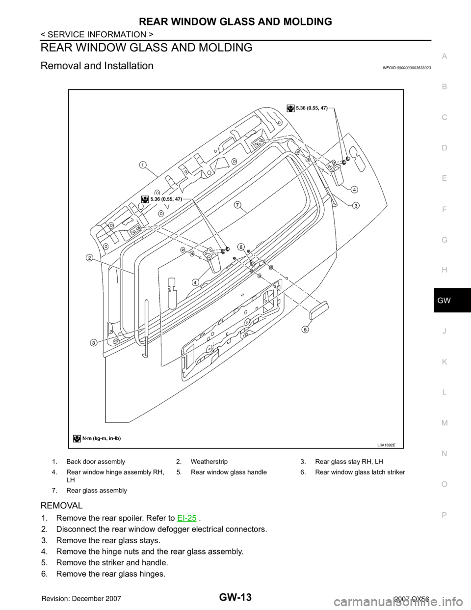
REMOVAL
1. Remove the rear spoiler. Refer to EI-25 .
2. Disconnect the rear window defogger electrical connectors.
3. Remove the rear glass stays.
4. Remove the hinge nuts and the rear glass assembly.
5. Remove the striker and handle.
6. Remove the rear glass hinges.
1. Back door assembly 2. Weatherstrip 3. Rear glass stay RH, LH
4. Rear window hinge assembly RH,
LH5. Rear window glass handle 6. Rear window glass latch striker
7. Rear glass assembly
LIIA1892E
Page 2033 of 3061

GW-14
< SERVICE INFORMATION >
REAR WINDOW GLASS AND MOLDING
INSTALLATION
Installation is in the reverse order of removal.
Page 2034 of 3061
POWER WINDOW SYSTEM
GW-15
< SERVICE INFORMATION >
C
D
E
F
G
H
J
K
L
MA
B
GW
N
O
P
POWER WINDOW SYSTEM
Component Parts and Harness Connector LocationINFOID:0000000003533024
System DescriptionINFOID:0000000003533025
Power is supplied at all time
• from 50A fusible link (letter f, located in the fuse and fusible link box)
• to BCM terminal 70
• through BCM terminal 69
• to main power window and door lock/unlock switch terminal 19
• to power window and door lock/unlock switch RH terminal 10.
With ignition switch in ON or START position, power is supplied
• through 10A fuse (No. 59, located in the fuse and relay box)
• to BCM terminal 38
• through BCM terminal 68
• to main power window and door lock/unlock switch terminal 10.
• to rear power vent window relays (OPEN and CLOSE) terminal 1.
With ignition switch in ON or START position, ground is supplied
• to BCM terminal 67
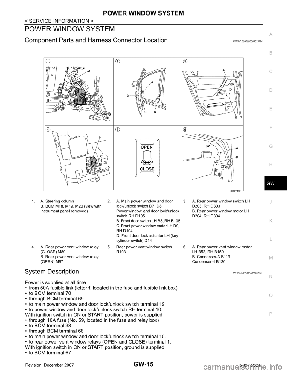
1. A. Steering column
B. BCM M18, M19, M20 (view with
instrument panel removed)2. A. Main power window and door
lock/unlock switch D7, D8
Power window and door lock/unlock
switch RH D105
B. Front door switch LH B8, RH B108
C. Front power window motor LH D9,
RH D104
D. Front door lock actuator LH (key
cylinder switch) D143. A. Rear power window switch LH
D203, RH D303
B. Rear power window motor LH
D204, RH D304
4. A. Rear power vent window relay
(CLOSE) M89
B. Rear power vent window relay
(OPEN) M875. Rear power vent window switch
R1036. A. Rear power vent window motor
LH B52, RH B150
B. Condenser-3 B119
Condenser-4 B120
LIIA2715E
Page 2035 of 3061

GW-16
< SERVICE INFORMATION >
POWER WINDOW SYSTEM
• to main power window and door lock/unlock switch terminal 17
• to power window and door lock/unlock switch RH terminal 11
• through body grounds M57, M61 and M79.
MANUAL OPERATION
Front Door LH
WINDOW UP
When the front LH switch in the main power window and door lock/unlock switch is pressed in the up position,
power is supplied
• through main power window and door lock/unlock switch terminal 8
• to front power window motor LH terminal 2.
Ground is supplied
• through main power window and door lock/unlock switch terminal 11
• to front power window motor LH terminal 1.
Then, the motor raises the window until the switch is released.
WINDOW DOWN
When the front LH switch in the main power window and door lock/unlock switch is pressed in the down posi-
tion, power is supplied
• through main power window and door lock/unlock switch terminal 11
• to front power window motor LH terminal 1.
Ground is supplied
• through main power window and door lock/unlock switch terminal 8
• to front power window motor LH terminal 2.
Then, the motor lowers the window until the switch is released.
Front Door RH
POWER WINDOW AND DOOR LOCK/UNLOCK SWITCH RH OPERATION
WINDOW UP
When the power window and door lock/unlock switch RH is pressed in the up position, power is supplied
• through power window and door lock/unlock switch RH terminal 8
• to front power window motor RH terminal 2.
Ground is supplied
• through power window and door lock/unlock switch RH terminal 9
• to front power window motor RH terminal 1.
Then, the motor raises the window until the switch is released.
WINDOW DOWN
When the power window and door lock/unlock switch RH is pressed in the down position, power is supplied
• through power window and door lock/unlock switch RH terminal 9
• to front power window motor RH terminal 1.
Ground is supplied
• through power window and door lock/unlock switch RH terminal 8
• to front power window motor RH terminal 2.
Then, the motor lowers the window until the switch is released.
MAIN POWER WINDOW AND DOOR LOCK/UNLOCK SWITCH OPERATION
Signal is sent
• through main power window and door lock/unlock switch terminal 14
• to power window and door lock/unlock switch RH terminal 16.
The operation of power window after receiving the signal is the same as operating the power window with
power window and door lock/unlock switch RH.
Rear Door (LH or RH)
REAR POWER WINDOW SWITCH LH OR RH OPERATION
WINDOW UP
When the rear power window switch LH or RH is pressed in the up position, power is supplied
• to rear power window control unit LH or RH terminal 13
• through rear power window control unit LH or RH terminal 7
• through rear power window switch LH or RH terminal 2 and 3
• through rear power window switch LH or RH terminal 5
• through rear power window control unit LH or RH terminal 11
• to rear power window motor LH or RH terminal 2.
Ground is supplied
• to rear power window control unit LH or RH terminal 15
Page 2036 of 3061

POWER WINDOW SYSTEM
GW-17
< SERVICE INFORMATION >
C
D
E
F
G
H
J
K
L
MA
B
GW
N
O
P
• through rear power window control unit LH or RH terminal 16
• through rear power window switch LH or RH terminal 1 and 7
• through rear power window switch LH or RH terminal 4
• through rear power window control unit LH or RH terminal 12
• to rear power window motor LH or RH terminal 1.
Then, the motor raises the window until the switch is released.
WINDOW DOWN
When the rear power window switch LH or RH is pressed in the down position, power is supplied
• to rear power window control unit LH or RH terminal 1
• through rear power window control unit LH or RH terminal 7
• through rear power window switch LH or RH terminal 2 and 3
• through rear power window switch LH or RH terminal 4
• through rear power window control unit LH or RH terminal 12
• to rear power window motor LH or RH terminal 1.
Ground is supplied
• to rear power window control unit LH or RH terminal 15
• through rear power window control unit LH or RH terminal 16
• through rear power window switch LH or RH terminal 1 and 7
• through rear power window switch LH or RH terminal 5
• through rear power window control unit LH or RH terminal 11
• to rear power window motor LH or RH terminal 2.
Then, the motor lowers the window until the switch is released.
MAIN POWER WINDOW AND DOOR LOCK/UNLOCK SWITCH OPERATION
Signal is sent
• through main power window and door lock/unlock switch terminal 14
• to rear power window control unit LH or RH terminal 1.
The operation of power window after receiving the signal is the same as operating the power window with rear
power window switch LH or RH.
VENT WINDOW CLOSE
When the rear power vent window switch is pressed in the close position, power is supplied
• to rear power vent window relay (CLOSE) terminal 5
• through rear power vent window relay (CLOSE) terminal 3
• to rear power vent window motors terminal 2.
Ground is supplied
• to rear power vent window relay (OPEN) terminal 4
• through rear power vent window relay (OPEN) terminal 3
• to rear power vent window motors terminal 1.
Then, the motors close the windows until the switch is released.
VENT WINDOW OPEN
When the main power window and door lock/unlock switch (rear LH) is pressed in the open position, power is
supplied
• to rear power vent window relay (OPEN) terminal 5
• through rear power vent window relay (OPEN) terminal 3
• to rear power vent window motors terminal 1.
Ground is supplied
• to rear power vent window relay (CLOSE) terminal 4
• through rear power vent window relay (CLOSE) terminal 3
• to rear power vent window motors terminal 2.
Then, the motors open the windows until the switch is released.
AUTO OPERATION
The power window AUTO feature enables the driver to open or close the window without holding the window
switch in the down or up position.
POWER WINDOW SERIAL LINK
Main power window and door lock/unlock switch, power window and door lock/unlock switch RH, rear power
window control units and BCM transmit and receive the signal by power window serial link.
The signal is transmitted from BCM to main power window and door lock/unlock switch and power window and
door lock/unlock switch RH
• Keyless power window down signal.
• Rear power window switch illumination.
Page 2037 of 3061
GW-18
< SERVICE INFORMATION >
POWER WINDOW SYSTEM
The signal is transmitted from main power window and door lock/unlock switch to power window and door
lock/unlock switch RH
• Front door window RH operation signal.
• Power window control by front door lock assembly LH (key cylinder switch) signal.
• Power window lock signal.
• Retained power operation signal.
• Rear power window operation.
POWER WINDOW LOCK
The power window lock is designed to lock operation of all windows except for front door window LH.
When in the lock position, the power window lock signal is transmitted to power window and door lock/unlock
switch RH by power window serial link. This prevents the power window motor from operating.
RETAINED POWER OPERATION
When the ignition switch is turned to the OFF position from ON or START position, power is supplied for 45
seconds
• to main power window and door lock/unlock switch terminal 10
• from BCM terminal 68.
When power and ground are supplied, the BCM continues to be energized, and the power window can be
operated.
The retained power operation is canceled when the front LH or front RH door is opened.
Retained power operation period can be changed by CONSULT-II. Refer to GW-31, "
CONSULT-II Function
(BCM)" .
ANTI-PINCH SYSTEM
Main power window and door lock/unlock switch, power window and door lock/unlock switch RH and rear
power window control unit LH and RH monitors the power window motor operation and the power window
position (full closed or other) for each power window by the signals from encoder and limit switch in power win-
dow motor.
When a window switch detects interruption during the following close operation,
• automatic close operation when ignition switch is in the ON position
• automatic close operation during retained power operation
Main power window and door lock/unlock switch, power window and door lock/unlock switch RH and rear
power window control unit LH and RH controls each power window motor for open and the power window will
be lowered about 150 mm (5.91 in).
POWER WINDOW CONTROL BY THE FRONT DOOR LOCK ASSEMBLY LH (KEY CYLINDER
SWITCH)
When ignition key switch is OFF, front power window LH and RH can be opened or closed by turning the front
door lock assembly LH (key cylinder switch) to the UNLOCK/LOCK position for more than 1 second.
• Front power windows can be opened as the front door lock assembly LH (key cylinder switch) is kept fully
turned to the UNLOCK position.
• Front power windows can be closed as the front door lock assembly LH (key cylinder switch) is kept fully
turned to the LOCK position.
• While performing open/close operation for the windows, power window is stopped when the front door lock
assembly LH (key cylinder switch) is placed in the NEUTRAL position.
• When the ignition switch is turned ON while the power window opening operation is performed, the power
window opening stops.
CAN Communication System DescriptionINFOID:0000000003533026
Refer to LAN-4.
Page 2038 of 3061
POWER WINDOW SYSTEM
GW-19
< SERVICE INFORMATION >
C
D
E
F
G
H
J
K
L
MA
B
GW
N
O
P
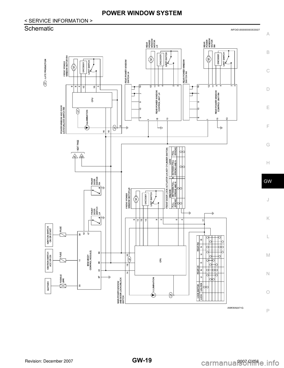
SchematicINFOID:0000000003533027
AWKWA0471G