2007 INFINITI QX56 window
[x] Cancel search: windowPage 2422 of 3061

PG-20
< SERVICE INFORMATION >
IPDM E/R (INTELLIGENT POWER DISTRIBUTION MODULE ENGINE ROOM)
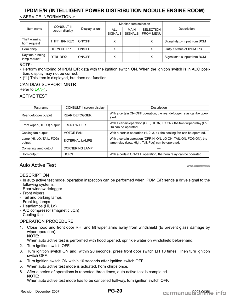
NOTE:
• Perform monitoring of IPDM E/R data with the ignition switch ON. When the ignition switch is in ACC posi-
tion, display may not be correct.
• (*1) This item is displayed, but does not function.
CAN DIAG SUPPORT MNTR
Refer to LAN-4.
ACTIVE TEST
Auto Active TestINFOID:0000000003533839
DESCRIPTION
• In auto active test mode, operation inspection can be performed when IPDM E/R sends a drive signal to the
following systems:
- Rear window defogger
- Front wipers
- Tail and parking lamps
- Front fog lamps
- Headlamps (Hi, Lo)
- A/C compressor (magnet clutch)
- Cooling fan
OPERATION PROCEDURE
1. Close hood and front door RH, and lift wiper arms away from windshield (to prevent glass damage by
wiper operation).
NOTE:
When auto active test is performed with hood opened, sprinkle water on windshield beforehand.
2. Turn ignition switch OFF.
3. Turn ignition switch ON and, within 20 seconds, press front door switch LH 10 times. Then turn ignition
switch OFF.
4. Turn ignition switch ON within 10 seconds after ignition switch OFF.
5. When auto active test mode is actuated, horn chirps once.
6. After a series of operations is repeated three times, auto active test is completed.
NOTE:
When auto active test mode has to be cancelled halfway, turn ignition switch OFF.
Theft warning
horn requestTHFT HRN REQ ON/OFF X X Signal status input from BCM
Horn chirp HORN CHIRP ON/OFF X X Output status of IPDM E/R
Daytime running
lamp requestDTRL REQ ON/OFF X X Signal status input from BCM Item nameCONSULT-II
screen displayDisplay or unitMonitor item selection
Description
ALL
SIGNALSMAIN
SIGNALSSELECTION
FROM MENU
Test name CONSULT-II screen display Description
Rear defogger output REAR DEFOGGERWith a certain ON-OFF operation, the rear defogger relay can be oper-
ated.
Front wiper (HI, LO) output FRONT WIPERWith a certain operation (OFF, HI ON, LO ON), the front wiper relay (Lo,
Hi) can be operated.
Cooling fan output MOTOR FAN With a certain operation (1, 2, 3, 4), the cooling fan can be operated.
Lamp (HI, LO, TAIL, FOG)
outputEXTERNAL LAMPSWith a certain operation (OFF, HI ON, LO ON, TAIL ON, FOG ON), the
lamp relay (Low, High, Tail, Fog) can be operated.
Cornering lamp output CORNERING LAMP —
Horn output HORN With a certain ON-OFF operation, the horn relay can be operated.
Page 2423 of 3061

IPDM E/R (INTELLIGENT POWER DISTRIBUTION MODULE ENGINE ROOM)
PG-21
< SERVICE INFORMATION >
C
D
E
F
G
H
I
J
L
MA
B
PG
N
O
P
CAUTION:
Be sure to perform BL-25, "
Door Switch Check" when the auto active test cannot be performed.
INSPECTION IN AUTO ACTIVE TEST MODE
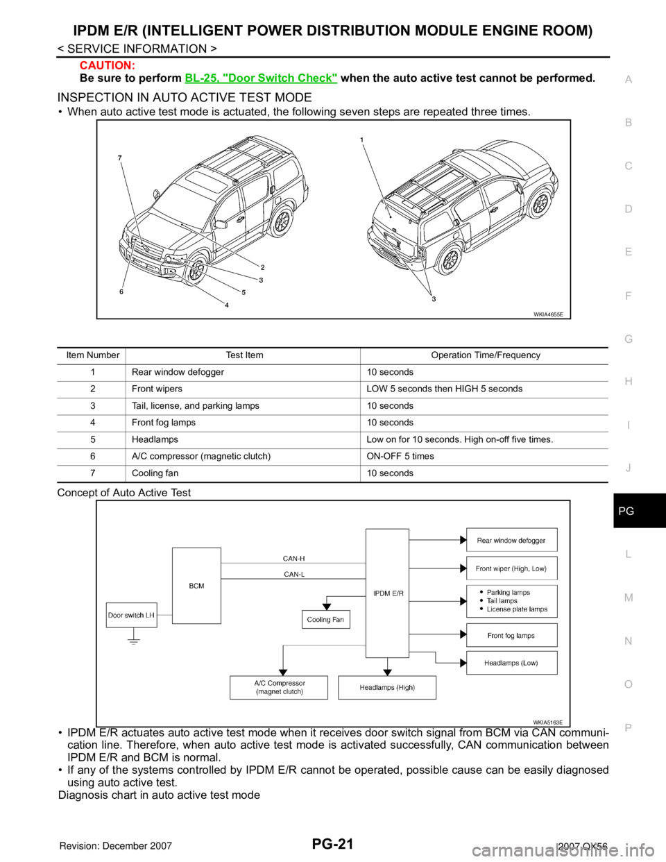
• When auto active test mode is actuated, the following seven steps are repeated three times.
Concept of Auto Active Test
• IPDM E/R actuates auto active test mode when it receives door switch signal from BCM via CAN communi-
cation line. Therefore, when auto active test mode is activated successfully, CAN communication between
IPDM E/R and BCM is normal.
• If any of the systems controlled by IPDM E/R cannot be operated, possible cause can be easily diagnosed
using auto active test.
Diagnosis chart in auto active test mode
WKIA4655E
Item Number Test Item Operation Time/Frequency
1 Rear window defogger 10 seconds
2 Front wipers LOW 5 seconds then HIGH 5 seconds
3 Tail, license, and parking lamps 10 seconds
4 Front fog lamps 10 seconds
5 Headlamps Low on for 10 seconds. High on-off five times.
6 A/C compressor (magnetic clutch) ON-OFF 5 times
7 Cooling fan 10 seconds
WKIA5163E
Page 2424 of 3061

PG-22
< SERVICE INFORMATION >
IPDM E/R (INTELLIGENT POWER DISTRIBUTION MODULE ENGINE ROOM)
Terminal and Reference Value for IPDM E/R
INFOID:0000000003533840
Symptom Inspection contents Possible cause
Rear window defogger
does not operate.Perform auto active
test. Does rear win-
dow defogger oper-
ate?YES • BCM signal input circuit
NO• Rear window defogger relay
• Open circuit of rear window defogger
•IPDM E/R malfunction
• Harness or connector malfunction between IPDM E/R and rear window
defogger
Any of front wipers, tail
and parking lamps, front
fog lamps, and head-
lamps (Hi, Lo) do not op-
erate.Perform auto active
test. Does system in
question operate?YES • BCM signal input system
NO• Lamp/wiper motor malfunction
• Lamp/wiper motor ground circuit malfunction
• Harness/connector malfunction between IPDM E/R and system in ques-
tion
• IPDM E/R (integrated relay) malfunction
A/C compressor does
not operate.Perform auto active
test. Does magnet
clutch operate?YES• BCM signal input circuit
• CAN communication signal between BCM and ECM
• CAN communication signal between ECM and IPDM E/R
NO• Magnet clutch malfunction
• Harness/connector malfunction between IPDM E/R and magnet clutch
• IPDM E/R (integrated relay) malfunction
Cooling fan does not op-
erate.Perform auto active
test. Does cooling fan
operate?YES• ECM signal input circuit
• CAN communication signal between ECM and IPDM E/R
NO• Cooling fan motor malfunction
• Harness/connector malfunction between IPDM E/R and cooling fan mo-
tor
• IPDM E/R (integrated relay) malfunction
Te r m i n a lWire
colorSignal nameSignal
input/
outputMeasuring condition
Reference value
(Approx.) Igni-
tion
switchOperation or condition
1 B/Y Battery power supply Input OFF — Battery voltage
2 R Battery power supply Input OFF — Battery voltage
3 BR ECM relay Output —Ignition switch ON or START Battery voltage
Ignition switch OFF or ACC 0V
4 W/L ECM relay Output —Ignition switch ON or START Battery voltage
Ignition switch OFF or ACC 0V
6LThrottle control motor
relayOutput —Ignition switch ON or START Battery voltage
Ignition switch OFF or ACC 0V
7 W/B ECM relay control Input —Ignition switch ON or START 0V
Ignition switch OFF or ACC Battery voltage
8 R/B Fuse 54 Output —Ignition switch ON or START Battery voltage
Ignition switch OFF or ACC 0V
10 GDaytime light relay
controlOutput ONDaytime light system active 0V
Daytime light system inactive Battery voltage
11 Y/B A/C compressor OutputON or
STARTA/C switch ON or defrost A/C
switchBattery voltage
A/C switch OFF or defrost A/C
switch0V
Page 2426 of 3061

PG-24
< SERVICE INFORMATION >
IPDM E/R (INTELLIGENT POWER DISTRIBUTION MODULE ENGINE ROOM)
43 L/Y Wiper auto stop signal InputON or
STARTWiper switch OFF, LO, INT Battery voltage
44 BRDaytime light relay
controlInput ONDaytime light system active 0V
Daytime light system inactive Battery voltage
45 G/W Horn relay control Input ONWhen door locks are operated
using key fob (OFF → ON)*1Battery voltage → 0V
46 GRFuel pump relay con-
trolInput —Ignition switch ON or START 0V
Ignition switch OFF or ACC Battery voltage
47 OThrottle control motor
relay controlInput —Ignition switch ON or START 0V
Ignition switch OFF or ACC Battery voltage
48 B/RStarter relay (inhibit
switch)InputON or
STARTSelector lever in "P" or "N" 0V
Selector lever any other posi-
tionBattery voltage
49 R/L Trailer tow relay Output ONLighting
switch must
be in the 1st
positionOFF 0V
ON Battery voltage
50 W/R Front fog lamp (LH) OutputON or
STARTLighting
switch must
be in the 2nd
position
(LOW beam
is ON) and
the front fog
lamp switchOFF 0V
ON Battery voltage
51 W/R Front fog lamp (RH) OutputON or
STARTLighting
switch must
be in the 2nd
position
(LOW beam
is ON) and
the front fog
lamp switchOFF 0V
ON Battery voltage
52 LLH low beam head-
lampOutput — Lighting switch in 2nd position Battery voltage
54 R/YRH low beam head-
lampOutput — Lighting switch in 2nd position Battery voltage
55 GLH high beam head-
lampOutput —Lighting switch in 2nd position
and placed in HIGH or PASS
positionBattery voltage
56L/W*2
Y*3LH high beam head-
lampOutput —Lighting switch in 2nd position
and placed in HIGH or PASS
positionBattery voltage
57 R/LParking, license, and
tail lampOutput ONLighting
switch 1st po-
sitionOFF 0V
ON Battery voltage
59 B Ground Input — — 0V
60 B/WRear window defog-
ger relayOutputON or
STARTRear defogger switch ON Battery voltage
Rear defogger switch OFF 0V Te r m i n a lWire
colorSignal nameSignal
input/
outputMeasuring condition
Reference value
(Approx.) Igni-
tion
switchOperation or condition
Page 2462 of 3061

PG-60
< SERVICE INFORMATION >
HARNESS
Code Section Wiring Diagram Name
A/C,A ATC Auto Air Conditioner
A/SUSP RSU Rear Air Suspension
AF1B1 EC Air Fuel Ratio (A/F) Sensor 1 (Bank 1)
AF1B2 EC Air Fuel Ratio (A/F) Sensor 1 (Bank 2)
AF1HB1 EC Air Fuel Ratio (A/F) Sensor 1 (Bank 1)
AF1HB2 EC Air Fuel Ratio (A/F) Sensor 1 (Bank 2)
APPS1 EC Accelerator Pedal Position Sensor
APPS2 EC Accelerator Pedal Position Sensor
APPS3 EC Accelerator Pedal Position Sensor
ASC/BS EC ASCD Brake Switch
ASC/SW EC ASCD Steering Switch
ASCBOF EC ASCD Brake Switch
ASCIND EC ASCD Indicator
A/T AT A/T Assembly
AT/IND DI A/T Indicator Lamp
AUDIO AV Audio
AUT/DP SE Automatic Drive Positioner
AUTO/L LT Auto Light Control
B/CLOS BL Back Door Auto Closure System
BACK/L LT Back-up Lamp
BRK/SW EC Brake Switch
CAN EC CAN Communication Line
CAN LAN CAN System
CHARGE SC Charging System
CHIME DI Warning Chime
CLOCK DI Clock
COOL/F EC Cooling Fan Control
COMBSW LT Combination Switch
COMM AV Audio Visual Communication System
COMPAS DI Compass and Thermometer
D/LOCK BL Power Door Lock
DEF GW Rear Window Defogger
DTRL LT Headlamp - With Daytime Light System
DVD AV DVD Entertainment System
ECM/PW EC ECM Power Supply for Back-Up
ECTS EC Engine Coolant Temperature Sensor
ETC1 EC Electric Throttle Control Function
ETC2 EC Throttle Control Motor Relay
ETC3 EC Throttle Control Motor
F/FOG LT Front Fog Lamp
F/PUMP EC Fuel Pump
FTTS EC Fuel Tank Temperature Sensor
FUELB1 EC Fuel Injection System Bank 1
FUELB2 EC Fuel Injection System Bank 2
H/AIM LT Headlamp Aiming Control
H/PHON AV Hands Free Telephone
H/LAMP LT Headlamp
HORN WW Horn
HSEAT SE Heated Seat
ICC ACS Intelligent Cruise Control
ICCBOF EC ICC Brake Switch
Page 2464 of 3061

PG-62
< SERVICE INFORMATION >
HARNESS
WINDOW GW Power Window
WIP/R WW Rear Wiper and Washer
WIPER WW Front Wiper and Washer
Page 2547 of 3061

SUNROOF
RF-15
< SERVICE INFORMATION >
C
D
E
F
G
H
J
K
L
MA
B
RF
N
O
P
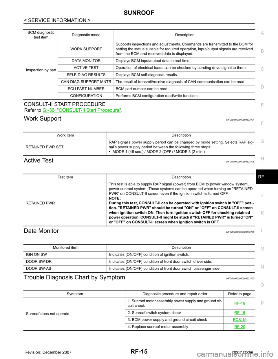
CONSULT-II START PROCEDURE
Refer to GI-36, "CONSULT-II Start Procedure".
Work SupportINFOID:0000000003533104
Active TestINFOID:0000000003533105
Data MonitorINFOID:0000000003533106
Trouble Diagnosis Chart by SymptomINFOID:0000000003533107
BCM diagnostic
test itemDiagnostic mode Description
Inspection by partWORK SUPPORTSupports inspections and adjustments. Commands are transmitted to the BCM for
setting the status suitable for required operation, input/output signals are received
from the BCM and received data is displayed.
DATA MONITOR Displays BCM input/output data in real time.
ACTIVE TEST Operation of electrical loads can be checked by sending drive signal to them.
SELF-DIAG RESULTS Displays BCM self-diagnosis results.
CAN DIAG SUPPORT MNTR The result of transmit/receive diagnosis of CAN communication can be read.
ECU PART NUMBER BCM part number can be read.
CONFIGURATION Performs BCM configuration read/write functions.
Work item Description
RETAINED PWR SETRAP signal’s power supply period can be changed by mode setting. Selects RAP sig-
nal’s power supply period between the following three steps:
• MODE 1 (45 sec.) / MODE 2 (OFF) / MODE 3 (2 min.)
Test item Description
RETAINED PWRThis test is able to supply RAP signal (power) from BCM to power window system,
power sunroof system. Those systems can be operated when turning on "RETAINED
PWR" on CONSULT-II screen even if the ignition switch is turned OFF.
NOTE:
During this test, CONSULT-II can be operated with ignition switch in "OFF" posi-
tion. "RETAINED PWR" should be turned "ON" or "OFF" on CONSULT-II screen
when ignition switch ON. Then turn ignition switch OFF for checking retained
power operation. CONSULT-II might be stuck if "RETAINED PWR" is turned "ON"
or "OFF" on CONSULT-II screen when ignition switch is OFF.
Monitored item Description
IGN ON SW Indicates [ON/OFF] condition of ignition switch.
DOOR SW-DR Indicates [ON/OFF] condition of front door switch driver side.
DOOR SW-AS Indicates [ON/OFF] condition of front door switch passenger side.
Symptom Diagnostic procedure and repair order Refer to page
Sunroof does not operate.1. Sunroof motor assembly power supply and ground cir-
cuit checkRF-16
2. Sunroof switch system checkRF-16
3. BCM power supply and ground circuit checkBCS-15
4. Replace sunroof motor assemblyRF-20
Page 2666 of 3061

SC-18
< SERVICE INFORMATION >
CHARGING SYSTEM
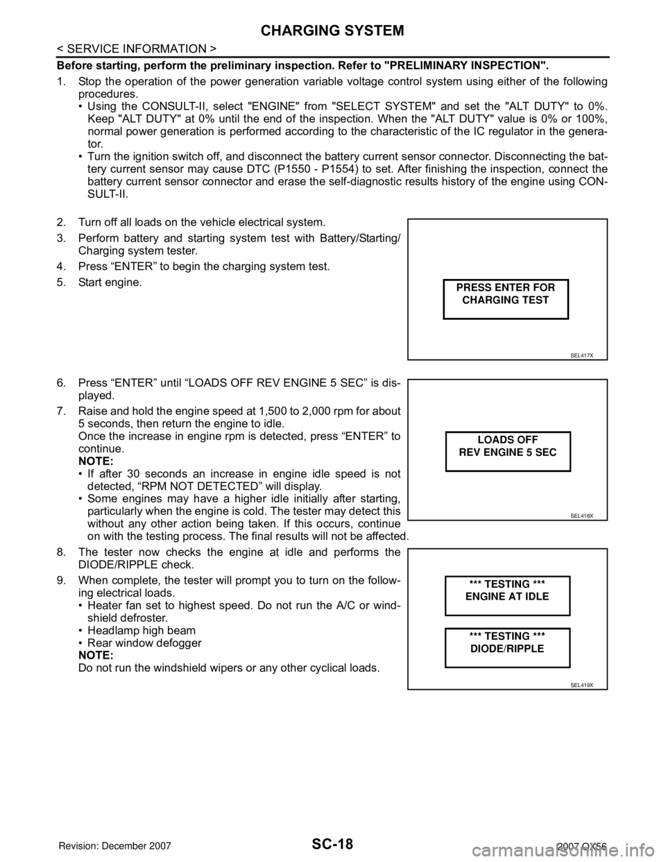
Before starting, perform the preliminary inspection. Refer to "PRELIMINARY INSPECTION".
1. Stop the operation of the power generation variable voltage control system using either of the following
procedures.
• Using the CONSULT-II, select "ENGINE" from "SELECT SYSTEM" and set the "ALT DUTY" to 0%.
Keep "ALT DUTY" at 0% until the end of the inspection. When the "ALT DUTY" value is 0% or 100%,
normal power generation is performed according to the characteristic of the IC regulator in the genera-
tor.
• Turn the ignition switch off, and disconnect the battery current sensor connector. Disconnecting the bat-
tery current sensor may cause DTC (P1550 - P1554) to set. After finishing the inspection, connect the
battery current sensor connector and erase the self-diagnostic results history of the engine using CON-
SULT-II.
2. Turn off all loads on the vehicle electrical system.
3. Perform battery and starting system test with Battery/Starting/
Charging system tester.
4. Press “ENTER” to begin the charging system test.
5. Start engine.
6. Press “ENTER” until “LOADS OFF REV ENGINE 5 SEC” is dis-
played.
7. Raise and hold the engine speed at 1,500 to 2,000 rpm for about
5 seconds, then return the engine to idle.
Once the increase in engine rpm is detected, press “ENTER” to
continue.
NOTE:
• If after 30 seconds an increase in engine idle speed is not
detected, “RPM NOT DETECTED” will display.
• Some engines may have a higher idle initially after starting,
particularly when the engine is cold. The tester may detect this
without any other action being taken. If this occurs, continue
on with the testing process. The final results will not be affected.
8. The tester now checks the engine at idle and performs the
DIODE/RIPPLE check.
9. When complete, the tester will prompt you to turn on the follow-
ing electrical loads.
• Heater fan set to highest speed. Do not run the A/C or wind-
shield defroster.
• Headlamp high beam
• Rear window defogger
NOTE:
Do not run the windshield wipers or any other cyclical loads.
SEL417X
SEL418X
SEL419X