2007 INFINITI QX56 key battery
[x] Cancel search: key batteryPage 1055 of 3061
DI-44
< SERVICE INFORMATION >
WARNING CHIME
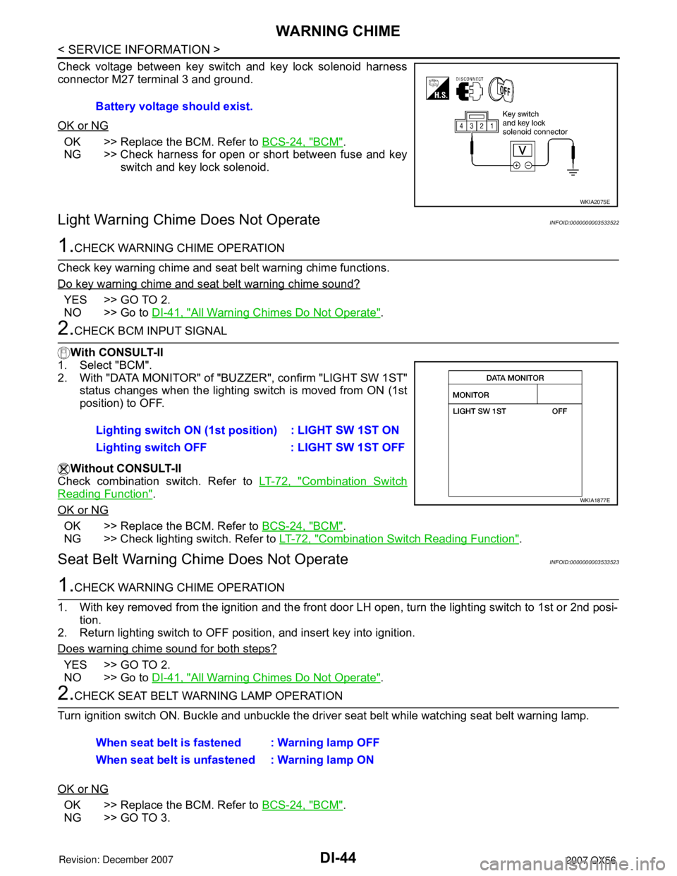
Check voltage between key switch and key lock solenoid harness
connector M27 terminal 3 and ground.
OK or NG
OK >> Replace the BCM. Refer to BCS-24, "BCM".
NG >> Check harness for open or short between fuse and key
switch and key lock solenoid.
Light Warning Chime Does Not OperateINFOID:0000000003533522
1.CHECK WARNING CHIME OPERATION
Check key warning chime and seat belt warning chime functions.
Do key warning chime and seat belt warning chime sound?
YES >> GO TO 2.
NO >> Go to DI-41, "
All Warning Chimes Do Not Operate".
2.CHECK BCM INPUT SIGNAL
With CONSULT-II
1. Select "BCM".
2. With "DATA MONITOR" of "BUZZER", confirm "LIGHT SW 1ST"
status changes when the lighting switch is moved from ON (1st
position) to OFF.
Without CONSULT-II
Check combination switch. Refer to LT-72, "
Combination Switch
Reading Function".
OK or NG
OK >> Replace the BCM. Refer to BCS-24, "BCM".
NG >> Check lighting switch. Refer to LT-72, "
Combination Switch Reading Function".
Seat Belt Warning Chime Does Not OperateINFOID:0000000003533523
1.CHECK WARNING CHIME OPERATION
1. With key removed from the ignition and the front door LH open, turn the lighting switch to 1st or 2nd posi-
tion.
2. Return lighting switch to OFF position, and insert key into ignition.
Does warning chime sound for both steps?
YES >> GO TO 2.
NO >> Go to DI-41, "
All Warning Chimes Do Not Operate".
2.CHECK SEAT BELT WARNING LAMP OPERATION
Turn ignition switch ON. Buckle and unbuckle the driver seat belt while watching seat belt warning lamp.
OK or NG
OK >> Replace the BCM. Refer to BCS-24, "BCM".
NG >> GO TO 3.Battery voltage should exist.
WKIA2075E
Lighting switch ON (1st position) : LIGHT SW 1ST ON
Lighting switch OFF : LIGHT SW 1ST OFF
WKIA1877E
When seat belt is fastened : Warning lamp OFF
When seat belt is unfastened : Warning lamp ON
Page 1976 of 3061
GI-10
< SERVICE INFORMATION >
HOW TO USE THIS MANUAL
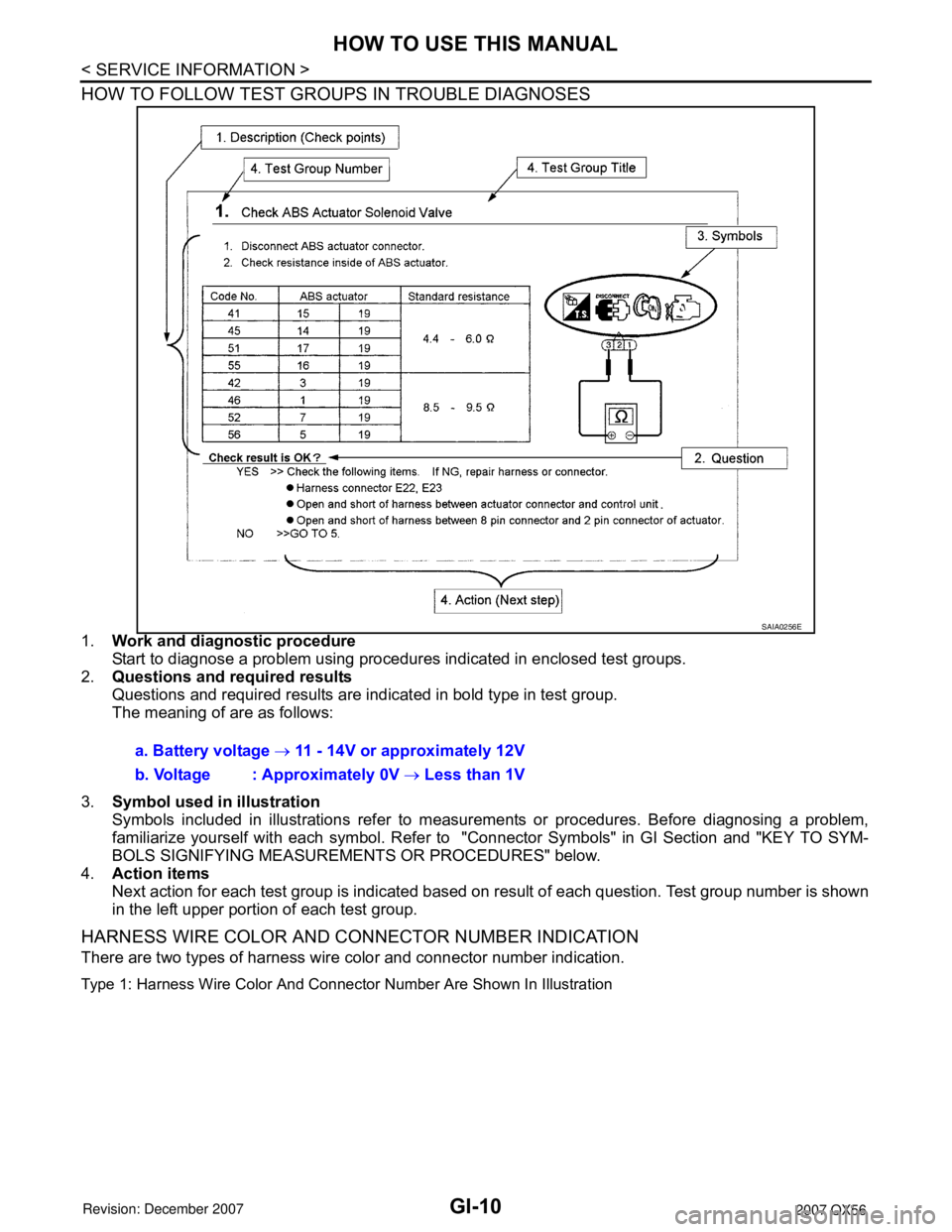
HOW TO FOLLOW TEST GROUPS IN TROUBLE DIAGNOSES
1.Work and diagnostic procedure
Start to diagnose a problem using procedures indicated in enclosed test groups.
2.Questions and required results
Questions and required results are indicated in bold type in test group.
The meaning of are as follows:
3.Symbol used in illustration
Symbols included in illustrations refer to measurements or procedures. Before diagnosing a problem,
familiarize yourself with each symbol. Refer to "Connector Symbols" in GI Section and "KEY TO SYM-
BOLS SIGNIFYING MEASUREMENTS OR PROCEDURES" below.
4.Action items
Next action for each test group is indicated based on result of each question. Test group number is shown
in the left upper portion of each test group.
HARNESS WIRE COLOR AND CONNECTOR NUMBER INDICATION
There are two types of harness wire color and connector number indication.
Type 1: Harness Wire Color And Connector Number Are Shown In Illustration
SAIA0256E
a. Battery voltage → 11 - 14V or approximately 12V
b. Voltage : Approximately 0V → Less than 1V
Page 1995 of 3061
SERVICE INFORMATION FOR ELECTRICAL INCIDENT
GI-29
< SERVICE INFORMATION >
C
D
E
F
G
H
I
J
K
L
MB
GI
N
O
P
• Close the relay and probe at the solenoid.
voltage; open is further down the circuit than the solenoid.
no voltage; open is between relay and solenoid (point C).
Any powered circuit can be diagnosed using the approach in the previous example.
Testing for “Shorts” in the Circuit
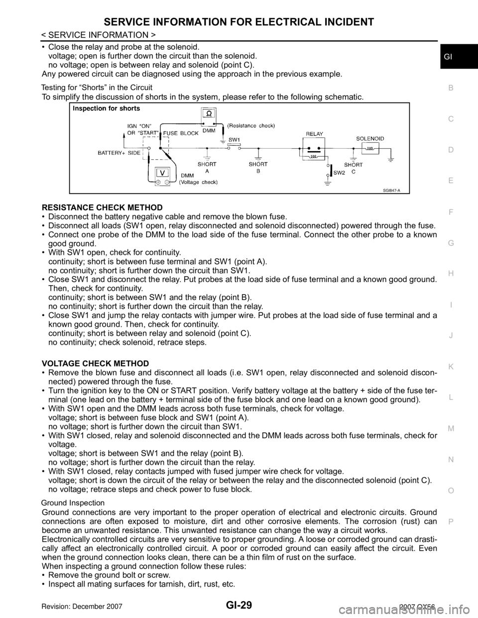
To simplify the discussion of shorts in the system, please refer to the following schematic.
RESISTANCE CHECK METHOD
• Disconnect the battery negative cable and remove the blown fuse.
• Disconnect all loads (SW1 open, relay disconnected and solenoid disconnected) powered through the fuse.
• Connect one probe of the DMM to the load side of the fuse terminal. Connect the other probe to a known
good ground.
• With SW1 open, check for continuity.
continuity; short is between fuse terminal and SW1 (point A).
no continuity; short is further down the circuit than SW1.
• Close SW1 and disconnect the relay. Put probes at the load side of fuse terminal and a known good ground.
Then, check for continuity.
continuity; short is between SW1 and the relay (point B).
no continuity; short is further down the circuit than the relay.
• Close SW1 and jump the relay contacts with jumper wire. Put probes at the load side of fuse terminal and a
known good ground. Then, check for continuity.
continuity; short is between relay and solenoid (point C).
no continuity; check solenoid, retrace steps.
VOLTAGE CHECK METHOD
• Remove the blown fuse and disconnect all loads (i.e. SW1 open, relay disconnected and solenoid discon-
nected) powered through the fuse.
• Turn the ignition key to the ON or START position. Verify battery voltage at the battery + side of the fuse ter-
minal (one lead on the battery + terminal side of the fuse block and one lead on a known good ground).
• With SW1 open and the DMM leads across both fuse terminals, check for voltage.
voltage; short is between fuse block and SW1 (point A).
no voltage; short is further down the circuit than SW1.
• With SW1 closed, relay and solenoid disconnected and the DMM leads across both fuse terminals, check for
voltage.
voltage; short is between SW1 and the relay (point B).
no voltage; short is further down the circuit than the relay.
• With SW1 closed, relay contacts jumped with fused jumper wire check for voltage.
voltage; short is down the circuit of the relay or between the relay and the disconnected solenoid (point C).
no voltage; retrace steps and check power to fuse block.
Ground Inspection
Ground connections are very important to the proper operation of electrical and electronic circuits. Ground
connections are often exposed to moisture, dirt and other corrosive elements. The corrosion (rust) can
become an unwanted resistance. This unwanted resistance can change the way a circuit works.
Electronically controlled circuits are very sensitive to proper grounding. A loose or corroded ground can drasti-
cally affect an electronically controlled circuit. A poor or corroded ground can easily affect the circuit. Even
when the ground connection looks clean, there can be a thin film of rust on the surface.
When inspecting a ground connection follow these rules:
• Remove the ground bolt or screw.
• Inspect all mating surfaces for tarnish, dirt, rust, etc.
SGI847-A
Page 2048 of 3061
POWER WINDOW SYSTEM
GW-29
< SERVICE INFORMATION >
C
D
E
F
G
H
J
K
L
MA
B
GW
N
O
P
outINFOID:0000000003533029
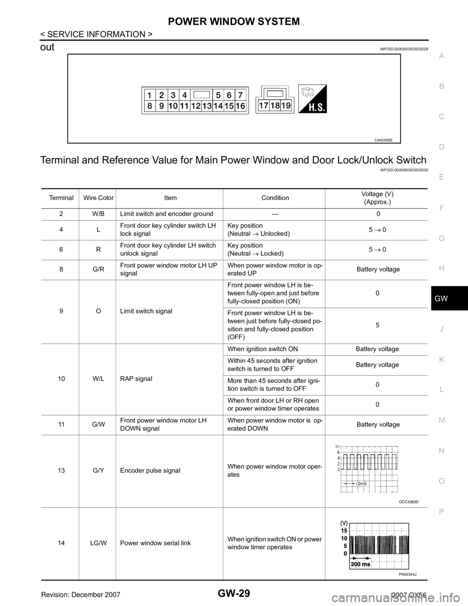
Terminal and Reference Value for Main Power Window and Door Lock/Unlock Switch
INFOID:0000000003533030
LIIA2455E
Terminal Wire Color Item ConditionVoltage (V)
(Approx.)
2 W/B Limit switch and encoder ground — 0
4LFront door key cylinder switch LH
lock signalKey position
(Neutral → Unlocked)5 → 0
6RFront door key cylinder LH switch
unlock signalKey position
(Neutral → Locked)5 → 0
8G/RFront power window motor LH UP
signalWhen power window motor is op-
erated UP Battery voltage
9 O Limit switch signalFront power window LH is be-
tween fully-open and just before
fully-closed position (ON)0
Front power window LH is be-
tween just before fully-closed po-
sition and fully-closed position
(OFF)5
10 W/L RAP signalWhen ignition switch ON Battery voltage
Within 45 seconds after ignition
switch is turned to OFFBattery voltage
More than 45 seconds after igni-
tion switch is turned to OFF0
When front door LH or RH open
or power window timer operates0
11 G / WFront power window motor LH
DOWN signalWhen power window motor is op-
erated DOWN Battery voltage
13 G/Y Encoder pulse signalWhen power window motor oper-
ates
14 LG/W Power window serial linkWhen ignition switch ON or power
window timer operates
OCC3383D
PIIA2344J
Page 2053 of 3061
GW-34
< SERVICE INFORMATION >
POWER WINDOW SYSTEM
BCM Power Supply and Ground Circuit Inspection
INFOID:0000000003533037
Refer to BCS-15, "BCM Power Supply and Ground Circuit Inspection".
Main Power Window and Door Lock/Unlock Switch Power Supply and Ground Circuit
Inspection
INFOID:0000000003533038
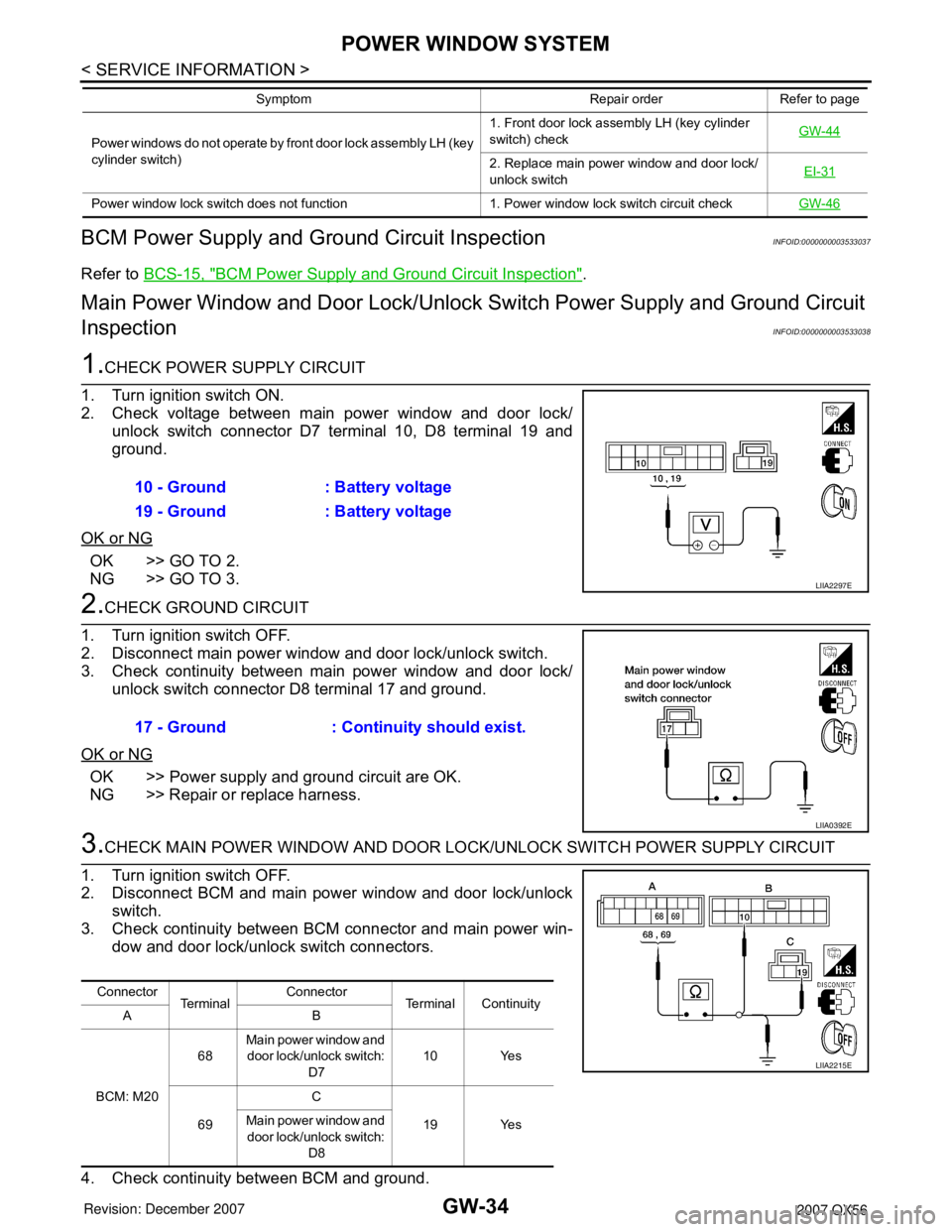
1.CHECK POWER SUPPLY CIRCUIT
1. Turn ignition switch ON.
2. Check voltage between main power window and door lock/
unlock switch connector D7 terminal 10, D8 terminal 19 and
ground.
OK or NG
OK >> GO TO 2.
NG >> GO TO 3.
2.CHECK GROUND CIRCUIT
1. Turn ignition switch OFF.
2. Disconnect main power window and door lock/unlock switch.
3. Check continuity between main power window and door lock/
unlock switch connector D8 terminal 17 and ground.
OK or NG
OK >> Power supply and ground circuit are OK.
NG >> Repair or replace harness.
3.CHECK MAIN POWER WINDOW AND DOOR LOCK/UNLOCK SWITCH POWER SUPPLY CIRCUIT
1. Turn ignition switch OFF.
2. Disconnect BCM and main power window and door lock/unlock
switch.
3. Check continuity between BCM connector and main power win-
dow and door lock/unlock switch connectors.
4. Check continuity between BCM and ground.
Power windows do not operate by front door lock assembly LH (key
cylinder switch)1. Front door lock assembly LH (key cylinder
switch) checkGW-44
2. Replace main power window and door lock/
unlock switchEI-31
Power window lock switch does not function 1. Power window lock switch circuit checkGW-46
Symptom Repair order Refer to page
10 - Ground : Battery voltage
19 - Ground : Battery voltage
LIIA2297E
17 - Ground : Continuity should exist.
LIIA0392E
Connector
Te r m i n a lConnector
Terminal Continuity
AB
BCM: M2068Main power window and
door lock/unlock switch:
D710 Yes
69C
19 Yes Main power window and
door lock/unlock switch:
D8
LIIA2215E
Page 2063 of 3061
GW-44
< SERVICE INFORMATION >
POWER WINDOW SYSTEM
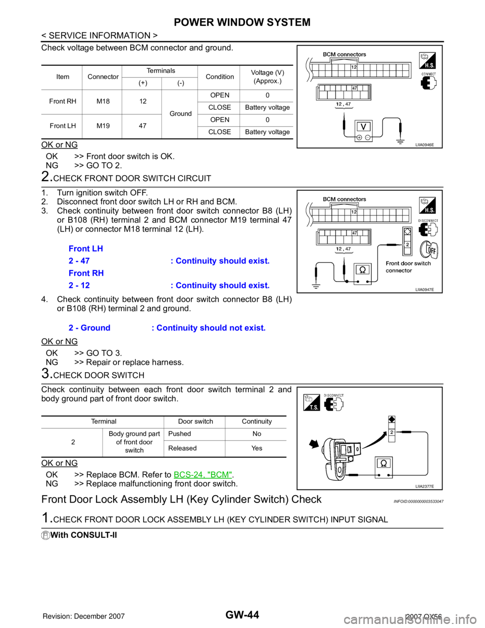
Check voltage between BCM connector and ground.
OK or NG
OK >> Front door switch is OK.
NG >> GO TO 2.
2.CHECK FRONT DOOR SWITCH CIRCUIT
1. Turn ignition switch OFF.
2. Disconnect front door switch LH or RH and BCM.
3. Check continuity between front door switch connector B8 (LH)
or B108 (RH) terminal 2 and BCM connector M19 terminal 47
(LH) or connector M18 terminal 12 (LH).
4. Check continuity between front door switch connector B8 (LH)
or B108 (RH) terminal 2 and ground.
OK or NG
OK >> GO TO 3.
NG >> Repair or replace harness.
3.CHECK DOOR SWITCH
Check continuity between each front door switch terminal 2 and
body ground part of front door switch.
OK or NG
OK >> Replace BCM. Refer to BCS-24, "BCM".
NG >> Replace malfunctioning front door switch.
Front Door Lock Assembly LH (Key Cylinder Switch) CheckINFOID:0000000003533047
1.CHECK FRONT DOOR LOCK ASSEMBLY LH (KEY CYLINDER SWITCH) INPUT SIGNAL
With CONSULT-II
Item ConnectorTe r m i n a l s
ConditionVoltage (V)
(Approx.)
(+) (-)
Front RH M18 12
GroundOPEN 0
CLOSE Battery voltage
Front LH M19 47OPEN 0
CLOSE Battery voltage
LIIA0946E
Front LH
2 - 47 : Continuity should exist.
Front RH
2 - 12 : Continuity should exist.
2 - Ground : Continuity should not exist.
LIIA0947E
Terminal Door switch Continuity
2Body ground part
of front door
switchPushed No
Released Yes
LIIA2377E
Page 2310 of 3061

INTERIOR ROOM LAMP
LT-103
< SERVICE INFORMATION >
C
D
E
F
G
H
I
J
L
MA
B
LT
N
O
P
• through grounds M57, M61 and M79.
When a signal, or combination of signals is received by BCM, ground is supplied
• through BCM terminal 63
• to door mirror LH and RH terminal 13
• to front room/map lamp assembly terminal 1
• through front room/map lamp assembly terminal 2
• to personal lamps terminal 1, and
• through BCM terminal 49
• to cargo lamp terminal 1.
With power and ground supplied, the lamps illuminate.
SWITCH OPERATION
When any door switch is ON (door is opened), ground is supplied
• to front and rear step lamps LH and RH and foot lamp LH and RH terminal –
• through BCM terminal 62.
And power is supplied
• through BCM terminal 56
• to front and rear step lamps LH and RH terminal +
• to ignition keyhole illumination terminal +
• to door mirror LH and RH terminal 12
• to front room/map lamp assembly terminal 6
• to vanity lamp LH and RH terminal 1
• to personal lamp 2nd row and 3rd row terminal 3
• to cargo lamp terminal 2, and
• to foot lamp LH and RH terminal +.
When map lamp switch is ON, ground is supplied
• to front room/map lamp assembly terminal 5
• through grounds M57, M61 and M79.
When vanity lamp (LH and RH) is ON, ground is supplied
• to vanity lamp (LH and RH) terminal 2
• through grounds M57, M61 and M79.
When cargo lamp is ON, ground is supplied through cargo lamp case ground.
ROOM LAMP TIMER OPERATION
When lamp switch is in DOOR position and all conditions below are met, BCM performs timer control (maxi-
mum 30 seconds) for interior room lamp and map lamp ON/OFF.
Power is supplied
• through 10A fuse [No. 19, located in the fuse block (J/B)]
• to key switch and key lock solenoid terminal 3.
Key is removed from ignition key cylinder (key switch OFF), power will not be supplied to BCM terminal 37.
Serial data is supplied
• to BCM terminal 22
• through main power window and door lock/unlock switch terminal 14.
At the time that front door LH is opened, BCM detects that front door LH is unlocked. It determines that interior
room lamp and map lamp timer operation conditions are met, and turns the interior room lamps ON for 30 sec-
onds.
Key is in ignition key cylinder (key switch ON), power is supplied
• through key switch and key lock solenoid terminal 4
• to BCM terminal 37.
When key is removed from key switch and key lock solenoid (key switch OFF), power supply to BCM terminal
37 is terminated. BCM detects that key has been removed, determines that interior room lamp and map lamp
timer conditions are met, and turns the interior room lamps ON for 30 seconds.
When front door LH opens → closes, and the key is not inserted in the key switch and key lock solenoid (key
switch OFF), BCM terminal 47 changes between 0V (door open) → 12V (door closed). The BCM determines
that conditions for interior room lamp operation are met and turns the interior room lamp ON for 30 seconds.
Timer control is canceled under the following conditions.
• Front door LH is locked [when locked by keyfob, main power window and door lock/unlock switch, or front
door lock assembly LH (key cylinder switch)]
• Front door LH is opened (front door switch LH turns ON)
• Ignition switch ON.
INTERIOR LAMP BATTERY SAVER CONTROL
Page 2311 of 3061

LT-104
< SERVICE INFORMATION >
INTERIOR ROOM LAMP
If interior lamp is left “ON”, it will not be turned off even when door is closed.
BCM turns off interior lamp automatically to save battery 30 minutes after ignition switch is turned off.
BCM controls interior lamps listed below:
• Vanity lamp
• Room/map lamp
• Cargo lamp
• Personal lamp
• Step lamps
• Puddle lamps
• Foot lamps
• Ignition keyhole illumination
After lamps turn OFF by the battery saver system, the lamps illuminate again when
• signal received from keyfob, or main power window and door lock/unlock switch or front door lock assembly
LH (key cylinder switch) is locked or unlocked
• door is opened or closed
• key is removed from ignition key cylinder (key switch OFF) or inserted in ignition key cylinder (key switch
ON).
Interior lamp battery saver control period can be changed by the function setting of CONSULT-II.