2007 INFINITI QX56 fuel
[x] Cancel search: fuelPage 1098 of 3061
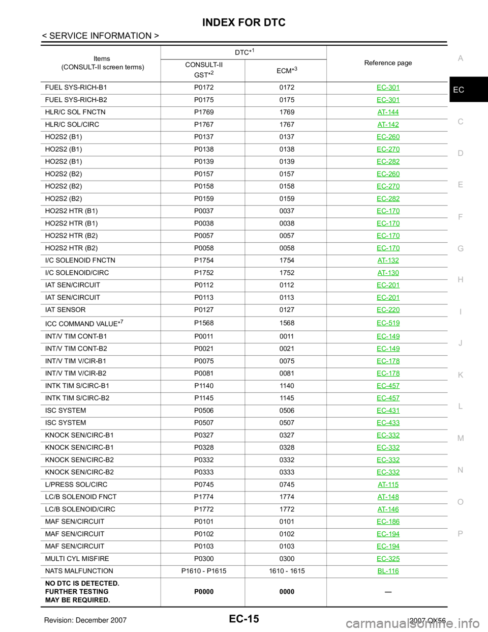
INDEX FOR DTC
EC-15
< SERVICE INFORMATION >
C
D
E
F
G
H
I
J
K
L
MA
EC
N
P OFUEL SYS-RICH-B1 P0172 0172EC-301
FUEL SYS-RICH-B2 P0175 0175EC-301
HLR/C SOL FNCTN P1769 1769AT- 1 4 4
HLR/C SOL/CIRC P1767 1767AT- 1 4 2
HO2S2 (B1) P0137 0137EC-260
HO2S2 (B1) P0138 0138EC-270
HO2S2 (B1) P0139 0139EC-282
HO2S2 (B2) P0157 0157EC-260
HO2S2 (B2) P0158 0158EC-270
HO2S2 (B2) P0159 0159EC-282
HO2S2 HTR (B1) P0037 0037EC-170
HO2S2 HTR (B1) P0038 0038EC-170
HO2S2 HTR (B2) P0057 0057EC-170
HO2S2 HTR (B2) P0058 0058EC-170
I/C SOLENOID FNCTN P1754 1754AT- 1 3 2
I/C SOLENOID/CIRC P1752 1752AT- 1 3 0
IAT SEN/CIRCUIT P0112 0112EC-201
IAT SEN/CIRCUIT P0113 0113EC-201
IAT SENSOR P0127 0127EC-220
ICC COMMAND VALUE*7P1568 1568EC-519
INT/V TIM CONT-B1 P0011 0011EC-149
INT/V TIM CONT-B2 P0021 0021EC-149
INT/V TIM V/CIR-B1 P0075 0075EC-178
INT/V TIM V/CIR-B2 P0081 0081EC-178
INTK TIM S/CIRC-B1 P1140 1140EC-457
INTK TIM S/CIRC-B2 P1145 1145EC-457
ISC SYSTEM P0506 0506EC-431
ISC SYSTEM P0507 0507EC-433
KNOCK SEN/CIRC-B1 P0327 0327EC-332
KNOCK SEN/CIRC-B1 P0328 0328EC-332
KNOCK SEN/CIRC-B2 P0332 0332EC-332
KNOCK SEN/CIRC-B2 P0333 0333EC-332
L/PRESS SOL/CIRC P0745 0745AT- 11 5
LC/B SOLENOID FNCT P1774 1774AT- 1 4 8
LC/B SOLENOID/CIRC P1772 1772AT- 1 4 6
MAF SEN/CIRCUIT P0101 0101EC-186
MAF SEN/CIRCUIT P0102 0102EC-194
MAF SEN/CIRCUIT P0103 0103EC-194
MULTI CYL MISFIRE P0300 0300EC-325
NATS MALFUNCTION P1610 - P1615 1610 - 1615BL-116
NO DTC IS DETECTED.
FURTHER TESTING
MAY BE REQUIRED.P0000 0000 — Items
(CONSULT-II screen terms)DTC*
1
Reference page
CONSULT-II
GST*
2ECM*3
Page 1100 of 3061
PRECAUTIONS
EC-17
< SERVICE INFORMATION >
C
D
E
F
G
H
I
J
K
L
MA
EC
N
P O
PRECAUTIONS
Precaution for Supplemental Restraint System (SRS) "AIR BAG" and "SEAT BELT
PRE-TENSIONER"
INFOID:0000000003531580
The Supplemental Restraint System such as “AIR BAG” and “SEAT BELT PRE-TENSIONER”, used along
with a front seat belt, helps to reduce the risk or severity of injury to the driver and front passenger for certain
types of collision. This system includes seat belt switch inputs and dual stage front air bag modules. The SRS
system uses the seat belt switches to determine the front air bag deployment, and may only deploy one front
air bag, depending on the severity of a collision and whether the front occupants are belted or unbelted.
Information necessary to service the system safely is included in the SRS and SB section of this Service Man-
ual.
WARNING:
• To avoid rendering the SRS inoperative, which could increase the risk of personal injury or death in
the event of a collision which would result in air bag inflation, all maintenance must be performed by
an authorized NISSAN/INFINITI dealer.
• Improper maintenance, including incorrect removal and installation of the SRS, can lead to personal
injury caused by unintentional activation of the system. For removal of Spiral Cable and Air Bag
Module, see the SRS section.
• Do not use electrical test equipment on any circuit related to the SRS unless instructed to in this
Service Manual. SRS wiring harnesses can be identified by yellow and/or orange harnesses or har-
ness connectors.
On Board Diagnosis (OBD) System of Engine and A/TINFOID:0000000003531581
The ECM has an on board diagnostic system. It will light up the malfunction indicator lamp (MIL) to warn the
driver of a malfunction causing emission deterioration.
CAUTION:
• Be sure to turn the ignition switch OFF and disconnect the negative battery cable before any repair
or inspection work. The open/short circuit of related switches, sensors, solenoid valves, etc. will
cause the MIL to light up.
• Be sure to connect and lock the connectors securely after work. A loose (unlocked) connector will
cause the MIL to light up due to the open circuit. (Be sure the connector is free from water, grease,
dirt, bent terminals, etc.)
• Certain systems and components, especially those related to OBD, may use a new style slide-lock-
ing type harness connector. For description and how to disconnect, refer to PG-66
.
• Be sure to route and secure the harnesses properly after work. The interference of the harness with
a bracket, etc. may cause the MIL to light up due to the short circuit.
• Be sure to connect rubber tubes properly after work. A misconnected or disconnected rubber tube
may cause the MIL to light up due to the malfunction of the EVAP system or fuel injection system,
etc.
• Be sure to erase the unnecessary malfunction information (repairs completed) from the ECM and
TCM (Transmission control module) before returning the vehicle to the customer.
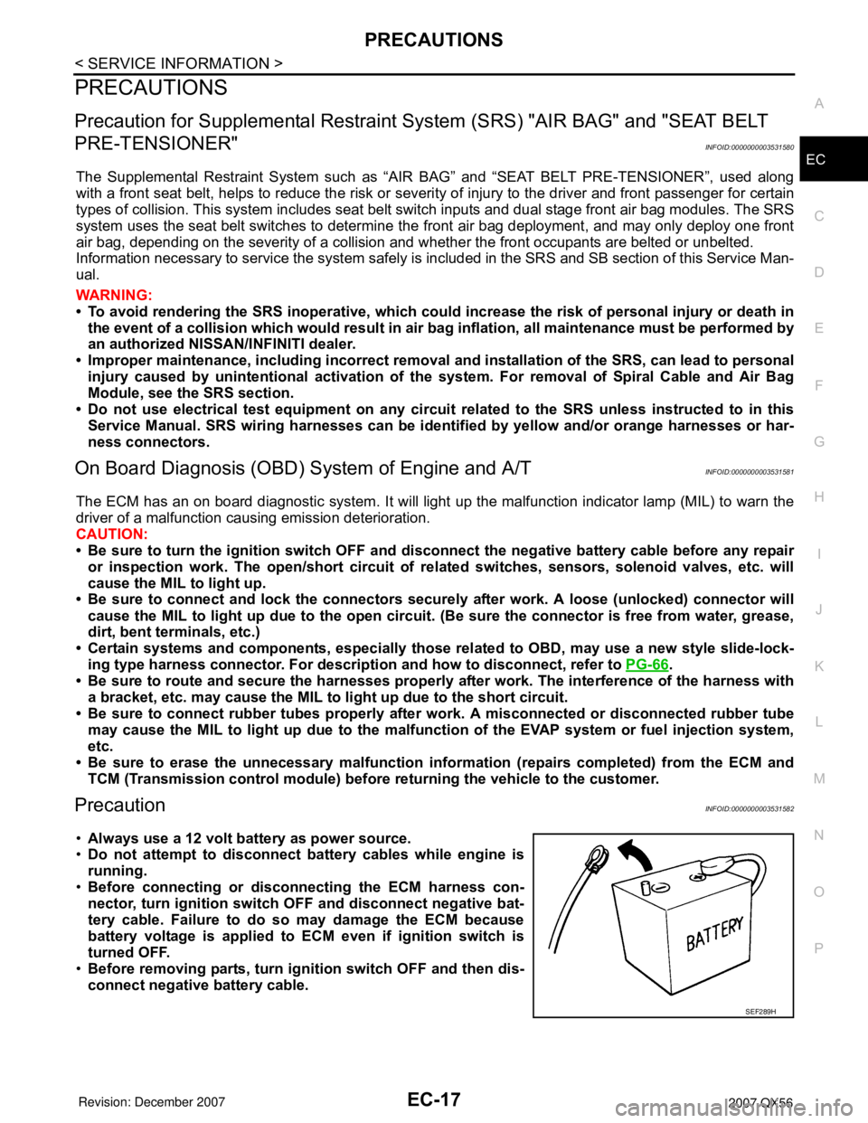
PrecautionINFOID:0000000003531582
•Always use a 12 volt battery as power source.
•Do not attempt to disconnect battery cables while engine is
running.
•Before connecting or disconnecting the ECM harness con-
nector, turn ignition switch OFF and disconnect negative bat-
tery cable. Failure to do so may damage the ECM because
battery voltage is applied to ECM even if ignition switch is
turned OFF.
•Before removing parts, turn ignition switch OFF and then dis-
connect negative battery cable.
SEF289H
Page 1103 of 3061
EC-20
< SERVICE INFORMATION >
PRECAUTIONS
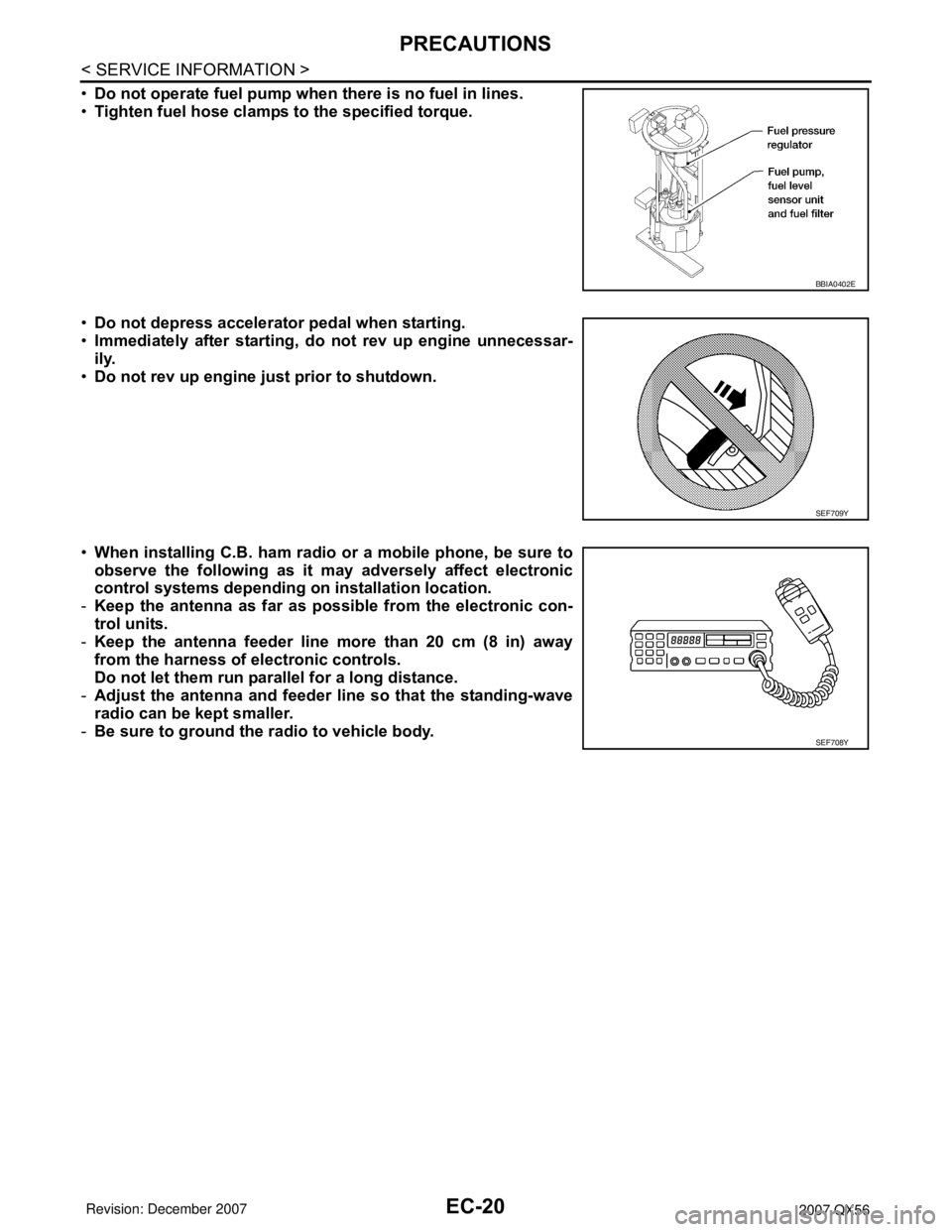
•Do not operate fuel pump when there is no fuel in lines.
•Tighten fuel hose clamps to the specified torque.
•Do not depress accelerator pedal when starting.
•Immediately after starting, do not rev up engine unnecessar-
ily.
•Do not rev up engine just prior to shutdown.
•When installing C.B. ham radio or a mobile phone, be sure to
observe the following as it may adversely affect electronic
control systems depending on installation location.
-Keep the antenna as far as possible from the electronic con-
trol units.
-Keep the antenna feeder line more than 20 cm (8 in) away
from the harness of electronic controls.
Do not let them run parallel for a long distance.
-Adjust the antenna and feeder line so that the standing-wave
radio can be kept smaller.
-Be sure to ground the radio to vehicle body.
BBIA0402E
SEF709Y
SEF708Y
Page 1104 of 3061
PREPARATION
EC-21
< SERVICE INFORMATION >
C
D
E
F
G
H
I
J
K
L
MA
EC
N
P O
PREPARATION
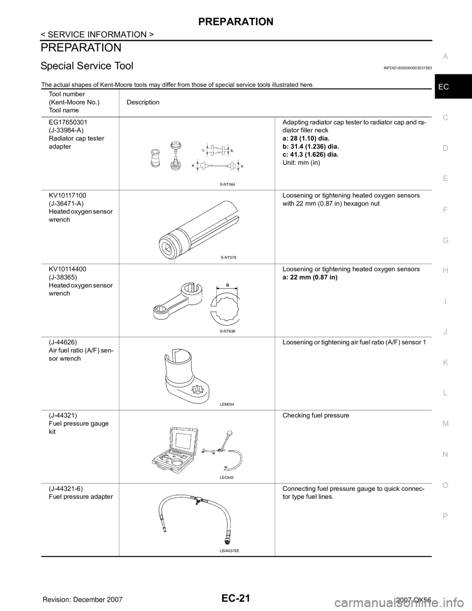
Special Service ToolINFOID:0000000003531583
The actual shapes of Kent-Moore tools may differ from those of special service tools illustrated here.
Tool number
(Kent-Moore No.)
Tool nameDescription
EG17650301
(J-33984-A)
Radiator cap tester
adapterAdapting radiator cap tester to radiator cap and ra-
diator filler neck
a: 28 (1.10) dia.
b: 31.4 (1.236) dia.
c: 41.3 (1.626) dia.
Unit: mm (in)
KV10117100
(J-36471-A)
Heated oxygen sensor
wrenchLoosening or tightening heated oxygen sensors
with 22 mm (0.87 in) hexagon nut
KV10114400
(J-38365)
Heated oxygen sensor
wrenchLoosening or tightening heated oxygen sensors
a: 22 mm (0.87 in)
(J-44626)
Air fuel ratio (A/F) sen-
sor wrenchLoosening or tightening air fuel ratio (A/F) sensor 1
(J-44321)
Fuel pressure gauge
kitChecking fuel pressure
(J-44321-6)
Fuel pressure adapterConnecting fuel pressure gauge to quick connec-
tor type fuel lines.
S-NT564
S-NT379
S-NT636
LEM054
LEC642
LBIA0376E
Page 1105 of 3061
EC-22
< SERVICE INFORMATION >
PREPARATION
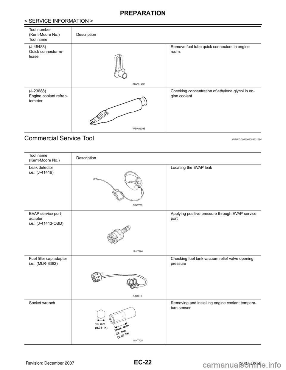
Commercial Service Tool
INFOID:0000000003531584
(J-45488)
Quick connector re-
leaseRemove fuel tube quick connectors in engine
room.
(J-23688)
Engine coolant refrac-
tometerChecking concentration of ethylene glycol in en-
gine coolant Tool number
(Kent-Moore No.)
Tool nameDescription
PBIC0198E
WBIA0539E
Tool name
(Kent-Moore No.)Description
Leak detector
i.e.: (J-41416)Locating the EVAP leak
EVAP service port
adapter
i.e.: (J-41413-OBD)Applying positive pressure through EVAP service
port
Fuel filler cap adapter
i.e.: (MLR-8382)Checking fuel tank vacuum relief valve opening
pressure
Socket wrench Removing and installing engine coolant tempera-
ture sensor
S-NT703
S-NT704
S-NT815
S-NT705
Page 1107 of 3061
EC-24
< SERVICE INFORMATION >
ENGINE CONTROL SYSTEM
ENGINE CONTROL SYSTEM
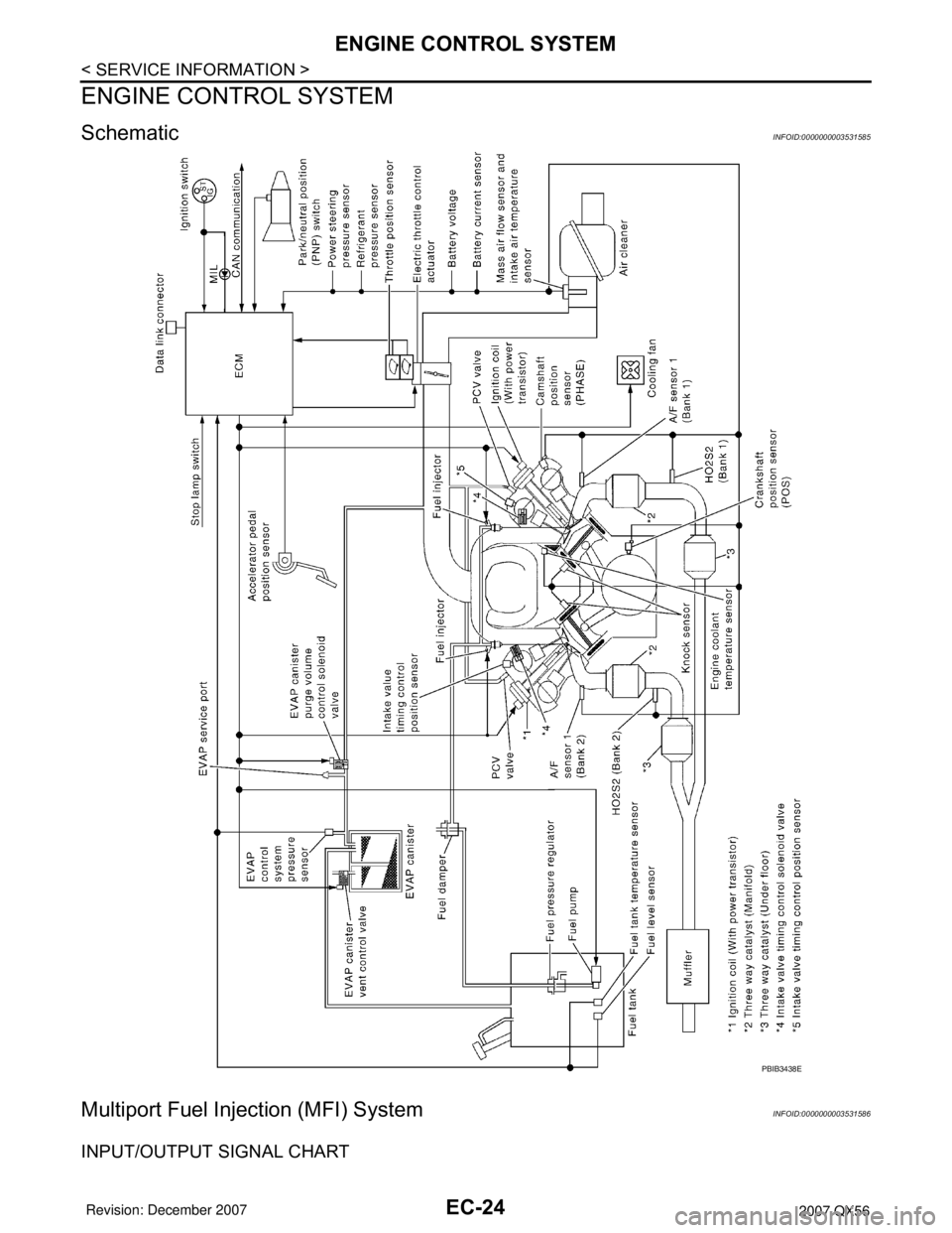
SchematicINFOID:0000000003531585
Multiport Fuel Injection (MFI) SystemINFOID:0000000003531586
INPUT/OUTPUT SIGNAL CHART
PBIB3438E
Page 1108 of 3061
ENGINE CONTROL SYSTEM
EC-25
< SERVICE INFORMATION >
C
D
E
F
G
H
I
J
K
L
MA
EC
N
P O
*1: This sensor is not used to control the engine system. This is used only for the on board diagnosis.
*2: This signal is sent to the ECM through CAN communication line.
*3: ECM determines the start signal status by the signals of engine speed and battery voltage.
SYSTEM DESCRIPTION
The amount of fuel injected from the fuel injector is determined by the ECM. The ECM controls the length of
time the valve remains open (injection pulse duration). The amount of fuel injected is a program value in the
ECM memory. The program value is preset by engine operating conditions. These conditions are determined
by input signals (for engine speed and intake air) from both the crankshaft position sensor and the mass air
flow sensor.
VARIOUS FUEL INJECTION INCREASE/DECREASE COMPENSATION
In addition, the amount of fuel injected is compensated to improve engine performance under various operat-
ing conditions as listed below.
• When starting the engine
• During acceleration
• Hot-engine operation
• When selector lever is changed from N to D
• High-load, high-speed operation
• During deceleration
• During high engine speed operation
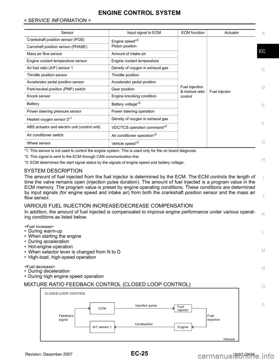
MIXTURE RATIO FEEDBACK CONTROL (CLOSED LOOP CONTROL)
Sensor Input signal to ECM ECM function Actuator
Crankshaft position sensor (POS)
Engine speed*
3
Piston position
Fuel injection
& mixture ratio
controlFuel injector Camshaft position sensor (PHASE)
Mass air flow sensor Amount of intake air
Engine coolant temperature sensor Engine coolant temperature
Air fuel ratio (A/F) sensor 1 Density of oxygen in exhaust gas
Throttle position sensor Throttle position
Accelerator pedal position sensor Accelerator pedal position
Park/neutral position (PNP) switch Gear position
Knock sensor Engine knocking condition
Battery
Battery voltage*
3
Power steering pressure sensor Power steering operation
Heated oxygen sensor 2*
1Density of oxygen in exhaust gas
ABS actuator and electric unit (control unit)
VDC/TCS operation command*
2
Air conditioner switch
Air conditioner operation*2
Wheel sensor
Vehicle speed*2
PBIB3020E
Page 1109 of 3061
EC-26
< SERVICE INFORMATION >
ENGINE CONTROL SYSTEM
The mixture ratio feedback system provides the best air-fuel mixture ratio for driveability and emission control.
The three way catalyst (manifold) can then better reduce CO, HC and NOx emissions. This system uses air
fuel ratio (A/F) sensor 1 in the exhaust manifold to monitor whether the engine operation is rich or lean. The
ECM adjusts the injection pulse width according to the sensor voltage signal. For more information about air
fuel ratio (A/F) sensor 1, refer to EC-225
. This maintains the mixture ratio within the range of stoichiometric
(ideal air-fuel mixture).
This stage is referred to as the closed loop control condition.
Heated oxygen sensor 2 is located downstream of the three way catalyst (manifold). Even if the switching
characteristics of air fuel ratio (A/F) sensor 1 shift, the air-fuel ratio is controlled to stoichiometric by the signal
from heated oxygen sensor 2.
Open Loop Control
The open loop system condition refers to when the ECM detects any of the following conditions. Feedback
control stops in order to maintain stabilized fuel combustion.
• Deceleration and acceleration
• High-load, high-speed operation
• Malfunction of A/F sensor 1 or its circuit
• Insufficient activation of A/F sensor 1 at low engine coolant temperature
• High engine coolant temperature
• During warm-up
• After shifting from N to D
• When starting the engine
MIXTURE RATIO SELF-LEARNING CONTROL
The mixture ratio feedback control system monitors the mixture ratio signal transmitted from A/F sensor 1.
This feedback signal is then sent to the ECM. The ECM controls the basic mixture ratio as close to the theoret-
ical mixture ratio as possible. However, the basic mixture ratio is not necessarily controlled as originally
designed. Both manufacturing differences (i.e., mass air flow sensor hot wire) and characteristic changes dur-
ing operation (i.e., injector clogging) directly affect mixture ratio.
Accordingly, the difference between the basic and theoretical mixture ratios is monitored in this system. This is
then computed in terms of “injection pulse duration” to automatically compensate for the difference between
the two ratios.
“Fuel trim” refers to the feedback compensation value compared against the basic injection duration. Fuel trim
includes short term fuel trim and long term fuel trim.
“Short term fuel trim” is the short-term fuel compensation used to maintain the mixture ratio at its theoretical
value. The signal from A/F sensor 1 indicates whether the mixture ratio is RICH or LEAN compared to the the-
oretical value. The signal then triggers a reduction in fuel volume if the mixture ratio is rich, and an increase in
fuel volume if it is lean.
“Long term fuel trim” is overall fuel compensation carried out long-term to compensate for continual deviation
of the short term fuel trim from the central value. Such deviation will occur due to individual engine differences,
wear over time and changes in the usage environment.
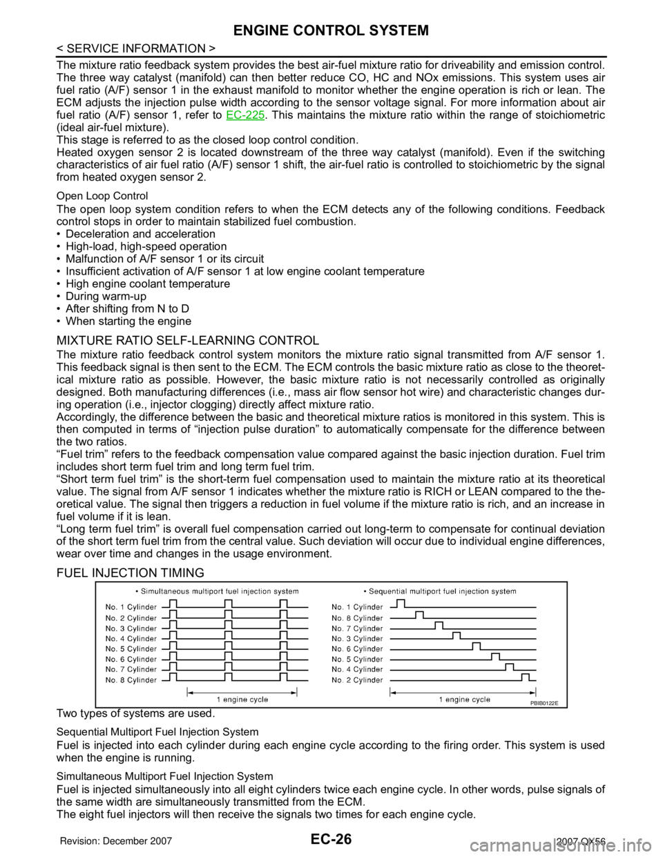
FUEL INJECTION TIMING
Two types of systems are used.
Sequential Multiport Fuel Injection System
Fuel is injected into each cylinder during each engine cycle according to the firing order. This system is used
when the engine is running.
Simultaneous Multiport Fuel Injection System
Fuel is injected simultaneously into all eight cylinders twice each engine cycle. In other words, pulse signals of
the same width are simultaneously transmitted from the ECM.
The eight fuel injectors will then receive the signals two times for each engine cycle.
PBIB0122E