2007 INFINITI QX56 change time
[x] Cancel search: change timePage 1366 of 3061

DTC P0139, P0159 HO2S2
EC-283
< SERVICE INFORMATION >
C
D
E
F
G
H
I
J
K
L
MA
EC
N
P O
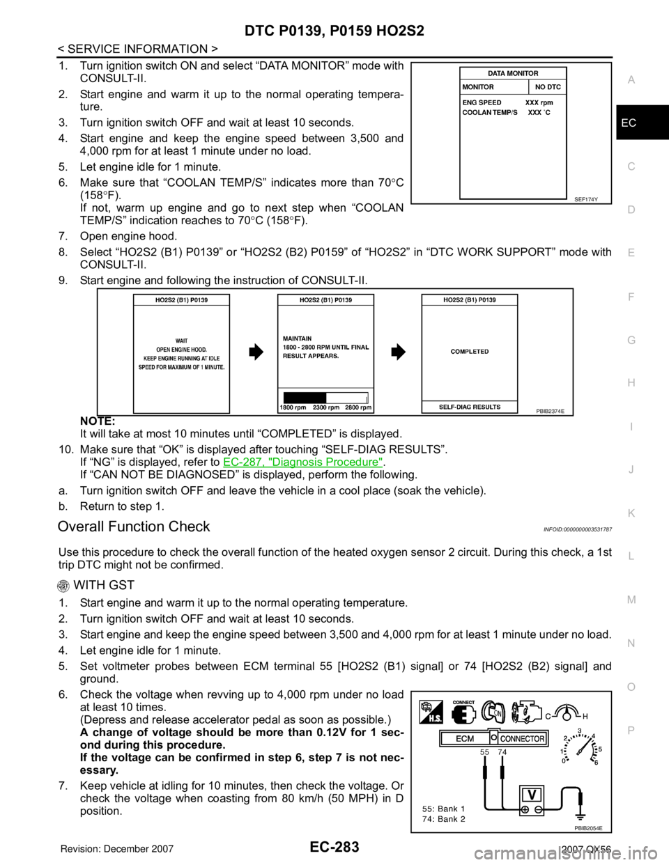
1. Turn ignition switch ON and select “DATA MONITOR” mode with
CONSULT-II.
2. Start engine and warm it up to the normal operating tempera-
ture.
3. Turn ignition switch OFF and wait at least 10 seconds.
4. Start engine and keep the engine speed between 3,500 and
4,000 rpm for at least 1 minute under no load.
5. Let engine idle for 1 minute.
6. Make sure that “COOLAN TEMP/S” indicates more than 70°C
(158°F).
If not, warm up engine and go to next step when “COOLAN
TEMP/S” indication reaches to 70°C (158°F).
7. Open engine hood.
8. Select “HO2S2 (B1) P0139” or “HO2S2 (B2) P0159” of “HO2S2” in “DTC WORK SUPPORT” mode with
CONSULT-II.
9. Start engine and following the instruction of CONSULT-II.
NOTE:
It will take at most 10 minutes until “COMPLETED” is displayed.
10. Make sure that “OK” is displayed after touching “SELF-DIAG RESULTS”.
If “NG” is displayed, refer to EC-287, "
Diagnosis Procedure".
If “CAN NOT BE DIAGNOSED” is displayed, perform the following.
a. Turn ignition switch OFF and leave the vehicle in a cool place (soak the vehicle).
b. Return to step 1.
Overall Function CheckINFOID:0000000003531787
Use this procedure to check the overall function of the heated oxygen sensor 2 circuit. During this check, a 1st
trip DTC might not be confirmed.
WITH GST
1. Start engine and warm it up to the normal operating temperature.
2. Turn ignition switch OFF and wait at least 10 seconds.
3. Start engine and keep the engine speed between 3,500 and 4,000 rpm for at least 1 minute under no load.
4. Let engine idle for 1 minute.
5. Set voltmeter probes between ECM terminal 55 [HO2S2 (B1) signal] or 74 [HO2S2 (B2) signal] and
ground.
6. Check the voltage when revving up to 4,000 rpm under no load
at least 10 times.
(Depress and release accelerator pedal as soon as possible.)
A change of voltage should be more than 0.12V for 1 sec-
ond during this procedure.
If the voltage can be confirmed in step 6, step 7 is not nec-
essary.
7. Keep vehicle at idling for 10 minutes, then check the voltage. Or
check the voltage when coasting from 80 km/h (50 MPH) in D
position.
SEF174Y
PBIB2374E
PBIB2054E
Page 1438 of 3061

DTC P0441 EVAP CONTROL SYSTEM
EC-355
< SERVICE INFORMATION >
C
D
E
F
G
H
I
J
K
L
MA
EC
N
P O
2. Turn ignition switch OFF and wait at least 10 seconds.
3. Start engine and let it idle for at least 70 seconds.
4. Select “PURG FLOW P0441” of “EVAPORATIVE SYSTEM” in “DTC CONFIRMATION” mode with CON-
SULT-II.
5. Touch “START”.
If “COMPLETED” is displayed, go to step 7.
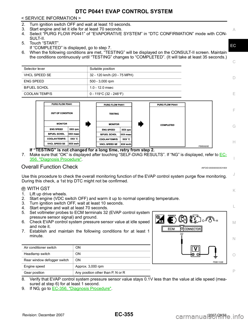
6. When the following conditions are met, “TESTING” will be displayed on the CONSULT-II screen. Maintain
the conditions continuously until “TESTING” changes to “COMPLETED”. (It will take at least 35 seconds.)
If “TESTING” is not changed for a long time, retry from step 2.
7. Make sure that “OK” is displayed after touching “SELF-DIAG RESULTS”. If “NG” is displayed, refer to EC-
356, "Diagnosis Procedure".
Overall Function CheckINFOID:0000000003531854
Use this procedure to check the overall monitoring function of the EVAP control system purge flow monitoring.
During this check, a 1st trip DTC might not be confirmed.
WITH GST
1. Lift up drive wheels.
2. Start engine (VDC switch OFF) and warm it up to normal operating temperature.
3. Turn ignition switch OFF, wait at least 10 seconds.
4. Start engine and wait at least 70 seconds.
5. Set voltmeter probes to ECM terminals 32 (EVAP control system
pressure sensor signal) and ground.
6. Check EVAP control system pressure sensor value at idle speed
and note it.
7. Establish and maintain the following conditions for at least 1
minute.
8. Verify that EVAP control system pressure sensor value stays 0.1V less than the value at idle speed (mea-
sured at step 6) for at least 1 second.
9. If NG, go to EC-356, "
Diagnosis Procedure".
Selector lever Suitable position
VHCL SPEED SE 32 - 120 km/h (20 - 75 MPH)
ENG SPEED 500 - 3,000 rpm
B/FUEL SCHDL 1.0 - 12.0 msec
COOLAN TEMP/S 0 - 119°C (32 - 246°F)
PBIB0826E
Air conditioner switch ON
Headlamp switch ON
Rear window defogger switch ON
Engine speed Approx. 3,000 rpm
Gear position Any position other than P, N or R
PBIB1109E
Page 1736 of 3061

SQUEAK AND RATTLE TROUBLE DIAGNOSIS
EI-7
< SERVICE INFORMATION >
C
D
E
F
G
H
J
K
L
MA
B
EI
N
O
P
Most of these incidents can be repaired by adjusting, securing or insulating the item(s) or component(s) caus-
ing the noise.
SUNROOF/HEADLINING
Noises in the sunroof/headlining area can often be traced to one of the following:
1. Sunroof lid, rail, linkage or seals making a rattle or light knocking noise
2. Sun visor shaft shaking in the holder
3. Front or rear windshield touching headliner and squeaking
Again, pressing on the components to stop the noise while duplicating the conditions can isolate most of these
incidents. Repairs usually consist of insulating with felt cloth tape.
OVERHEAD CONSOLE (FRONT AND REAR)
Overhead console noises are often caused by the console panel clips not being engaged correctly. Most of
these incidents are repaired by pushing up on the console at the clip locations until the clips engage.
In addition look for:
1. Loose harness or harness connectors.
2. Front console map/reading lamp lens loose.
3. Loose screws at console attachment points.
SEATS
When isolating seat noise it's important to note the position the seat is in and the load placed on the seat when
the noise is present. These conditions should be duplicated when verifying and isolating the cause of the
noise.
Cause of seat noise include:
1. Headrest rods and holder
2. A squeak between the seat pad cushion and frame
3. The rear seatback lock and bracket
These noises can be isolated by moving or pressing on the suspected components while duplicating the con-
ditions under which the noise occurs. Most of these incidents can be repaired by repositioning the component
or applying urethane tape to the contact area.
UNDERHOOD
Some interior noise may be caused by components under the hood or on the engine wall. The noise is then
transmitted into the passenger compartment.
Causes of transmitted underhood noise include:
1. Any component installed to the engine wall
2. Components that pass through the engine wall
3. Engine wall mounts and connectors
4. Loose radiator installation pins
5. Hood bumpers out of adjustment
6. Hood striker out of adjustment
These noises can be difficult to isolate since they cannot be reached from the interior of the vehicle. The best
method is to secure, move or insulate one component at a time and test drive the vehicle. Also, engine RPM
or load can be changed to isolate the noise. Repairs can usually be made by moving, adjusting, securing, or
insulating the component causing the noise.
Page 1826 of 3061

EM-56
< SERVICE INFORMATION >
CAMSHAFT
2. Perform the following procedure so as to prevent the engine from being unintentionally started while
checking.
a. Release fuel pressure. Refer to EC-80, "
Fuel Pressure Check".
b. Disconnect ignition coil and injector harness connectors if practical.
3. Remove IVT control solenoid valve.
4. Crank engine, and then make sure that engine oil comes out from IVT control cover oil hole. End cranking
after checking.
WARNING:
Be careful not to touch rotating parts (drive be lts, idler pulley, and crankshaft pulley, etc.).
CAUTION:
• Engine oil may squirt from IVT control soleno id valve installation hole during cranking. Use a
shop cloth to prevent engine oil from splashin g on worker, engine components and vehicle.
• Do not allow engine oil to get on rubber compon ents such as drive belts or engine mount insula-
tors. Immediately wipe off any splashed engine oil.
5. Clean oil groove between oil strainer and IVT control solenoid valve if engine oil does not come out from IVT control valve cover oil hole. Refer to LU-7, "
Schematic".
6. Remove components between IVT control solenoid va lve and camshaft sprocket (INT), and then check
each oil groove for clogging.
• Clean oil groove if necessary.
7. After inspection, installation of the remaining components is in the reverse order of removal.
Valve ClearanceINFOID:0000000003531536
INSPECTION
NOTE:
Perform the following inspection after removal, installation or replacement of camshaft or valve-related parts,
or if there are unusual engine conditions due to changes in valve clearance over time (starting, idling, and/or
noise).
1. Warm up the engine. Then stop the engine.
2. Remove the engine cover and. Refer to EM-12, "
Removal and Installation".
3. Remove the battery cover. Refer to SC-8, "
Removal and Installation".
4. Remove the air cleaner and air duct assembly EM-15, "
Removal and Installation".
5. Remove the RH bank and LH bank rocker covers using power tool. Refer to EM-35, "
Removal and Instal-
lation".
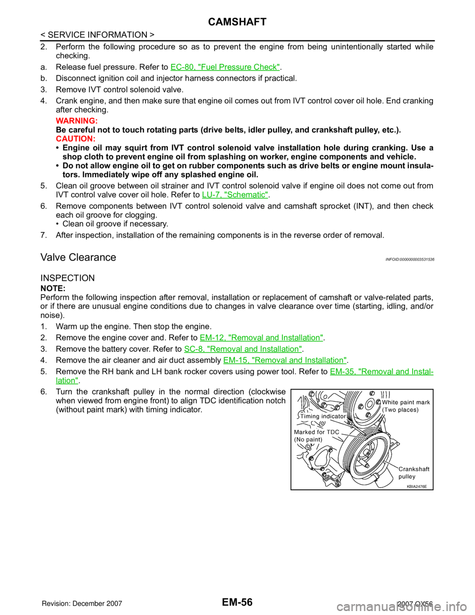
6. Turn the crankshaft pulley in the normal direction (clockwise when viewed from engine front) to align TDC identification notch
(without paint mark) with timing indicator.
KBIA2476E
Page 1994 of 3061

GI-28
< SERVICE INFORMATION >
SERVICE INFORMATION FOR ELECTRICAL INCIDENT
ough understanding of system operation. Then you will be able to use the appropriate equipment and follow
the correct test procedure.
You may have to simulate vehicle vibrations while testing electrical components. Gently shake the wiring har-
ness or electrical component to do this.
NOTE:
Refer to “How to Check Terminal” to probe or check terminal.
Testing for “Opens” in the Circuit
Before you begin to diagnose and test the system, you should rough sketch a schematic of the system. This
will help you to logically walk through the diagnosis process. Drawing the sketch will also reinforce your work-
ing knowledge of the system.
CONTINUITY CHECK METHOD
The continuity check is used to find an open in the circuit. The digital multimeter (DMM) set on the resistance
function will indicate an open circuit as over limit (no beep tone or no ohms symbol). Make sure to always start
with the DMM at the highest resistance level.
To help in understanding the diagnosis of open circuits, please refer to the previous schematic.
• Disconnect the battery negative cable.
• Start at one end of the circuit and work your way to the other end. (At the fuse block in this example)
• Connect one probe of the DMM to the fuse block terminal on the load side.
• Connect the other probe to the fuse block (power) side of SW1. Little or no resistance will indicate that por-
tion of the circuit has good continuity. If there were an open in the circuit, the DMM would indicate an over
limit or infinite resistance condition. (point A)
• Connect the probes between SW1 and the relay. Little or no resistance will indicate that portion of the circuit
has good continuity. If there were an open in the circuit, the DMM would indicate an over limit or infinite resis-
tance condition. (point B)
• Connect the probes between the relay and the solenoid. Little or no resistance will indicate that portion of the
circuit has good continuity. If there were an open in the circuit, the DMM would indicate an over limit or infi-
nite resistance condition. (point C)
Any circuit can be diagnosed using the approach in the previous example.
VOLTAGE CHECK METHOD
To help in understanding the diagnosis of open circuits please refer to the previous schematic.
In any powered circuit, an open can be found by methodically checking the system for the presence of voltage.
This is done by switching the DMM to the voltage function.
• Connect one probe of the DMM to a known good ground.
• Begin probing at one end of the circuit and work your way to the other end.
• With SW1 open, probe at SW1 to check for voltage.
voltage; open is further down the circuit than SW1.
no voltage; open is between fuse block and SW1 (point A).
• Close SW1 and probe at relay.
voltage; open is further down the circuit than the relay.
no voltage; open is between SW1 and relay (point B).
OPEN A circuit is open when there is no continuity through a section of the circuit.
SHORTThere are two types of shorts.
• SHORT CIRCUITWhen a circuit contacts another circuit and causes the normal resistance to
change.
• SHORT TO GROUND When a circuit contacts a ground source and grounds the circuit.
SGI846-A
Page 2027 of 3061

GW-8
< SERVICE INFORMATION >
SQUEAK AND RATTLE TROUBLE DIAGNOSIS
Most of these incidents can be repaired by adjusting, securing or insulating the item(s) or component(s) caus-
ing the noise.
SUNROOF/HEADLINER
Noises in the sunroof/headliner area can often be traced to one of the following:
1. Sunroof lid, rail, linkage or seals making a rattle or light knocking noise
2. Sun visor shaft shaking in the holder
3. Front or rear windshield touching headliner and squeaking
Again, pressing on the components to stop the noise while duplicating the conditions can isolate most of these
incidents. Repairs usually consist of insulating with felt cloth tape.
OVERHEAD CONSOLE (FRONT AND REAR)
Overhead console noises are often caused by the console panel clips not being engaged correctly. Most of
these incidents are repaired by pushing up on the console at the clip locations until the clips engage.
In addition look for:
1. Loose harness or harness connectors.
2. Front console map/reading lamp lense loose.
3. Loose screws at console attachment points.
SEATS
When isolating seat noise it's important to note the position the seat is in and the load placed on the seat when
the noise is present. These conditions should be duplicated when verifying and isolating the cause of the
noise.
Cause of seat noise include:
1. Headrest rods and holder
2. A squeak between the seat pad cushion and frame
3. The rear seatback lock and bracket
These noises can be isolated by moving or pressing on the suspected components while duplicating the con-
ditions under which the noise occurs. Most of these incidents can be repaired by repositioning the component
or applying urethane tape to the contact area.
UNDERHOOD
Some interior noise may be caused by components under the hood or on the engine wall. The noise is then
transmitted into the passenger compartment.
Causes of transmitted underhood noise include:
1. Any component mounted to the engine wall
2. Components that pass through the engine wall
3. Engine wall mounts and connectors
4. Loose radiator mounting pins
5. Hood bumpers out of adjustment
6. Hood striker out of adjustment
These noises can be difficult to isolate since they cannot be reached from the interior of the vehicle. The best
method is to secure, move or insulate one component at a time and test drive the vehicle. Also, engine RPM
or load can be changed to isolate the noise. Repairs can usually be made by moving, adjusting, securing, or
insulating the component causing the noise.
Page 2119 of 3061

SQUEAK AND RATTLE TROUBLE DIAGNOSIS
IP-7
< SERVICE INFORMATION >
C
D
E
F
G
H
J
K
L
MA
B
IP
N
O
P
Most of these incidents can be repaired by adjusting, securing or insulating the item(s) or component(s) caus-
ing the noise.
SUNROOF/HEADLINING
Noises in the sunroof/headlining area can often be traced to one of the following:
1. Sunroof lid, rail, linkage or seals making a rattle or light knocking noise
2. Sun visor shaft shaking in the holder
3. Front or rear windshield touching headliner and squeaking
Again, pressing on the components to stop the noise while duplicating the conditions can isolate most of these
incidents. Repairs usually consist of insulating with felt cloth tape.
OVERHEAD CONSOLE (FRONT AND REAR)
Overhead console noises are often caused by the console panel clips not being engaged correctly. Most of
these incidents are repaired by pushing up on the console at the clip locations until the clips engage.
In addition look for:
1. Loose harness or harness connectors.
2. Front console map/reading lamp lens loose.
3. Loose screws at console attachment points.
SEATS
When isolating seat noise it's important to note the position the seat is in and the load placed on the seat when
the noise is present. These conditions should be duplicated when verifying and isolating the cause of the
noise.
Cause of seat noise include:
1. Headrest rods and holder
2. A squeak between the seat pad cushion and frame
3. The rearseat back lock and bracket
These noises can be isolated by moving or pressing on the suspected components while duplicating the con-
ditions under which the noise occurs. Most of these incidents can be repaired by repositioning the component
or applying urethane tape to the contact area.
UNDERHOOD
Some interior noise may be caused by components under the hood or on the engine wall. The noise is then
transmitted into the passenger compartment.
Causes of transmitted underhood noise include:
1. Any component mounted to the engine wall
2. Components that pass through the engine wall
3. Engine wall mounts and connectors
4. Loose radiator mounting pins
5. Hood bumpers out of adjustment
6. Hood striker out of adjustment
These noises can be difficult to isolate since they cannot be reached from the interior of the vehicle. The best
method is to secure, move or insulate one component at a time and test drive the vehicle. Also, engine RPM
or load can be changed to isolate the noise. Repairs can usually be made by moving, adjusting, securing, or
insulating the component causing the noise.
Page 2238 of 3061

HEADLAMP (FOR CANADA) - DAYTIME LIGHT SYSTEM -
LT-31
< SERVICE INFORMATION >
C
D
E
F
G
H
I
J
L
MA
B
LT
N
O
P
3. Perform the Preliminary Check. Refer to LT-31, "Preliminary Check" .
4. Check symptom and repair or replace the cause of malfunction.
5. Does the headlamp operate normally? If YES: GO TO 6. If NO: GO TO 4.
6. Inspection End.
Preliminary CheckINFOID:0000000003533360
CHECK BCM CONFIGURATION
1.CHECK BCM CONFIGURATION
Confirm BCM configuration for "DTRL" is set to "WITH". Refer to BCS-18, "
Configuration" .
OK or NG
OK >> Continue preliminary check. Refer to BCS-15, "BCM Power Supply and Ground Circuit Inspec-
tion" .
NG >> Change BCM configuration for "DTRL" to "WITH". Refer to BCS-18, "
Configuration" .
INSPECT POWER SUPPLY AND GROUND CIRCUIT FOR BCM
Refer to BCS-15, "BCM Power Supply and Ground Circuit Inspection".
INSPECTION PARKING BRAKE SWITCH CIRCUIT
1.CHECK BRAKE INDICATOR
1. Turn ignition switch ON.
2. Apply parking brake.
3. Release parking brake.
OK or NG
OK >> Inspection End.
NG >> GO TO 2.
2.CHECK PARKING BRAKE SWITCH SIGNAL
1. Turn ignition switch OFF.
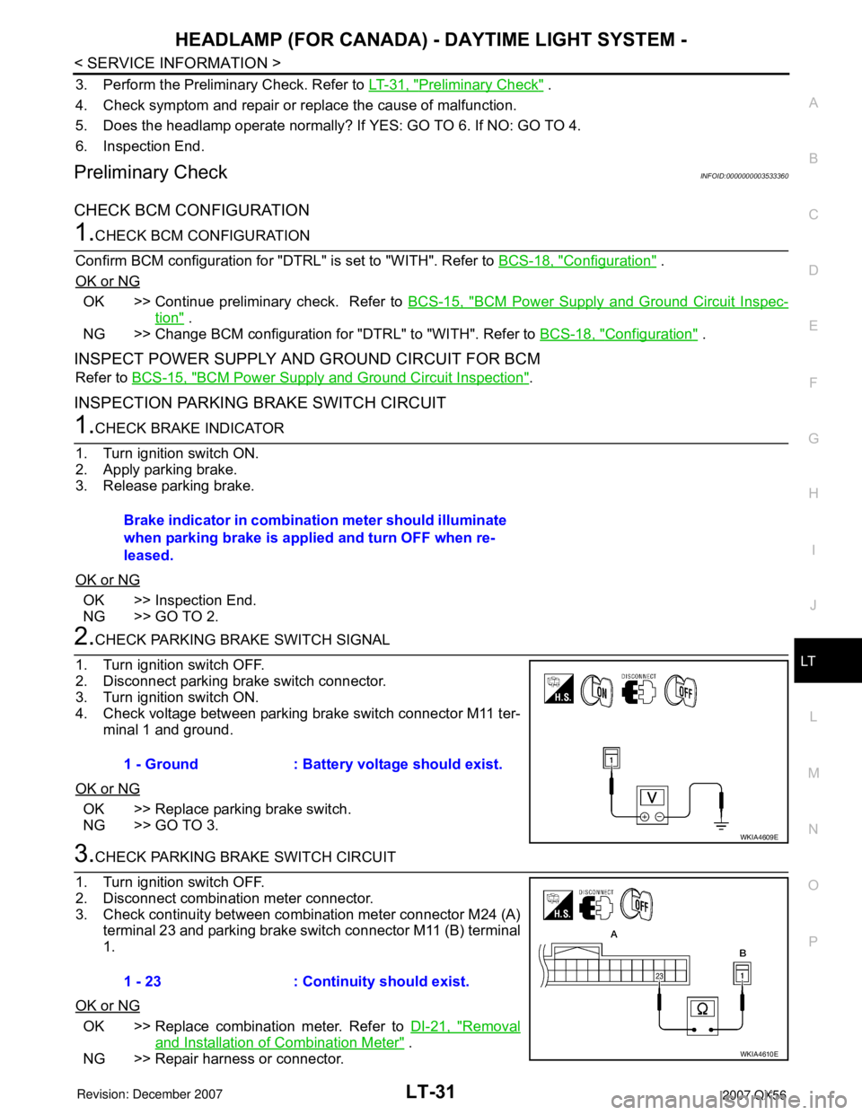
2. Disconnect parking brake switch connector.
3. Turn ignition switch ON.
4. Check voltage between parking brake switch connector M11 ter-
minal 1 and ground.
OK or NG
OK >> Replace parking brake switch.
NG >> GO TO 3.
3.CHECK PARKING BRAKE SWITCH CIRCUIT
1. Turn ignition switch OFF.
2. Disconnect combination meter connector.
3. Check continuity between combination meter connector M24 (A)
terminal 23 and parking brake switch connector M11 (B) terminal
1.
OK or NG
OK >> Replace combination meter. Refer to DI-21, "Removal
and Installation of Combination Meter" .
NG >> Repair harness or connector.Brake indicator in combination meter should illuminate
when parking brake is applied and turn OFF when re-
leased.
1 - Ground : Battery voltage should exist.
WKIA4609E
1 - 23 : Continuity should exist.
WKIA4610E