2007 INFINITI QX56 change time
[x] Cancel search: change timePage 2547 of 3061
SUNROOF
RF-15
< SERVICE INFORMATION >
C
D
E
F
G
H
J
K
L
MA
B
RF
N
O
P
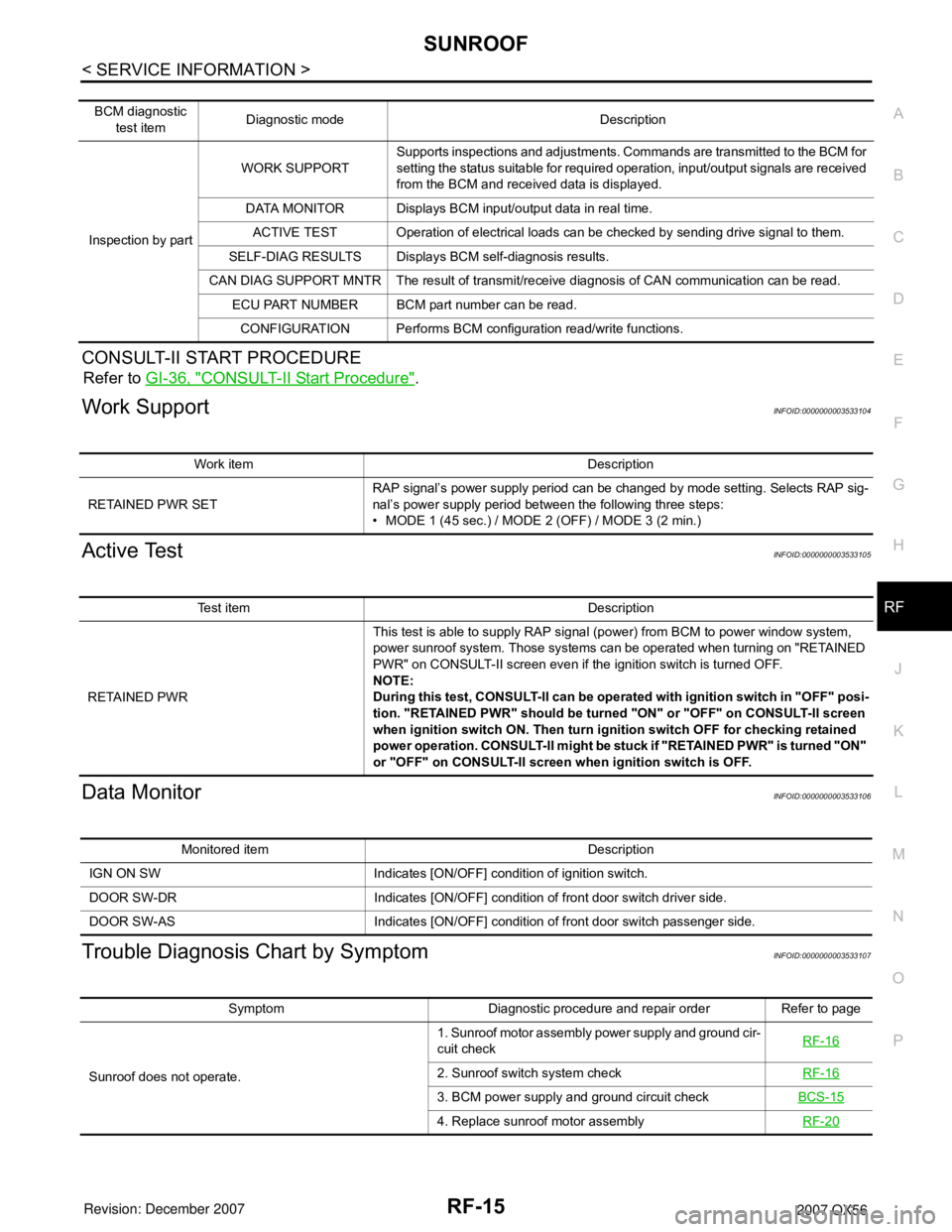
CONSULT-II START PROCEDURE
Refer to GI-36, "CONSULT-II Start Procedure".
Work SupportINFOID:0000000003533104
Active TestINFOID:0000000003533105
Data MonitorINFOID:0000000003533106
Trouble Diagnosis Chart by SymptomINFOID:0000000003533107
BCM diagnostic
test itemDiagnostic mode Description
Inspection by partWORK SUPPORTSupports inspections and adjustments. Commands are transmitted to the BCM for
setting the status suitable for required operation, input/output signals are received
from the BCM and received data is displayed.
DATA MONITOR Displays BCM input/output data in real time.
ACTIVE TEST Operation of electrical loads can be checked by sending drive signal to them.
SELF-DIAG RESULTS Displays BCM self-diagnosis results.
CAN DIAG SUPPORT MNTR The result of transmit/receive diagnosis of CAN communication can be read.
ECU PART NUMBER BCM part number can be read.
CONFIGURATION Performs BCM configuration read/write functions.
Work item Description
RETAINED PWR SETRAP signal’s power supply period can be changed by mode setting. Selects RAP sig-
nal’s power supply period between the following three steps:
• MODE 1 (45 sec.) / MODE 2 (OFF) / MODE 3 (2 min.)
Test item Description
RETAINED PWRThis test is able to supply RAP signal (power) from BCM to power window system,
power sunroof system. Those systems can be operated when turning on "RETAINED
PWR" on CONSULT-II screen even if the ignition switch is turned OFF.
NOTE:
During this test, CONSULT-II can be operated with ignition switch in "OFF" posi-
tion. "RETAINED PWR" should be turned "ON" or "OFF" on CONSULT-II screen
when ignition switch ON. Then turn ignition switch OFF for checking retained
power operation. CONSULT-II might be stuck if "RETAINED PWR" is turned "ON"
or "OFF" on CONSULT-II screen when ignition switch is OFF.
Monitored item Description
IGN ON SW Indicates [ON/OFF] condition of ignition switch.
DOOR SW-DR Indicates [ON/OFF] condition of front door switch driver side.
DOOR SW-AS Indicates [ON/OFF] condition of front door switch passenger side.
Symptom Diagnostic procedure and repair order Refer to page
Sunroof does not operate.1. Sunroof motor assembly power supply and ground cir-
cuit checkRF-16
2. Sunroof switch system checkRF-16
3. BCM power supply and ground circuit checkBCS-15
4. Replace sunroof motor assemblyRF-20
Page 2614 of 3061
RSU-24
< SERVICE INFORMATION >
REAR SUSPENSION ASSEMBLY
• Check with the manufacturer of your specific alignment machine for their recommended Service/Cali-
bration Schedule.
THE ALIGNMENT PROCESS
IMPORTANT: Use only the alignment specifications listed in this Service Manual. Refer to FSU-19, "Wheel
Alignment (Unladen*1) *6" .
1. When displaying the alignment settings, many alignment machines use “indicators”: (Green/red, plus or
minus, Go/No Go). Do NOT use these indicators.
• The alignment specifications programmed into your alignment machine that operate these indicators
may not be correct.
• This may result in an ERROR.
2. Some newer alignment machines are equipped with an optional “Rolling Compensation” method to “com-
pensate” the sensors (alignment targets or head units). Do NOT use this “Rolling Compensation”
method.
• Use the “Jacking Compensation” method. After installing the alignment targets or head units, raise the
vehicle and rotate the wheels 1/2 turn both ways.
• See Instructions in the alignment machine you are using for more information.
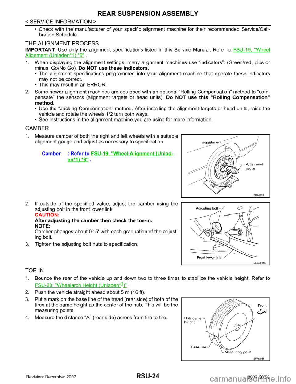
CAMBER
1. Measure camber of both the right and left wheels with a suitable
alignment gauge and adjust as necessary to specification.
2. If outside of the specified value, adjust the camber using the
adjusting bolt in the front lower link.
CAUTION:
After adjusting the camber then check the toe-in.
NOTE:
Camber changes about 0° 5' with each graduation of the adjust-
ing bolt.
3. Tighten the adjusting bolt nuts to specification.
TOE-IN
1. Bounce the rear of the vehicle up and down two to three times to stabilize the vehicle height. Refer to
FSU-20, "
Wheelarch Height (Unladen*1)" .
2. Push the vehicle straight ahead about 5 m (16 ft).
3. Put a mark on the base line of the tread (rear side) of both of the
tires at the same height as the center of the hub. This will be the
measuring points.
4. Measure the distance “A” (rear side) across from tire to tire.Camber : Refer to FSU-19, "
Wheel Alignment (Unlad-
en*1) *6" .
SRA096A
LEIA0041E
SFA614B
Page 2680 of 3061

SE-8
< SERVICE INFORMATION >
SQUEAK AND RATTLE TROUBLE DIAGNOSIS
Most of these incidents can be repaired by adjusting, securing or insulating the item(s) or component(s) caus-
ing the noise.
SUNROOF/HEADLINING
Noises in the sunroof/headlining area can often be traced to one of the following:
1. Sunroof lid, rail, linkage or seals making a rattle or light knocking noise
2. Sun visor shaft shaking in the holder
3. Front or rear windshield touching headliner and squeaking
Again, pressing on the components to stop the noise while duplicating the conditions can isolate most of these
incidents. Repairs usually consist of insulating with felt cloth tape.
OVERHEAD CONSOLE (FRONT AND REAR)
Overhead console noises are often caused by the console panel clips not being engaged correctly. Most of
these incidents are repaired by pushing up on the console at the clip locations until the clips engage.
In addition look for:
1. Loose harness or harness connectors.
2. Front console map/reading lamp lense loose.
3. Loose screws at console attachment points.
SEATS
When isolating seat noise it's important to note the position the seat is in and the load placed on the seat when
the noise is present. These conditions should be duplicated when verifying and isolating the cause of the
noise.
Cause of seat noise include:
1. Headrest rods and holder
2. A squeak between the seat pad cushion and frame
3. The rear seatback lock and bracket
These noises can be isolated by moving or pressing on the suspected components while duplicating the con-
ditions under which the noise occurs. Most of these incidents can be repaired by repositioning the component
or applying urethane tape to the contact area.
UNDERHOOD
Some interior noise may be caused by components under the hood or on the engine wall. The noise is then
transmitted into the passenger compartment.
Causes of transmitted underhood noise include:
1. Any component mounted to the engine wall
2. Components that pass through the engine wall
3. Engine wall mounts and connectors
4. Loose radiator mounting pins
5. Hood bumpers out of adjustment
6. Hood striker out of adjustment
These noises can be difficult to isolate since they cannot be reached from the interior of the vehicle. The best
method is to secure, move or insulate one component at a time and test drive the vehicle. Also, engine RPM
or load can be changed to isolate the noise. Repairs can usually be made by moving, adjusting, securing, or
insulating the component causing the noise.
Page 2788 of 3061
SRS-18
< SERVICE INFORMATION >
TROUBLE DIAGNOSIS
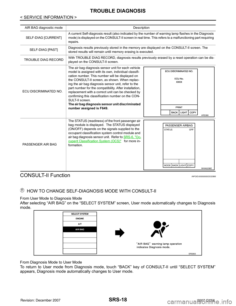
CONSULT-II Function
INFOID:0000000003532866
HOW TO CHANGE SELF-DIAGNOSIS MODE WITH CONSULT-II
From User Mode to Diagnosis Mode
After selecting “AIR BAG” on the “SELECT SYSTEM” screen, User mode automatically changes to Diagnosis
mode.
From Diagnosis Mode to User Mode
To return to User mode from Diagnosis mode, touch “BACK” key of CONSULT-II until “SELECT SYSTEM”
appears, Diagnosis mode automatically changes to User mode.
AIR BAG diagnostic mode Description
SELF-DIAG [CURRENT]A current Self-diagnosis result (also indicated by the number of warning lamp flashes in the Diagnosis
mode) is displayed on the CONSULT-II screen in real time. This refers to a malfunctioning part requiring
repairs.
SELF-DIAG [PAST]Diagnosis results previously stored in the memory are displayed on the CONSULT-II screen. The
stored results will remain until memory erasing is executed.
TROUBLE DIAG RECORDWith TROUBLE DIAG RECORD, diagnosis results previously erased by a reset operation can be dis-
played on the CONSULT-II screen.
ECU DISCRIMINATED NO.The air bag diagnosis sensor unit for each vehicle
model is assigned with its own, individual classifi-
cation number. This number will be displayed on
the CONSULT-II screen, as shown. When replac-
ing the air bag diagnosis sensor unit, refer to the
part number for the compatibility. After installation,
replacement with a correct unit can be checked by
confirming this classification number on the CON-
SULT-II screen.
The air bag diagnosis sensor unit discriminated
number assigned is F649.
PASSENGER AIR BAGThe STATUS (readiness) of the front passenger air
bag module is displayed. The STATUS displayed
(ON/OFF) depends on the signals supplied to the
occupant classification system control module and
air bag diagnosis sensor unit. Refer to SRS-6, "
Oc-
cupant Classification System (OCS)" for more in-
formation.
ARS366
WHIA0290E
SRS803
Page 2790 of 3061
SRS-20
< SERVICE INFORMATION >
TROUBLE DIAGNOSIS
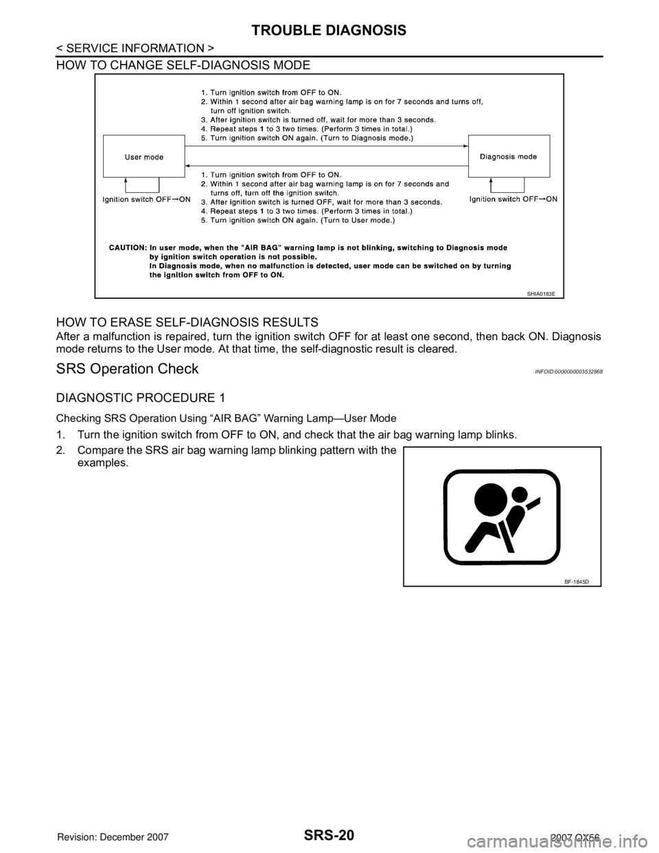
HOW TO CHANGE SELF-DIAGNOSIS MODE
HOW TO ERASE SELF-DIAGNOSIS RESULTS
After a malfunction is repaired, turn the ignition switch OFF for at least one second, then back ON. Diagnosis
mode returns to the User mode. At that time, the self-diagnostic result is cleared.
SRS Operation CheckINFOID:0000000003532868
DIAGNOSTIC PROCEDURE 1
Checking SRS Operation Using “AIR BAG” Warning Lamp—User Mode
1. Turn the ignition switch from OFF to ON, and check that the air bag warning lamp blinks.
2. Compare the SRS air bag warning lamp blinking pattern with the
examples.
SHIA0183E
BF-1845D
Page 2856 of 3061
TF-34
< SERVICE INFORMATION >
TROUBLE DIAGNOSIS
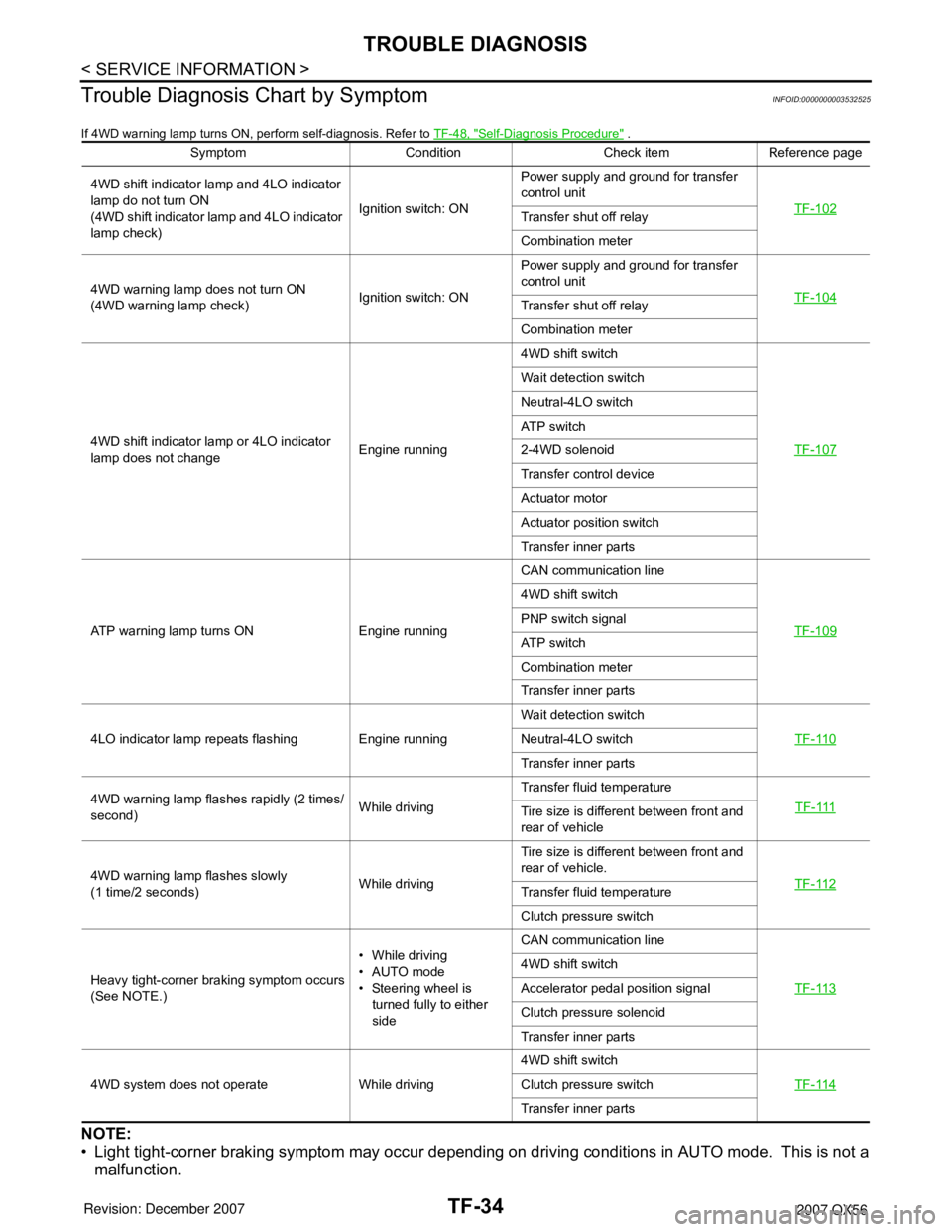
Trouble Diagnosis Chart by Symptom
INFOID:0000000003532525
If 4WD warning lamp turns ON, perform self-diagnosis. Refer to TF-48, "Self-Diagnosis Procedure" .
NOTE:
• Light tight-corner braking symptom may occur depending on driving conditions in AUTO mode. This is not a
malfunction.
Symptom Condition Check item Reference page
4WD shift indicator lamp and 4LO indicator
lamp do not turn ON
(4WD shift indicator lamp and 4LO indicator
lamp check)Ignition switch: ONPower supply and ground for transfer
control unit
TF-102
Transfer shut off relay
Combination meter
4WD warning lamp does not turn ON
(4WD warning lamp check)Ignition switch: ONPower supply and ground for transfer
control unit
TF-104
Transfer shut off relay
Combination meter
4WD shift indicator lamp or 4LO indicator
lamp does not changeEngine running4WD shift switch
TF-107
Wait detection switch
Neutral-4LO switch
ATP switch
2-4WD solenoid
Transfer control device
Actuator motor
Actuator position switch
Transfer inner parts
ATP warning lamp turns ON Engine runningCAN communication line
TF-109
4WD shift switch
PNP switch signal
ATP switch
Combination meter
Transfer inner parts
4LO indicator lamp repeats flashing Engine runningWait detection switch
TF-110
Neutral-4LO switch
Transfer inner parts
4WD warning lamp flashes rapidly (2 times/
second)While drivingTransfer fluid temperature
TF-111
Tire size is different between front and
rear of vehicle
4WD warning lamp flashes slowly
(1 time/2 seconds)While drivingTire size is different between front and
rear of vehicle.
TF-112
Transfer fluid temperature
Clutch pressure switch
Heavy tight-corner braking symptom occurs
(See NOTE.)• While driving
•AUTO mode
• Steering wheel is
turned fully to either
sideCAN communication line
TF-113
4WD shift switch
Accelerator pedal position signal
Clutch pressure solenoid
Transfer inner parts
4WD system does not operate While driving4WD shift switch
TF-114
Clutch pressure switch
Transfer inner parts
Page 2869 of 3061
TROUBLE DIAGNOSIS
TF-47
< SERVICE INFORMATION >
C
E
F
G
H
I
J
K
L
MA
B
TF
N
O
PWORK SUPPORT
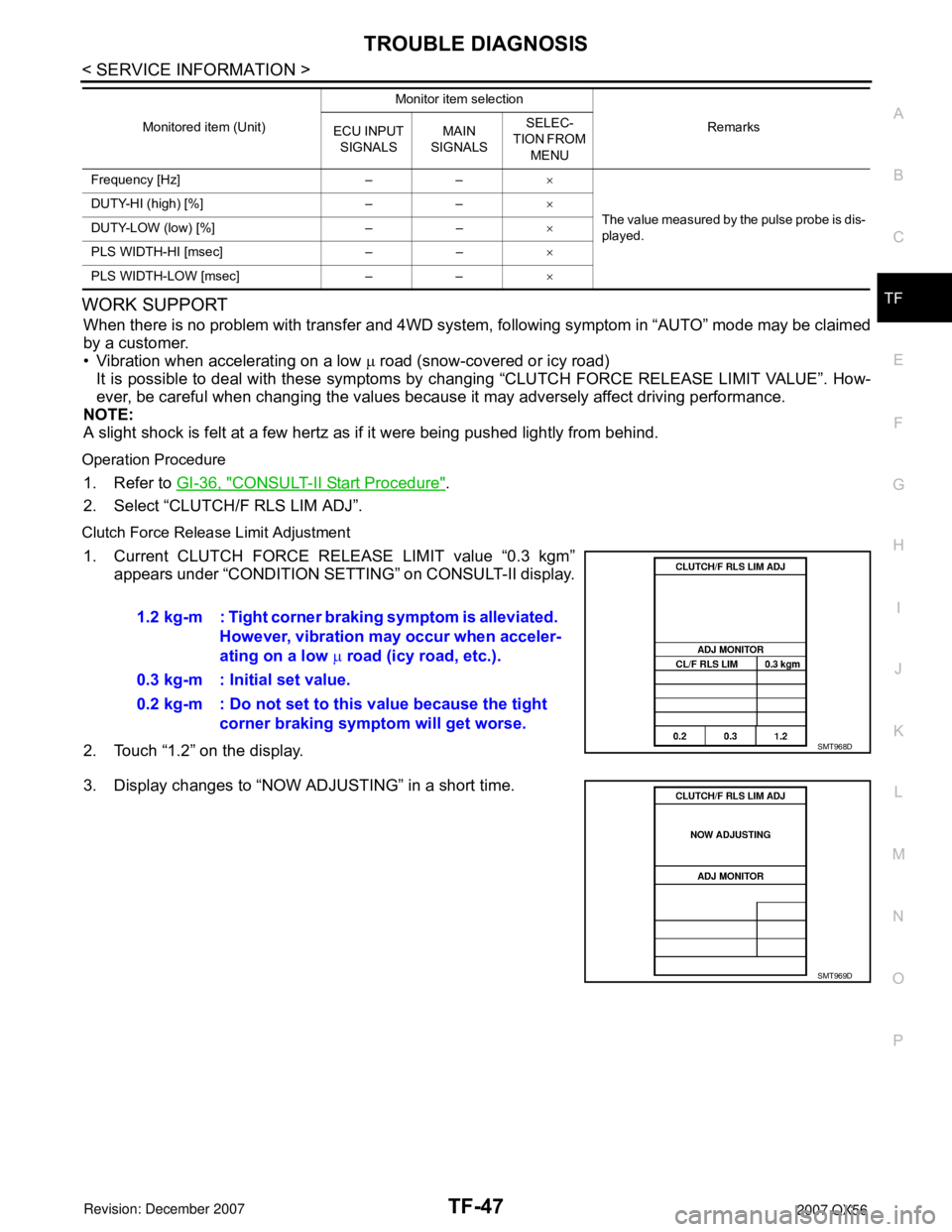
When there is no problem with transfer and 4WD system, following symptom in “AUTO” mode may be claimed
by a customer.
• Vibration when accelerating on a low µ road (snow-covered or icy road)
It is possible to deal with these symptoms by changing “CLUTCH FORCE RELEASE LIMIT VALUE”. How-
ever, be careful when changing the values because it may adversely affect driving performance.
NOTE:
A slight shock is felt at a few hertz as if it were being pushed lightly from behind.
Operation Procedure
1. Refer to GI-36, "CONSULT-II Start Procedure".
2. Select “CLUTCH/F RLS LIM ADJ”.
Clutch Force Release Limit Adjustment
1. Current CLUTCH FORCE RELEASE LIMIT value “0.3 kgm”
appears under “CONDITION SETTING” on CONSULT-II display.
2. Touch “1.2” on the display.
3. Display changes to “NOW ADJUSTING” in a short time.
Frequency [Hz] – –×
The value measured by the pulse probe is dis-
played. DUTY-HI (high) [%] – –×
DUTY-LOW (low) [%] – –×
PLS WIDTH-HI [msec] – –×
PLS WIDTH-LOW [msec] – –× Monitored item (Unit)Monitor item selection
Remarks
ECU INPUT
SIGNALSMAIN
SIGNALSSELEC-
TION FROM
MENU
1.2 kg-m : Tight corner braking symptom is alleviated.
However, vibration may occur when acceler-
ating on a low µ road (icy road, etc.).
0.3 kg-m : Initial set value.
0.2 kg-m : Do not set to this value because the tight
corner braking symptom will get worse.
SMT968D
SMT969D
Page 3028 of 3061
FRONT WIPER AND WASHER SYSTEM
WW-11
< SERVICE INFORMATION >
C
D
E
F
G
H
I
J
L
MA
B
WW
N
O
P
CONSULT-II Function (BCM)INFOID:0000000003533560
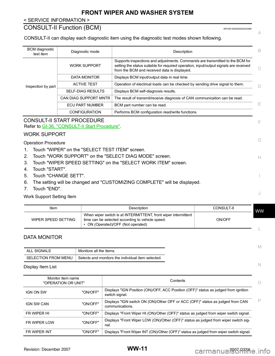
CONSULT-II can display each diagnostic item using the diagnostic test modes shown following.
CONSULT-II START PROCEDURE
Refer to GI-36, "CONSULT-II Start Procedure".
WORK SUPPORT
Operation Procedure
1. Touch "WIPER" on the "SELECT TEST ITEM" screen.
2. Touch "WORK SUPPORT" on the "SELECT DIAG MODE" screen.
3. Touch "WIPER SPEED SETTING" on the "SELECT WORK ITEM" screen.
4. Touch "START".
5. Touch "CHANGE SETT".
6. The setting will be changed and "CUSTOMIZING COMPLETE" will be displayed.
7. Touch "END".
Work Support Setting Item
DATA MONITOR
Display Item List
BCM diagnostic
test itemDiagnostic mode Description
Inspection by partWORK SUPPORTSupports inspections and adjustments. Commands are transmitted to the BCM for
setting the status suitable for required operation, input/output signals are received
from the BCM and received data is displayed.
DATA MONITOR Displays BCM input/output data in real time.
ACTIVE TEST Operation of electrical loads can be checked by sending drive signal to them.
SELF-DIAG RESULTS Displays BCM self-diagnosis results.
CAN DIAG SUPPORT MNTR The result of transmit/receive diagnosis of CAN communication can be read.
ECU PART NUMBER BCM part number can be read.
CONFIGURATION Performs BCM configuration read/write functions.
Item Description CONSULT-II
WIPER SPEED SETTINGWhen wiper switch is at INTERMITTENT, front wiper intermittent
time can be selected according to vehicle speed.
• ON (Operated)/OFF (Not operated)ON/OFF
ALL SIGNALS Monitors all the items.
SELECTION FROM MENU Selects and monitors the individual item selected.
Monitor item name
"OPERATION OR UNIT"Contents
IGN ON SW "ON/OFF"Displays "IGN Position (ON)/OFF, ACC Position (OFF)" status as judged from ignition
switch signal.
IGN SW CAN "ON/OFF"Displays "IGN switch ON (ON)/Other OFF or ACC (OFF)" status as judged from CAN
communications.
FR WIPER HI "ON/OFF" Displays "Front Wiper HI (ON)/Other (OFF)" status as judged from wiper switch signal.
FR WIPER LOW "ON/OFF"Displays "Front Wiper LOW (ON)/Other (OFF)" status as judged from wiper switch sig-
nal.
FR WIPER INT "ON/OFF" Displays "Front Wiper INT (ON)/Other (OFF)" status as judged from wiper switch signal.