2007 INFINITI QX56 brake light
[x] Cancel search: brake lightPage 1685 of 3061
EC-602
< SERVICE INFORMATION >
ASCD BRAKE SWITCH
>> Repair open circuit or short to ground or short to power in harness or connectors.
9.CHECK STOP LAMP SWITCH INPUT SIGNAL CIRCUIT FOR OPEN AND SHORT
1. Disconnect ECM harness connector.
2. Check harness continuity between ECM terminal 101 and stop lamp switch terminal 4.
Refer to Wiring Diagram.
3. Also check harness for short to ground and short to power.
OK or NG
OK >> GO TO 10.
NG >> Repair open circuit or short to ground or short to power in harness or connectors.
10.CHECK STOP LAMP SWITCH
Refer to EC-602, "
Component Inspection" .
OK or NG
OK >> GO TO 11.
NG >> Replace stop lamp switch.
11 .CHECK INTERMITTENT INCIDENT
Refer to EC-138
.
>>INSPECTION END
Component InspectionINFOID:0000000003532152
ASCD BRAKE SWITCH
1. Turn ignition switch OFF.
2. Disconnect ASCD brake switch harness connector.
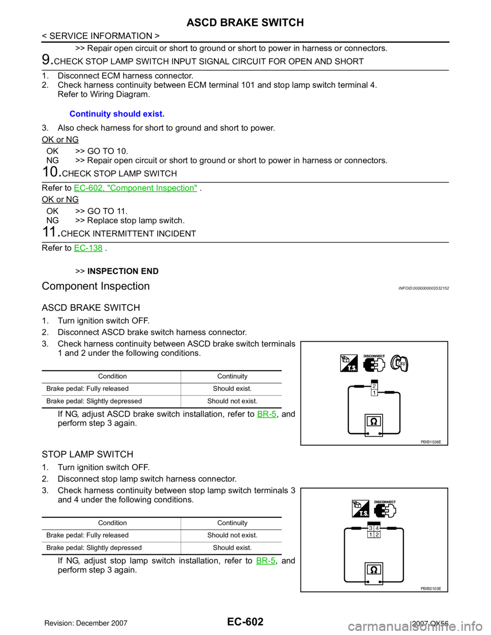
3. Check harness continuity between ASCD brake switch terminals
1 and 2 under the following conditions.
If NG, adjust ASCD brake switch installation, refer to BR-5
, and
perform step 3 again.
STOP LAMP SWITCH
1. Turn ignition switch OFF.
2. Disconnect stop lamp switch harness connector.
3. Check harness continuity between stop lamp switch terminals 3
and 4 under the following conditions.
If NG, adjust stop lamp switch installation, refer to BR-5
, and
perform step 3 again.Continuity should exist.
Condition Continuity
Brake pedal: Fully released Should exist.
Brake pedal: Slightly depressed Should not exist.
PBIB1536E
Condition Continuity
Brake pedal: Fully released Should not exist.
Brake pedal: Slightly depressed Should exist.
PBIB2103E
Page 1702 of 3061
ICC BRAKE SWITCH
EC-619
< SERVICE INFORMATION >
C
D
E
F
G
H
I
J
K
L
MA
EC
N
P O
ICC BRAKE SWITCH
Component DescriptionINFOID:0000000003532172
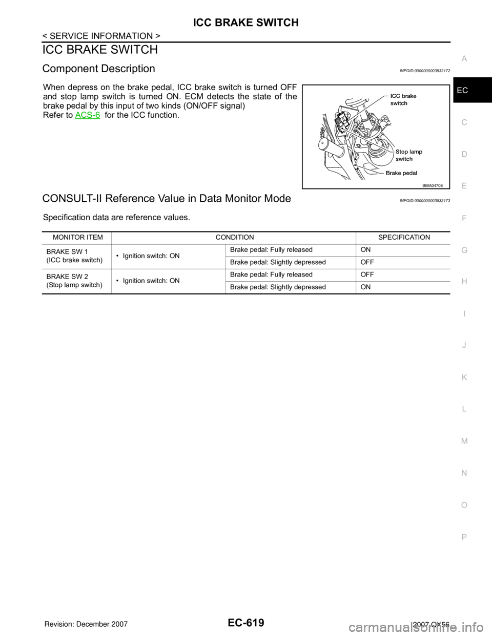
When depress on the brake pedal, ICC brake switch is turned OFF
and stop lamp switch is turned ON. ECM detects the state of the
brake pedal by this input of two kinds (ON/OFF signal)
Refer to ACS-6
for the ICC function.
CONSULT-II Reference Value in Data Monitor ModeINFOID:0000000003532173
Specification data are reference values.
BBIA0470E
MONITOR ITEM CONDITION SPECIFICATION
BRAKE SW 1
(ICC brake switch)• Ignition switch: ONBrake pedal: Fully released ON
Brake pedal: Slightly depressed OFF
BRAKE SW 2
(Stop lamp switch)• Ignition switch: ONBrake pedal: Fully released OFF
Brake pedal: Slightly depressed ON
Page 1704 of 3061
ICC BRAKE SWITCH
EC-621
< SERVICE INFORMATION >
C
D
E
F
G
H
I
J
K
L
MA
EC
N
P O
Diagnosis ProcedureINFOID:0000000003532175
1.CHECK OVERALL FUNCTION-I
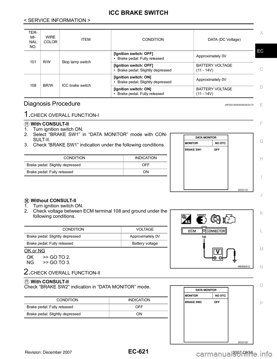
With CONSULT-II
1. Turn ignition switch ON.
2. Select “BRAKE SW1” in “DATA MONITOR” mode with CON-
SULT-II.
3. Check “BRAKE SW1” indication under the following conditions.
Without CONSULT-II
1. Turn ignition switch ON.
2. Check voltage between ECM terminal 108 and ground under the
following conditions.
OK or NG
OK >> GO TO 2.
NG >> GO TO 3.
2.CHECK OVERALL FUNCTION-II
With CONSULT-II
Check “BRAKE SW2” indication in “DATA MONITOR” mode.
TER-
MI-
NAL
NO.WIRE
COLORITEM CONDITION DATA (DC Voltage)
101 R/W Stop lamp switch[Ignition switch: OFF]
• Brake pedal: Fully releasedApproximately 0V
[Ignition switch: OFF]
• Brake pedal: Slightly depressedBATTERY VOLTAGE
(11 - 14V)
108 BR/W ICC brake switch[Ignition switch: ON]
• Brake pedal: Slightly depressedApproximately 0V
[Ignition switch: ON]
• Brake pedal: Fully releasedBATTERY VOLTAGE
(11 - 14V)
CONDITION INDICATION
Brake pedal: Slightly depressed OFF
Brake pedal: Fully released ON
SEC011D
CONDITION VOLTAGE
Brake pedal: Slightly depressed Approximately 0V
Brake pedal: Fully released Battery voltage
MBIB0061E
CONDITION INDICATION
Brake pedal: Fully released OFF
Brake pedal: Slightly depressed ON
SEC013D
Page 1705 of 3061
EC-622
< SERVICE INFORMATION >
ICC BRAKE SWITCH
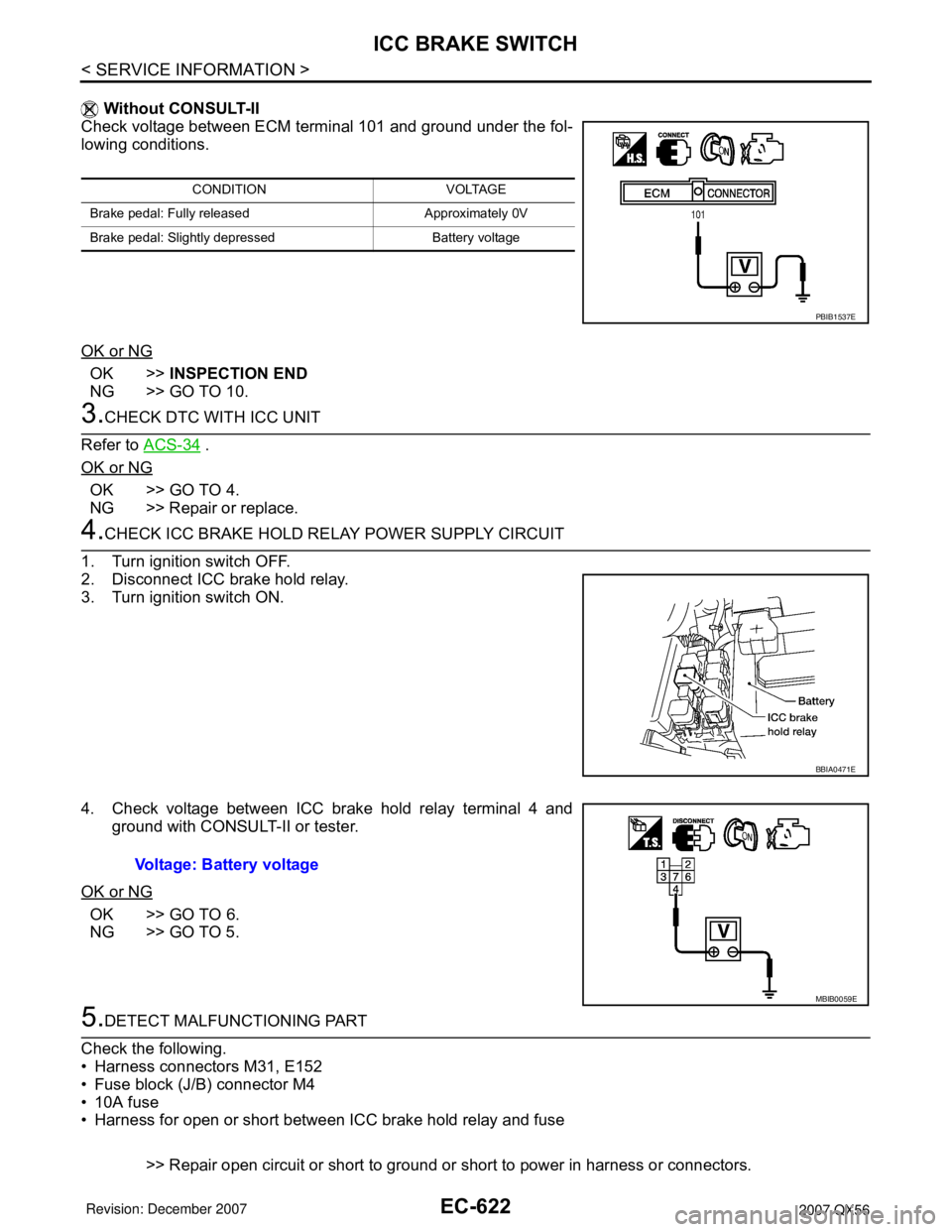
Without CONSULT-II
Check voltage between ECM terminal 101 and ground under the fol-
lowing conditions.
OK or NG
OK >>INSPECTION END
NG >> GO TO 10.
3.CHECK DTC WITH ICC UNIT
Refer to ACS-34
.
OK or NG
OK >> GO TO 4.
NG >> Repair or replace.
4.CHECK ICC BRAKE HOLD RELAY POWER SUPPLY CIRCUIT
1. Turn ignition switch OFF.
2. Disconnect ICC brake hold relay.
3. Turn ignition switch ON.
4. Check voltage between ICC brake hold relay terminal 4 and
ground with CONSULT-II or tester.
OK or NG
OK >> GO TO 6.
NG >> GO TO 5.
5.DETECT MALFUNCTIONING PART
Check the following.
• Harness connectors M31, E152
• Fuse block (J/B) connector M4
• 10A fuse
• Harness for open or short between ICC brake hold relay and fuse
>> Repair open circuit or short to ground or short to power in harness or connectors.
CONDITION VOLTAGE
Brake pedal: Fully released Approximately 0V
Brake pedal: Slightly depressed Battery voltage
PBIB1537E
BBIA0471E
Voltage: Battery voltage
MBIB0059E
Page 1708 of 3061
ICC BRAKE SWITCH
EC-625
< SERVICE INFORMATION >
C
D
E
F
G
H
I
J
K
L
MA
EC
N
P O
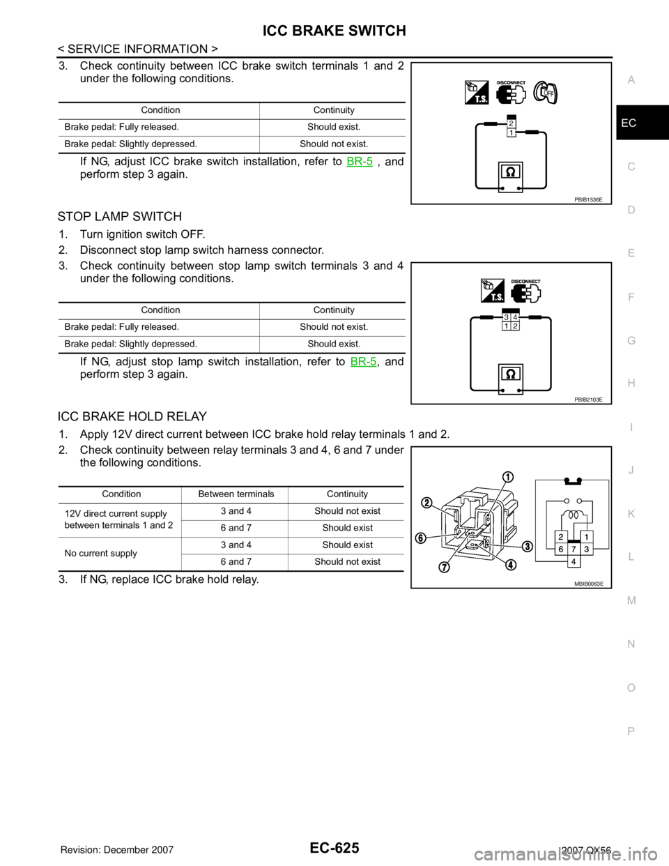
3. Check continuity between ICC brake switch terminals 1 and 2
under the following conditions.
If NG, adjust ICC brake switch installation, refer to BR-5
, and
perform step 3 again.
STOP LAMP SWITCH
1. Turn ignition switch OFF.
2. Disconnect stop lamp switch harness connector.
3. Check continuity between stop lamp switch terminals 3 and 4
under the following conditions.
If NG, adjust stop lamp switch installation, refer to BR-5
, and
perform step 3 again.
ICC BRAKE HOLD RELAY
1. Apply 12V direct current between ICC brake hold relay terminals 1 and 2.
2. Check continuity between relay terminals 3 and 4, 6 and 7 under
the following conditions.
3. If NG, replace ICC brake hold relay.
Condition Continuity
Brake pedal: Fully released. Should exist.
Brake pedal: Slightly depressed. Should not exist.
PBIB1536E
Condition Continuity
Brake pedal: Fully released. Should not exist.
Brake pedal: Slightly depressed. Should exist.
PBIB2103E
Condition Between terminals Continuity
12V direct current supply
between terminals 1 and 23 and 4 Should not exist
6 and 7 Should exist
No current supply3 and 4 Should exist
6 and 7 Should not exist
MBIB0063E
Page 2107 of 3061
IDX-3
A
C
D
E
F
G
H
I
J
K
L B
IDX
ALPHABETICAL INDEX
Brake fluid level ................................................. MA-28
Brake hydraulic line ........................................... BR-12
Brake inspection ................................................ MA-28
Brake lines and cables inspection ..................... MA-28
Brake master cylinder ....................................... BR-15
Brake switch ...................................... EC-572, EC-584
BRK/SW - Wiring diagram ............................... EC-585
Bulb specifications ........................................... LT-148
Bumper, front ...................................................... EI-13
Bumper, rear ....................................................... EI-15
C
Cabin air filter .................................................... MA-21
Camshaft ........................................................... EM-46
Camshaft inspection .......................................... EM-49
Camshaft position sensor (PHASE) ................ EC-369
CAN - Wiring diagram .............. EC-157, AT-93, AT-94
CAN communication EC-32, EC-156, EC-159, TF-112,
RSU-6
Canister-See EVAP canister ............................. EC-36
Center case (Transfer) ....................... TF-154, TF-167
CHARGE - Wiring diagram ............................... SC-19
Charging system ............................................... SC-17
Chassis and body maintenance ........................ MA-21
Chassis and body maintenanceSchedule 1 ........ MA-8
Chassis and body maintenanceSchedule 2 ...... MA-10
CHIME - Wiring diagram ..................................... DI-41
Circuit breaker ................................................... PG-17
Clock ................................................................... DI-61
CLOCK - Wiring diagram .................................... DI-61
Closed loop control ............................. EC-26, EC-501
Closed loop control (Bank 1) ........................... EC-501
Closed loop control (Bank 2) ........................... EC-501
Clutch drum (Transfer) ....................... TF-154, TF-167
Clutch pressure switch (Transfer) ...... TF-154, TF-167
Coil spring (front) ............................................. FSU-10
Collision diagnosis .......................................... SRS-53
Combination lamp, front, removal and installation . LT-
25
Combination lamp, rear, removal and installation .. LT-
101
Combination meter ................................................ DI-5
Combination switch ............................................ LT-79
COMBSW - Wiring diagram ............................... LT-79
COMM - Wiring diagram ................................... AV-94
COMPAS - Wiring diagram ................................. DI-24
Compass ............................................................. DI-23
Component Location (auto A/C) ...................... ATC-38
Compressor clutch removal and installation . ATC-180
Compressor mounting ................................... ATC-179
Compressor precaution ................................... ATC-11
Compressor special service tool ..................... ATC-14
Condenser ..................................................... ATC-184
Connecting rod .................................................. EM-96
Connecting rod bearing clearance .................... EM-96
Connecting rod bushing clearance .................... EM-96
Console box - See Instrument panel ................... IP-10
CONSULT for VDC ......................................... BRC-27
CONSULT general information ........................... GI-37
CONSULT-II for engine ................................... EC-118
Control units (terminal arrangement) ................. PG-71
Control valve (A/T) ............................................. AT-36
Control valve (Transfer) ...................... TF-154, TF-167
Converter housing installation ............ AT-240, AT-244
COOL/F - Wiring diagram ................................ EC-507
Coolant mixture ratio ......................................... MA-12
Coolant replacement ............................ CO-10, MA-13
Cooling circuit (engine) ........................................ CO-8
Cooling fan ........................................................ CO-17
Cooling fan control ........................................... EC-504
Cooling fan motor ............................................ EC-513
Cooling unit (A/C evaporator) ....... ATC-157, ATC-186
Corrosion protection ......................................... BL-157
Crankcase ventilation system - See Positive crankcase
ventilation .......................................................... EC-46
Crankshaft ......................................................... EM-79
Crankshaft position sensor (POS) ................... EC-362
Crash zone sensor .......................................... SRS-48
CUR/SE - Wiring diagram ... EC-522, EC-529, EC-536,
EC-543
Cylinder block .................................................... EM-78
Cylinder block boring ......................................... EM-99
D
D/LOCK - Wiring diagram ................................... BL-19
Data link connector for Consult ......... EC-120, EC-132
Daytime light system .......................................... LT-27
Daytime running light - See Daytime light system .. LT-
27
DEF - Wiring diagram ....................................... GW-74
Diagnosis sensor unit ...................................... SRS-51
Diagnostic trouble code (DTC) for OBD system . EC-9,
EC-54
Diagnostic trouble code (DTC) inspection priority chart
EC-91
Differential carrier assembly ............................ RFD-15
Differential gear oil replacement ........................ MA-26
Dimensions ......................................................... GI-51
Direct clutch solenoid valve ................ AT-143, AT-145
Display and amp.assembly .............................. ATC-59
Display Control Unit ........................................... AV-83
Display Unit ....................................................... AV-83
Dome light - See Interior lamp .......................... LT-110
Door glass .......................................... GW-62, GW-65
Door lock .......................................................... BL-121
Door mirror lamp ............................................... LT-110
Door trim .............................................................. EI-32
Door, front ........................................... BL-117, GW-62
Door, rear ........................................... BL-117, GW-65
Drive belt ........................................................... EM-13
Drive chain (Transfer) ......................... TF-149, TF-176
Drive pinion diff. inspection .............................. RFD-18
Drive shaft (rear) ................................................ RAX-7
Driver air bag ................................................... SRS-39
DTC work support ............................................ EC-128
DTRL - Wiring diagram ....................................... LT-31
Page 2231 of 3061
LT-24
< SERVICE INFORMATION >
HEADLAMP (FOR CANADA) - DAYTIME LIGHT SYSTEM -
HEADLAMP (FOR CANADA) - DAYTIME LIGHT SYSTEM -
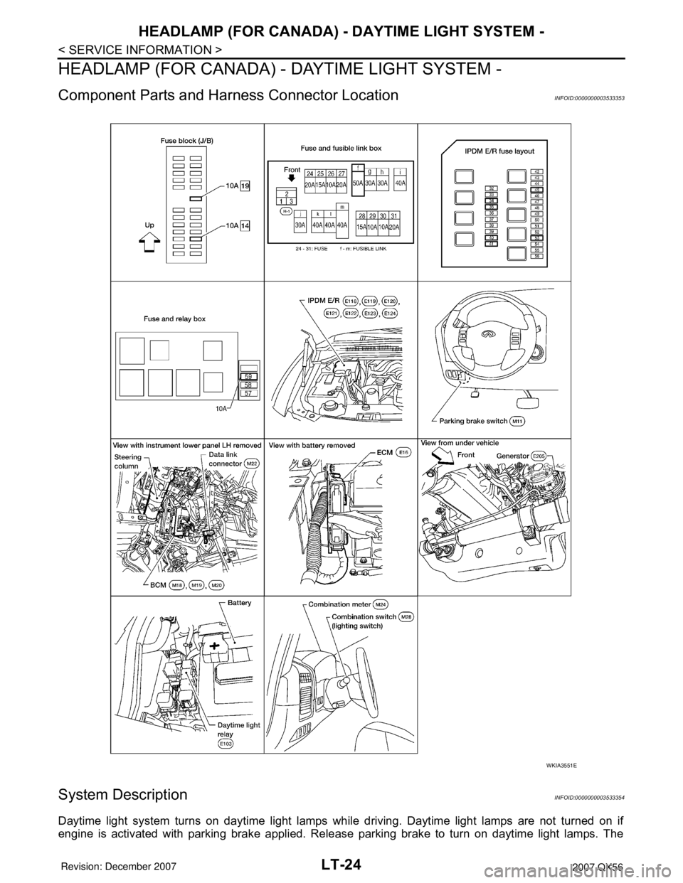
Component Parts and Harness Connector LocationINFOID:0000000003533353
System DescriptionINFOID:0000000003533354
Daytime light system turns on daytime light lamps while driving. Daytime light lamps are not turned on if
engine is activated with parking brake applied. Release parking brake to turn on daytime light lamps. The
WKIA3551E
Page 2232 of 3061
HEADLAMP (FOR CANADA) - DAYTIME LIGHT SYSTEM -
LT-25
< SERVICE INFORMATION >
C
D
E
F
G
H
I
J
L
MA
B
LT
N
O
P
lamps turn off when lighting switch is in the 2ND position or AUTO position (Headlamp is "ON") and when light-
ing switch is in the PASSING position. (Daytime light lamps are not turned off only by parking brake itself.)
A parking brake signal and engine run or stop signal are sent to BCM (body control module) by CAN commu-
nication line.
OUTLINE
Power is supplied at all times
• to ignition relay, located in the IPDM E/R (intelligent power distribution module engine room),
• through 50A fusible link (letter f , located in the fuse and fusible link box)
• to BCM terminal 70,
• through 20A fuse (No. 53, located in the IPDM E/R)
• to CPU (central processing unit) of the IPDM E/R,
• through 10A fuse [No. 19, located in the fuse block (J/B)]
• to combination meter terminal 8, and
• through 10A fuse (No. 45, located in the IPDM E/R)
• to daytime light relay terminals 2 and 5.
When the ignition switch is in ON or START position, power is supplied
• to ignition relay, located in the IPDM E/R,
• through 10A fuse (No. 59, located in the fuse and relay box)
• to BCM terminal 38, and
• through 10A fuse [No. 14, located in the fuse block (J/B)]
• to combination meter terminal 24.
Ground is supplied
• to BCM terminal 67 and
• to combination meter terminal 17
• through grounds M57, M61 and M79.
DAYTIME LIGHT OPERATION
With the engine running, the lighting switch in the OFF or 1ST position and parking brake released, the IPDM
E/R receives input requesting the daytime lights illuminate. This input is communicated across the CAN com-
munication lines. The CPU of the IPDM E/R controls the daytime light relay coil. When energized, this relay
directs power
• through daytime light relay terminal 3
• to front combination lamp LH terminal 2
• through front combination lamp LH terminal 6
• to IPDM E/R terminal 55
• through 10A fuse (No. 35, located in the IPDM E/R)
• through 10A fuse (No. 34, located in the IPDM E/R)
• through IPDM E/R terminal 56
• to front combination lamp RH terminal 6.
Ground is supplied
• to front combination lamp RH terminal 2
• through grounds E9, E15 and E24.
With power and ground supplied, the daytime lights illuminate. The high beam headlamps are now wired in
series and illuminate at a reduced intensity.
COMBINATION SWITCH READING FUNCTION
Refer to BCS-3, "System Description" .
AUTO LIGHT OPERATION
Refer to LT-34, "System Description" .
CAN Communication System DescriptionINFOID:0000000003533355
Refer to LAN-4, "CAN Communication System" .