2007 INFINITI QX56 MA-10
[x] Cancel search: MA-10Page 2392 of 3061
MA-30
< SERVICE INFORMATION >
CHASSIS AND BODY MAINTENANCE
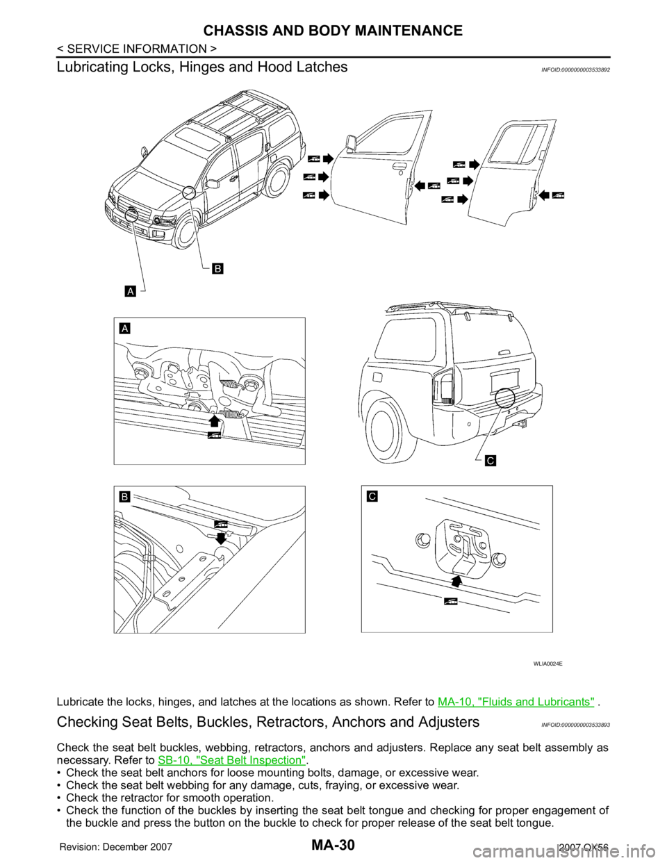
Lubricating Locks, Hinges and Hood Latches
INFOID:0000000003533892
Lubricate the locks, hinges, and latches at the locations as shown. Refer to MA-10, "Fluids and Lubricants" .
Checking Seat Belts, Buckles, Retractors, Anchors and AdjustersINFOID:0000000003533893
Check the seat belt buckles, webbing, retractors, anchors and adjusters. Replace any seat belt assembly as
necessary. Refer to SB-10, "
Seat Belt Inspection".
• Check the seat belt anchors for loose mounting bolts, damage, or excessive wear.
• Check the seat belt webbing for any damage, cuts, fraying, or excessive wear.
• Check the retractor for smooth operation.
• Check the function of the buckles by inserting the seat belt tongue and checking for proper engagement of
the buckle and press the button on the buckle to check for proper release of the seat belt tongue.
WLIA0024E
Page 2400 of 3061
PARKING BRAKE SHOE
PB-7
< SERVICE INFORMATION >
C
D
E
G
H
I
J
K
L
MA
B
PB
N
O
P
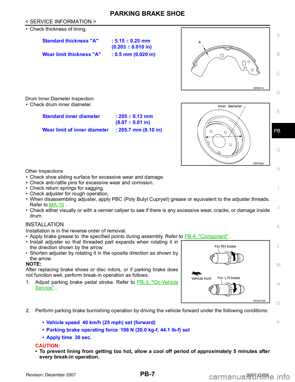
• Check thickness of lining.
Drum Inner Diameter Inspection
• Check drum inner diameter.
Other Inspections
• Check shoe sliding surface for excessive wear and damage.
• Check anti-rattle pins for excessive wear and corrosion.
• Check return springs for sagging.
• Check adjuster for rough operation.
• When disassembling adjuster, apply PBC (Poly Butyl Cuprysil) grease or equivalent to the adjuster threads.
Refer to MA-10
.
• Check either visually or with a vernier caliper to see if there is any excessive wear, cracks, or damage inside
drum.
INSTALLATION
Installation is in the reverse order of removal.
• Apply brake grease to the specified points during assembly. Refer to PB-4, "
Component" .
• Install adjuster so that threaded part expands when rotating it in
the direction shown by the arrow.
• Shorten adjuster by rotating it in the oposite direction as shown by
the arrow.
NOTE:
After replacing brake shoes or disc rotors, or if parking brake does
not function well, perform break-in operation as follows.
1. Adjust parking brake pedal stroke. Refer to PB-3, "
On-Vehicle
Service" .
2. Perform parking brake burnishing operation by driving the vehicle forward under the following conditions:
CAUTION:
• To prevent lining from getting too hot, allow a cool off period of approximately 5 minutes after
every break-in operation.Standard thickness "A" : 5.15 ± 0.25 mm
(0.203 ± 0.010 in)
Wear limit thickness "A" : 0.5 mm (0.020 in)
SBR021A
Standard inner diameter : 205 ± 0.13 mm
(8.07 ± 0.01 in)
Wear limit of inner diameter : 205.7 mm (8.10 in)
SBR768A
SFIA0153E
• Vehicle speed 40 km/h (25 mph) set (forward)
• Parking brake operating force 196 N (20.0 kg-f, 44.1 lb-f) set
• Apply time 30 sec.
Page 2497 of 3061
PS-6
< SERVICE INFORMATION >
POWER STEERING FLUID
POWER STEERING FLUID
Checking Fluid LevelINFOID:0000000003532821
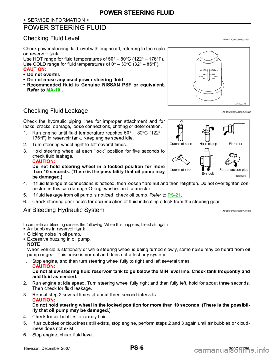
Check power steering fluid level with engine off, referring to the scale
on reservoir tank.
Use HOT range for fluid temperatures of 50° – 80°C (122° – 176°F).
Use COLD range for fluid temperatures of 0° – 30°C (32° – 86°F).
CAUTION:
• Do not overfill.
• Do not reuse any used power steering fluid.
• Recommended fluid is Genuine NISSAN PSF or equivalent.
Refer to MA-10
.
Checking Fluid LeakageINFOID:0000000003532822
Check the hydraulic piping lines for improper attachment and for
leaks, cracks, damage, loose connections, chafing or deterioration.
1. Run engine until fluid temperature reaches 50° – 80°C (122° –
176°F) in reservoir tank. Keep engine speed idle.
2. Turn steering wheel right-to-left several times.
3. Hold steering wheel at each “lock” position for five seconds to
check fluid leakage.
CAUTION:
Do not hold steering wheel in a locked position for more
than 10 seconds. (There is the possibility that oil pump may
be damaged.)
4. If fluid leakage at connections is noticed, then loosen flare nut and then retighten. Do not over tighten con-
nector as this can damage O-ring, washer and connector.
5. If fluid leakage from oil pump is noticed, check oil pump. Refer to PS-21
.
6. Check steering gear boots for accumulation of fluid indicating a leak from the steering gear.
Air Bleeding Hydraulic SystemINFOID:0000000003532823
Incomplete air bleeding causes the following. When this happens, bleed air again.
• Air bubbles in reservoir tank.
• Clicking noise in oil pump.
• Excessive buzzing in oil pump.
NOTE:
When vehicle is stationary or while steering wheel is being turned slowly, some noise may be heard from oil
pump or gear. This noise is normal and does not affect any system.
1. Stop engine, and then turn steering wheel fully to right and left several times.
CAUTION:
Do not allow steering fluid reservoir tank to go below the MIN level line. Check tank frequently and
add fluid as needed.
2. Run engine at idle speed. Turn steering wheel fully right and then fully left, hold for about three seconds.
Then check for fluid leakage.
3. Repeat step 2 several times at about three second intervals.
CAUTION:
Do not hold steering wheel in the locked position for more than 10 seconds. (There is the possibil-
ity that oil pump may be damaged.)
4. Check for air bubbles or cloudy fluid.
5. If air bubbles or cloudiness still exists, stop engine, perform steps 2 and 3 again until air bubbles or cloud-
iness does not exist.
6. Stop engine, check fluid level.
LGIA0021E
SGIA0506E
Page 2529 of 3061
REAR DRIVE SHAFT
RAX-11
< SERVICE INFORMATION >
C
E
F
G
H
I
J
K
L
MA
B
RAX
N
O
P
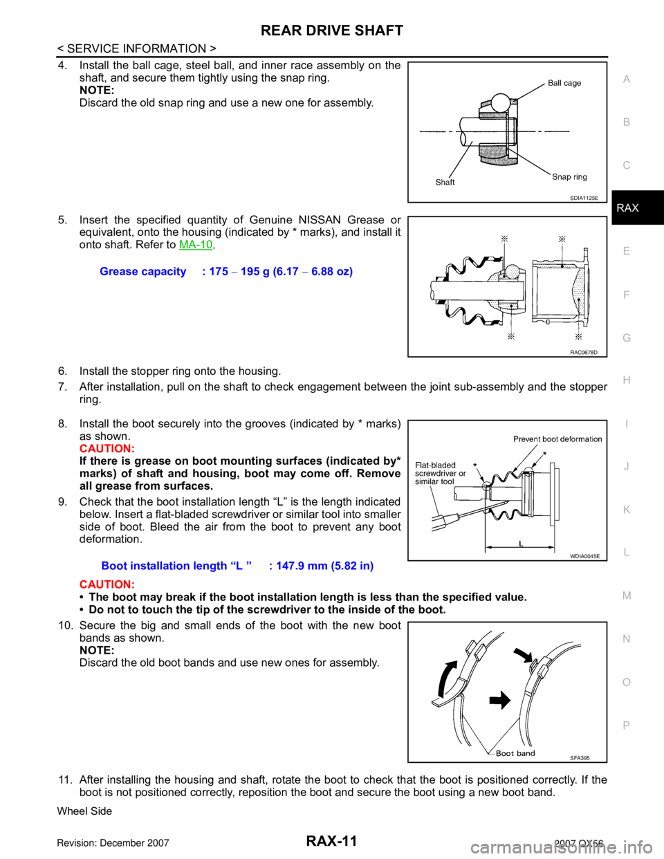
4. Install the ball cage, steel ball, and inner race assembly on the
shaft, and secure them tightly using the snap ring.
NOTE:
Discard the old snap ring and use a new one for assembly.
5. Insert the specified quantity of Genuine NISSAN Grease or
equivalent, onto the housing (indicated by * marks), and install it
onto shaft. Refer to MA-10
.
6. Install the stopper ring onto the housing.
7. After installation, pull on the shaft to check engagement between the joint sub-assembly and the stopper
ring.
8. Install the boot securely into the grooves (indicated by * marks)
as shown.
CAUTION:
If there is grease on boot mounting surfaces (indicated by*
marks) of shaft and housing, boot may come off. Remove
all grease from surfaces.
9. Check that the boot installation length “L” is the length indicated
below. Insert a flat-bladed screwdriver or similar tool into smaller
side of boot. Bleed the air from the boot to prevent any boot
deformation.
CAUTION:
• The boot may break if the boot installation length is less than the specified value.
• Do not to touch the tip of the screwdriver to the inside of the boot.
10. Secure the big and small ends of the boot with the new boot
bands as shown.
NOTE:
Discard the old boot bands and use new ones for assembly.
11. After installing the housing and shaft, rotate the boot to check that the boot is positioned correctly. If the
boot is not positioned correctly, reposition the boot and secure the boot using a new boot band.
Wheel Side
SDIA1125E
Grease capacity : 175 − 195 g (6.17 − 6.88 oz)
RAC0678D
Boot installation length “L ” : 147.9 mm (5.82 in)
WDIA0045E
SFA395
Page 2530 of 3061
RAX-12
< SERVICE INFORMATION >
REAR DRIVE SHAFT
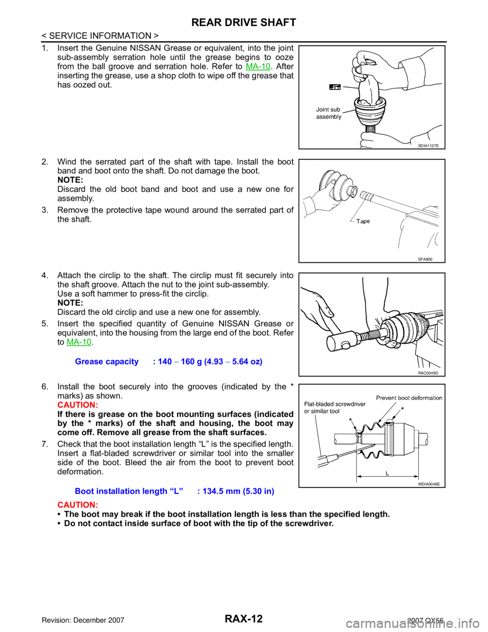
1. Insert the Genuine NISSAN Grease or equivalent, into the joint
sub-assembly serration hole until the grease begins to ooze
from the ball groove and serration hole. Refer to MA-10
. After
inserting the grease, use a shop cloth to wipe off the grease that
has oozed out.
2. Wind the serrated part of the shaft with tape. Install the boot
band and boot onto the shaft. Do not damage the boot.
NOTE:
Discard the old boot band and boot and use a new one for
assembly.
3. Remove the protective tape wound around the serrated part of
the shaft.
4. Attach the circlip to the shaft. The circlip must fit securely into
the shaft groove. Attach the nut to the joint sub-assembly.
Use a soft hammer to press-fit the circlip.
NOTE:
Discard the old circlip and use a new one for assembly.
5. Insert the specified quantity of Genuine NISSAN Grease or
equivalent, into the housing from the large end of the boot. Refer
to MA-10
.
6. Install the boot securely into the grooves (indicated by the *
marks) as shown.
CAUTION:
If there is grease on the boot mounting surfaces (indicated
by the * marks) of the shaft and housing, the boot may
come off. Remove all grease from the shaft surfaces.
7. Check that the boot installation length “L” is the specified length.
Insert a flat-bladed screwdriver or similar tool into the smaller
side of the boot. Bleed the air from the boot to prevent boot
deformation.
CAUTION:
• The boot may break if the boot installation length is less than the specified length.
• Do not contact inside surface of boot with the tip of the screwdriver.
SDIA1127E
SFA800
Grease capacity : 140 − 160 g (4.93 − 5.64 oz)
RAC0049D
Boot installation length “L” : 134.5 mm (5.30 in)
WDIA0046E
Page 2565 of 3061
RFD-8
< SERVICE INFORMATION >
DIFFERENTIAL GEAR OIL
DIFFERENTIAL GEAR OIL
Changing Differential Gear OilINFOID:0000000003532601
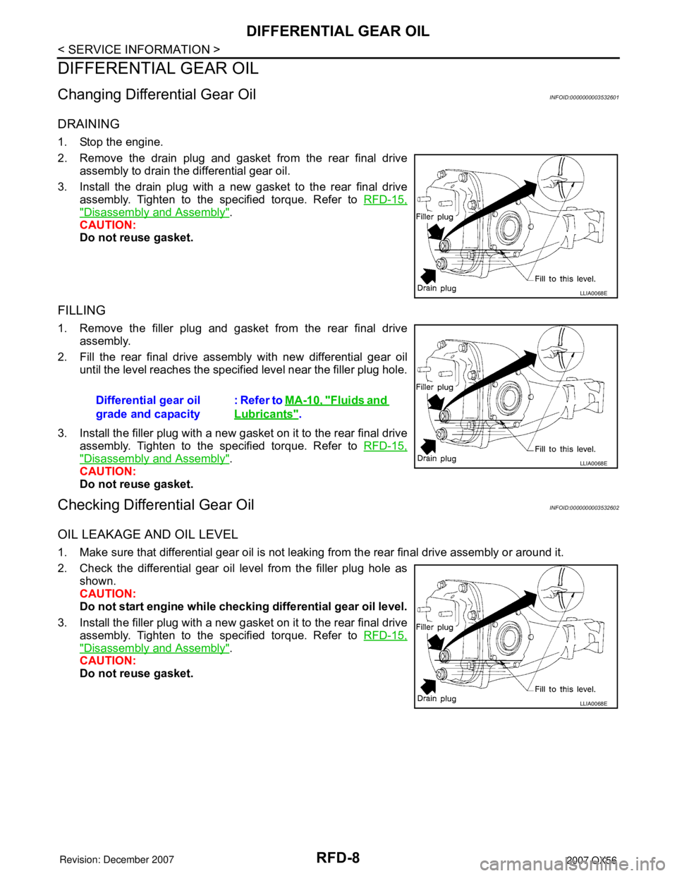
DRAINING
1. Stop the engine.
2. Remove the drain plug and gasket from the rear final drive
assembly to drain the differential gear oil.
3. Install the drain plug with a new gasket to the rear final drive
assembly. Tighten to the specified torque. Refer to RFD-15,
"Disassembly and Assembly".
CAUTION:
Do not reuse gasket.
FILLING
1. Remove the filler plug and gasket from the rear final drive
assembly.
2. Fill the rear final drive assembly with new differential gear oil
until the level reaches the specified level near the filler plug hole.
3. Install the filler plug with a new gasket on it to the rear final drive
assembly. Tighten to the specified torque. Refer to RFD-15,
"Disassembly and Assembly".
CAUTION:
Do not reuse gasket.
Checking Differential Gear OilINFOID:0000000003532602
OIL LEAKAGE AND OIL LEVEL
1. Make sure that differential gear oil is not leaking from the rear final drive assembly or around it.
2. Check the differential gear oil level from the filler plug hole as
shown.
CAUTION:
Do not start engine while checking differential gear oil level.
3. Install the filler plug with a new gasket on it to the rear final drive
assembly. Tighten to the specified torque. Refer to RFD-15,
"Disassembly and Assembly".
CAUTION:
Do not reuse gasket.
LLIA0068E
Differential gear oil
grade and capacity: Refer to MA-10, "Fluids and
Lubricants".
LLIA0068E
LLIA0068E
Page 2833 of 3061
TRANSFER FLUID
TF-11
< SERVICE INFORMATION >
C
E
F
G
H
I
J
K
L
MA
B
TF
N
O
P
TRANSFER FLUID
ReplacementINFOID:0000000003532513
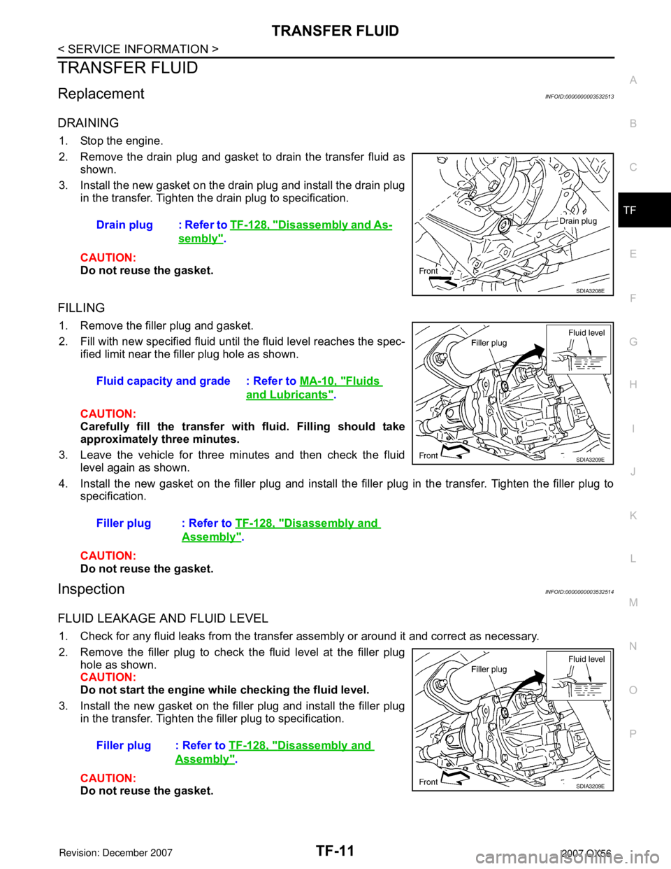
DRAINING
1. Stop the engine.
2. Remove the drain plug and gasket to drain the transfer fluid as
shown.
3. Install the new gasket on the drain plug and install the drain plug
in the transfer. Tighten the drain plug to specification.
CAUTION:
Do not reuse the gasket.
FILLING
1. Remove the filler plug and gasket.
2. Fill with new specified fluid until the fluid level reaches the spec-
ified limit near the filler plug hole as shown.
CAUTION:
Carefully fill the transfer with fluid. Filling should take
approximately three minutes.
3. Leave the vehicle for three minutes and then check the fluid
level again as shown.
4. Install the new gasket on the filler plug and install the filler plug in the transfer. Tighten the filler plug to
specification.
CAUTION:
Do not reuse the gasket.
InspectionINFOID:0000000003532514
FLUID LEAKAGE AND FLUID LEVEL
1. Check for any fluid leaks from the transfer assembly or around it and correct as necessary.
2. Remove the filler plug to check the fluid level at the filler plug
hole as shown.
CAUTION:
Do not start the engine while checking the fluid level.
3. Install the new gasket on the filler plug and install the filler plug
in the transfer. Tighten the filler plug to specification.
CAUTION:
Do not reuse the gasket.Drain plug : Refer to TF-128, "
Disassembly and As-
sembly".
SDIA3208E
Fluid capacity and grade : Refer to MA-10, "Fluids
and Lubricants".
Filler plug : Refer to TF-128, "
Disassembly and
Assembly".
SDIA3209E
Filler plug : Refer to TF-128, "Disassembly and
Assembly".
SDIA3209E