2007 INFINITI QX56 warning light
[x] Cancel search: warning lightPage 2178 of 3061
![INFINITI QX56 2007 Factory Service Manual TROUBLE DIAGNOSIS
LAN-47
< SERVICE INFORMATION >[CAN]
C
D
E
F
G
H
I
J
L
MA
B
LAN
N
O
P
Cooling fan speed request signal TR
Engine coolant temperature signal T R R
Engine speed signal T R R R R R R R
E INFINITI QX56 2007 Factory Service Manual TROUBLE DIAGNOSIS
LAN-47
< SERVICE INFORMATION >[CAN]
C
D
E
F
G
H
I
J
L
MA
B
LAN
N
O
P
Cooling fan speed request signal TR
Engine coolant temperature signal T R R
Engine speed signal T R R R R R R R
E](/manual-img/42/57029/w960_57029-2177.png)
TROUBLE DIAGNOSIS
LAN-47
< SERVICE INFORMATION >[CAN]
C
D
E
F
G
H
I
J
L
MA
B
LAN
N
O
P
Cooling fan speed request signal TR
Engine coolant temperature signal T R R
Engine speed signal T R R R R R R R
Engine status signal T R
Fuel consumption monitor signalTR
RT
ICC steering switch signal T R
Malfunction indicator lamp signal T R
Wide open throttle position signal T R
A/T CHECK indicator lamp signal T R
A/T fluid temperature sensor signal T R
A/T position indicator lamp signal T R R R
A/T self-diagnosis signal R T
Current gear position signal T R R
Output shaft revolution signal R T R R
P range signal T R R R R
Turbine revolution signal R T R
ICC sensor signal T R
Buzzer output signalTR
TR
ICC OD cancel request signal R R T
ICC operation signal R R T
ICC system display signal T R
System setting signalTR
RT
A/C switch signal R T R
Blower fan motor switch signal R T
Day time running light request signal T R R
Door switch signal R T R R R
Front fog light request signal T R
Front wiper request signal R T R
High beam request signal T R R
Horn chirp signal T R
Ignition switch signal R T R
Key fob door unlock signal R T
Key fob ID signal R T
Key switch signal R T
Low beam request signal T R
Position light request signal T R R
Rear window defogger switch signal T R R
Sleep wake up signal R T R R
Theft warning horn request signal T R
Tire pressure data signal T RSignal name/Connecting unit
ECM
TCM
LASER
ICC
ADP
BCM
DISP
HVAC
M&A
STRG
4WD
ABS
IPDM-E
Page 2209 of 3061

LT-2
Wiring Diagram - F/FOG - ......................................51
Terminal and Reference Value for BCM .................52
Terminal and Reference Value for IPDM E/R .........52
How to Proceed with Trouble Diagnosis .................53
Preliminary Check ..................................................53
CONSULT-II Function for BCM ..............................53
CONSULT-II Function for IPDM E/R ......................53
Front Fog Lamps Do Not Illuminate (Both Sides) ...53
Front Fog Lamp Does Not Illuminate (One Side) ...54
Aiming Adjustment ..................................................55
Bulb Replacement ..................................................55
Removal and Installation ........................................56
TURN SIGNAL AND HAZARD WARNING
LAMPS ...............................................................
57
Component Parts and Harness Connector Loca-
tion ..........................................................................
57
System Description .................................................57
CAN Communication System Description ..............59
Schematic ...............................................................60
Wiring Diagram - TURN - ........................................61
Terminal and Reference Value for BCM .................63
How to Proceed with Trouble Diagnosis .................63
Preliminary Check ..................................................64
CONSULT-II Function (BCM) .................................64
Front Turn Signal Lamp Does Not Operate ............64
Door Mirror Turn Signal Lamp Does Not Operate ...65
Rear Turn Signal Lamp Does Not Operate ............66
Hazard Warning Lamp Does Not Operate But
Turn Signal Lamp Operatess ..................................
67
Turn Signal Indicator Lamp Does Not Operate ......68
Bulb Replacement ..................................................69
Removal and Installation ........................................69
LIGHTING AND TURN SIGNAL SWITCH .........70
Removal and Installation ........................................70
HAZARD SWITCH .............................................71
Removal and Installation ........................................71
COMBINATION SWITCH ..................................72
Wiring Diagram - COMBSW - .................................72
Combination Switch Reading Function ...................72
CONSULT-II Function (BCM) .................................73
Combination Switch Inspection ..............................73
Removal and Installation ........................................76
Switch Circuit Inspection ........................................76
STOP LAMP ......................................................77
System Description .................................................77
Wiring Diagram - STOP/L - .....................................78
Bulb Replacement ..................................................78
Removal and Installation ........................................79
BACK-UP LAMP ................................................80
Wiring Diagram - BACK/L - .....................................80
Bulb Replacement ..................................................80
Removal and Installation ........................................81
PARKING, LICENSE PLATE AND TAIL
LAMPS ...............................................................
82
Component Parts and Harness Connector Loca-
tion ..........................................................................
82
System Description .................................................82
CAN Communication System Description ..............83
Schematic ...............................................................84
Wiring Diagram - TAIL/L - .......................................85
Terminal and Reference Value for BCM .................87
Terminal and Reference Value for IPDM E/R .........87
How to Proceed with Trouble Diagnosis .................88
Preliminary Check ...................................................88
CONSULT-II Function for BCM ...............................88
CONSULT-II Function for IPDM E/R .......................88
Parking, License Plate and/or Tail Lamps Do Not
Illuminate .................................................................
88
Parking, License Plate and Tail Lamps Do Not
Turn OFF (After Approx. 10 Minutes) .....................
91
Bulb Replacement ...................................................91
Removal and Installation .........................................92
REAR COMBINATION LAMP ...........................93
Bulb Replacement ...................................................93
Removal and Installation .........................................93
TRAILER TOW ..................................................94
Component Parts and Harness Connector Loca-
tion ..........................................................................
94
System Description .................................................94
Schematic ...............................................................96
Wiring Diagram - T/TOW - ......................................97
INTERIOR ROOM LAMP ..................................101
Component Parts and Harness Connector Loca-
tion ........................................................................
101
System Description ...............................................101
Schematic .............................................................105
Wiring Diagram - INT/L - .......................................107
Terminal and Reference Value for BCM ...............113
How to Proceed with Trouble Diagnosis ...............113
Preliminary Check .................................................114
CONSULT-II Function (BCM) ...............................114
Room/Map Lamp Control Does Not Operate ........115
Personal Lamp Control Does Not Operate (Room/
Map Lamps Operate) ............................................
116
All Step/Foot/Puddle Lamps Do Not Operate .......117
All Interior Room Lamps Do Not Operate .............118
Ignition Keyhole Illumination Control Does Not
Operate .................................................................
118
ILLUMINATION ................................................120
Component Parts and Harness Connector Loca-
tion ........................................................................
120
System Description ...............................................120
CAN Communication System Description ............122
Schematic .............................................................123
Wiring Diagram - ILL - ...........................................126
Removal and Installation of Illumination Control
Switch ...................................................................
136
Page 2211 of 3061

LT-4
< SERVICE INFORMATION >
PRECAUTIONS
SERVICE INFORMATION
PRECAUTIONS
Precaution for Supplemental Restraint System (SRS) "AIR BAG" and "SEAT BELT
PRE-TENSIONER"
INFOID:0000000003533330
The Supplemental Restraint System such as “AIR BAG” and “SEAT BELT PRE-TENSIONER”, used along
with a front seat belt, helps to reduce the risk or severity of injury to the driver and front passenger for certain
types of collision. This system includes seat belt switch inputs and dual stage front air bag modules. The SRS
system uses the seat belt switches to determine the front air bag deployment, and may only deploy one front
air bag, depending on the severity of a collision and whether the front occupants are belted or unbelted.
Information necessary to service the system safely is included in the SRS and SB section of this Service Man-
ual.
WARNING:
• To avoid rendering the SRS inoperative, which could increase the risk of personal injury or death in
the event of a collision which would result in air bag inflation, all maintenance must be performed by
an authorized NISSAN/INFINITI dealer.
• Improper maintenance, including incorrect removal and installation of the SRS, can lead to personal
injury caused by unintentional activation of the system. For removal of Spiral Cable and Air Bag
Module, see the SRS section.
• Do not use electrical test equipment on any circuit related to the SRS unless instructed to in this
Service Manual. SRS wiring harnesses can be identified by yellow and/or orange harnesses or har-
ness connectors.
General precautions for service operationsINFOID:0000000003533331
• Never work with wet hands.
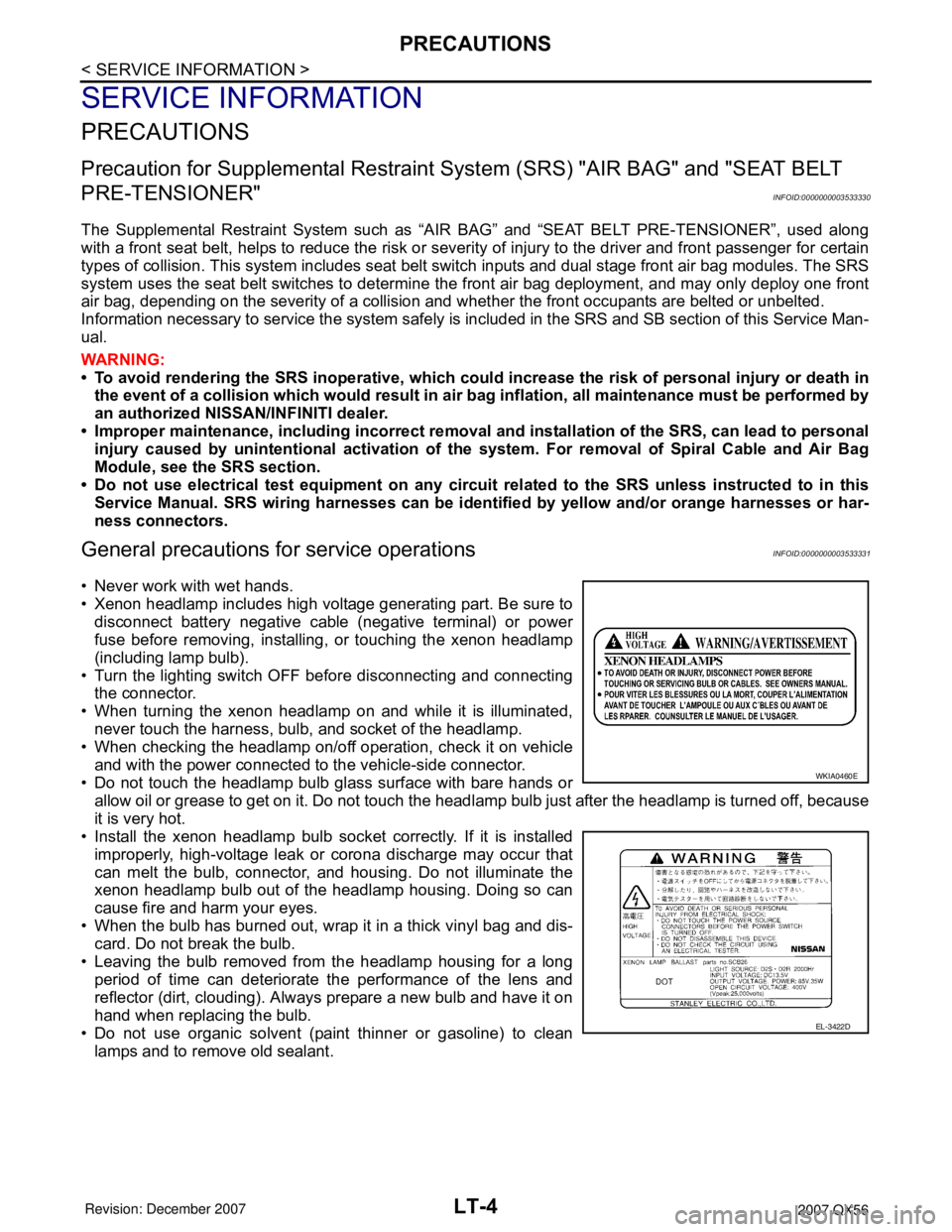
• Xenon headlamp includes high voltage generating part. Be sure to
disconnect battery negative cable (negative terminal) or power
fuse before removing, installing, or touching the xenon headlamp
(including lamp bulb).
• Turn the lighting switch OFF before disconnecting and connecting
the connector.
• When turning the xenon headlamp on and while it is illuminated,
never touch the harness, bulb, and socket of the headlamp.
• When checking the headlamp on/off operation, check it on vehicle
and with the power connected to the vehicle-side connector.
• Do not touch the headlamp bulb glass surface with bare hands or
allow oil or grease to get on it. Do not touch the headlamp bulb just after the headlamp is turned off, because
it is very hot.
• Install the xenon headlamp bulb socket correctly. If it is installed
improperly, high-voltage leak or corona discharge may occur that
can melt the bulb, connector, and housing. Do not illuminate the
xenon headlamp bulb out of the headlamp housing. Doing so can
cause fire and harm your eyes.
• When the bulb has burned out, wrap it in a thick vinyl bag and dis-
card. Do not break the bulb.
• Leaving the bulb removed from the headlamp housing for a long
period of time can deteriorate the performance of the lens and
reflector (dirt, clouding). Always prepare a new bulb and have it on
hand when replacing the bulb.
• Do not use organic solvent (paint thinner or gasoline) to clean
lamps and to remove old sealant.
WKIA0460E
EL-3422D
Page 2271 of 3061

LT-64
< SERVICE INFORMATION >
TURN SIGNAL AND HAZARD WARNING LAMPS
3. Perform preliminary check. Refer to LT-64, "Preliminary Check" .
4. Check symptom and repair or replace the component.
5. Do turn signal and hazard warning lamps operate normally? If YES: GO TO 6. If NO: GO TO 4.
6. Inspection End.
Preliminary CheckINFOID:0000000003533410
CHECK POWER SUPPLY AND GROUND CIRCUIT FOR BCM
Refer to BCS-15, "BCM Power Supply and Ground Circuit Inspection".
CONSULT-II Function (BCM)INFOID:0000000003533411
Refer to BCS-16, "CONSULT-II Function (BCM)".
CONSULT-II START PROCEDURE
Refer to GI-36, "CONSULT-II Start Procedure".
DATA MONITOR
Display Item List
ACTIVE TEST
Display Item List
Front Turn Signal Lamp Does Not OperateINFOID:0000000003533412
1.CHECK COMBINATION SWITCH INPUT SIGNAL
With CONSULT-II
Select "BCM" on CONSULT-II. With "FLASHER" data monitor, make
sure "TURN SIGNAL R" and "TURN SIGNAL L" turns ON-OFF
linked with operation of lighting switch.
Without CONSULT-II
Refer to LT-73, "
Combination Switch Inspection" .
OK or NG
OK >> GO TO 2.
NG >> Check lighting switch. Refer to LT-73, "
Combination Switch Inspection".
2.ACTIVE TEST
With CONSULT-II
Monitor item Contents
IGN ON SW "ON/OFF" Displays "IGN position (ON)/OFF, ACC position (OFF)" judged from the ignition switch signal.
HAZARD SW "ON/OFF" Displays "Hazard ON (ON)/Hazard OFF (OFF)" status, determined from hazard switch signal.
TURN SIGNAL R "ON/OFF" Displays "Turn right (ON)/Other (OFF)" status, determined from lighting switch signal.
TURN SIGNAL L "ON/OFF" Displays "Turn left (ON)/Other (OFF)" status, determined from lighting switch signal.
BRAKE SW "ON/OFF" Displays status of stop lamp switch.
Test item Description
FLASHER (RH) Turn signal lamp (right) can be operated by any ON-OFF operations.
FLASHER (LH) Turn signal lamp (left) can be operated by any ON-OFF operations.
When lighting switch is in
TURN RH position: TURN SIGNAL R ON
When lighting switch is in
TURN LH position: TURN SIGNAL L ON
SKIA4499E
Page 2273 of 3061

LT-66
< SERVICE INFORMATION >
TURN SIGNAL AND HAZARD WARNING LAMPS
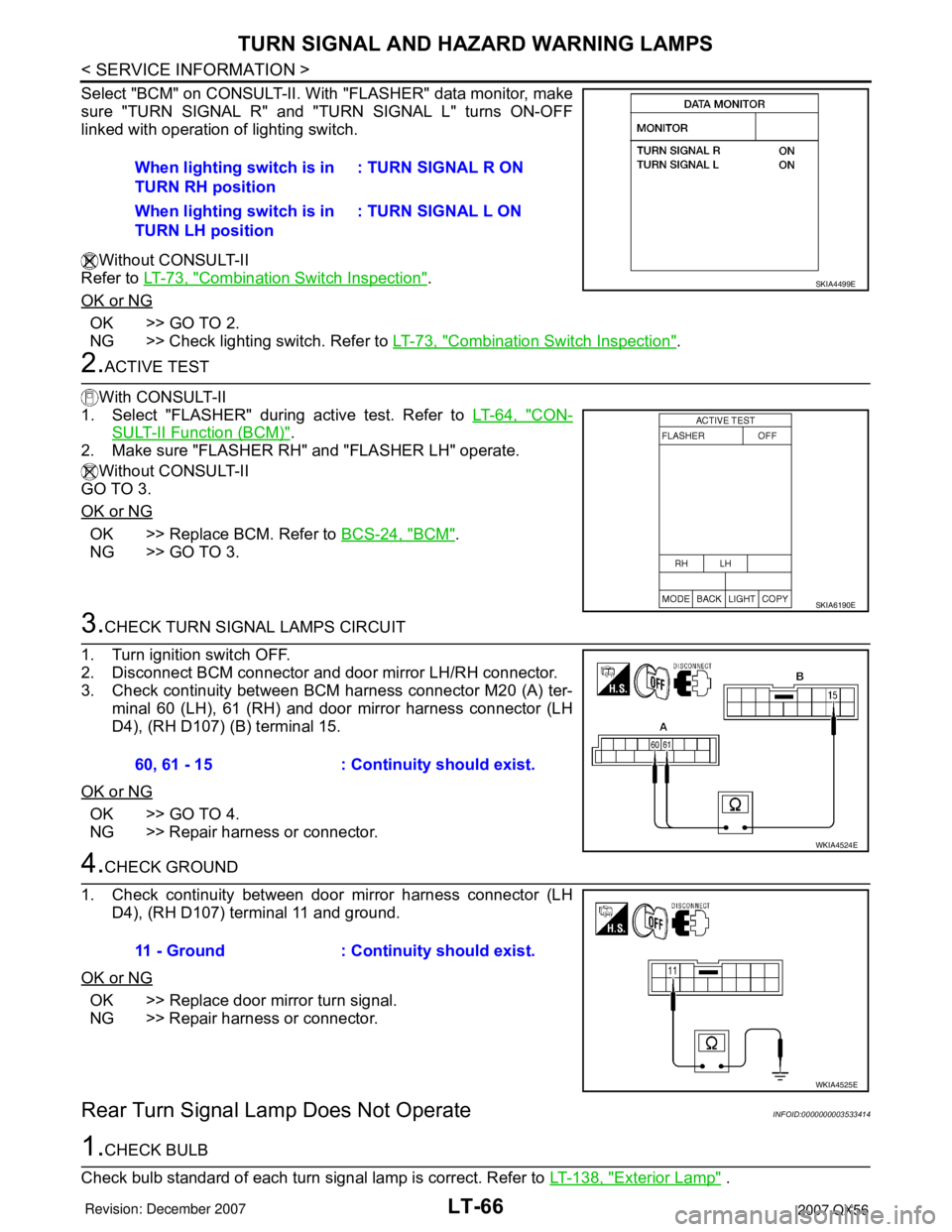
Select "BCM" on CONSULT-II. With "FLASHER" data monitor, make
sure "TURN SIGNAL R" and "TURN SIGNAL L" turns ON-OFF
linked with operation of lighting switch.
Without CONSULT-II
Refer to LT-73, "
Combination Switch Inspection".
OK or NG
OK >> GO TO 2.
NG >> Check lighting switch. Refer to LT-73, "
Combination Switch Inspection".
2.ACTIVE TEST
With CONSULT-II
1. Select "FLASHER" during active test. Refer to LT-64, "
CON-
SULT-II Function (BCM)".
2. Make sure "FLASHER RH" and "FLASHER LH" operate.
Without CONSULT-II
GO TO 3.
OK or NG
OK >> Replace BCM. Refer to BCS-24, "BCM".
NG >> GO TO 3.
3.CHECK TURN SIGNAL LAMPS CIRCUIT
1. Turn ignition switch OFF.
2. Disconnect BCM connector and door mirror LH/RH connector.
3. Check continuity between BCM harness connector M20 (A) ter-
minal 60 (LH), 61 (RH) and door mirror harness connector (LH
D4), (RH D107) (B) terminal 15.
OK or NG
OK >> GO TO 4.
NG >> Repair harness or connector.
4.CHECK GROUND
1. Check continuity between door mirror harness connector (LH
D4), (RH D107) terminal 11 and ground.
OK or NG
OK >> Replace door mirror turn signal.
NG >> Repair harness or connector.
Rear Turn Signal Lamp Does Not OperateINFOID:0000000003533414
1.CHECK BULB
Check bulb standard of each turn signal lamp is correct. Refer to LT-138, "
Exterior Lamp" . When lighting switch is in
TURN RH position: TURN SIGNAL R ON
When lighting switch is in
TURN LH position: TURN SIGNAL L ON
SKIA4499E
SKIA6190E
60, 61 - 15 : Continuity should exist.
WKIA4524E
11 - Ground : Continuity should exist.
WKIA4525E
Page 2347 of 3061

LU-2
< SERVICE INFORMATION >
PRECAUTIONS
SERVICE INFORMATION
PRECAUTIONS
Precaution for Supplemental Restraint System (SRS) "AIR BAG" and "SEAT BELT
PRE-TENSIONER"
INFOID:0000000003531549
The Supplemental Restraint System such as “AIR BAG” and “SEAT BELT PRE-TENSIONER”, used along
with a front seat belt, helps to reduce the risk or severity of injury to the driver and front passenger for certain
types of collision. Information necessary to service the system safely is included in the SRS and SB section of
this Service Manual.
WARNING:
• To avoid rendering the SRS inoperative, which could increase the risk of personal injury or death in
the event of a collision which would result in air bag inflation, all maintenance must be performed by
an authorized NISSAN/INFINITI dealer.
• Improper maintenance, including incorrect removal and installation of the SRS, can lead to personal
injury caused by unintentional activation of the system. For removal of Spiral Cable and Air Bag
Module, see the SRS section.
• Do not use electrical test equipment on any circuit related to the SRS unless instructed to in this
Service Manual. SRS wiring harnesses can be identified by yellow and/or orange harnesses or har-
ness connectors.
Precaution for Liquid GasketINFOID:0000000003531550
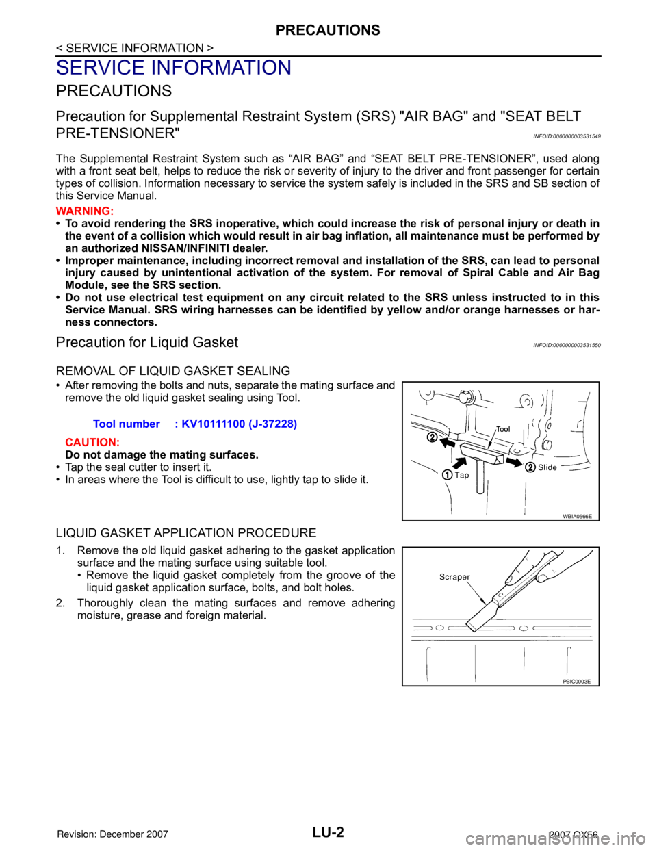
REMOVAL OF LIQUID GASKET SEALING
• After removing the bolts and nuts, separate the mating surface and
remove the old liquid gasket sealing using Tool.
CAUTION:
Do not damage the mating surfaces.
• Tap the seal cutter to insert it.
• In areas where the Tool is difficult to use, lightly tap to slide it.
LIQUID GASKET APPLICATION PROCEDURE
1. Remove the old liquid gasket adhering to the gasket application
surface and the mating surface using suitable tool.
• Remove the liquid gasket completely from the groove of the
liquid gasket application surface, bolts, and bolt holes.
2. Thoroughly clean the mating surfaces and remove adhering
moisture, grease and foreign material.Tool number : KV10111100 (J-37228)
WBIA0566E
PBIC0003E
Page 2462 of 3061

PG-60
< SERVICE INFORMATION >
HARNESS
Code Section Wiring Diagram Name
A/C,A ATC Auto Air Conditioner
A/SUSP RSU Rear Air Suspension
AF1B1 EC Air Fuel Ratio (A/F) Sensor 1 (Bank 1)
AF1B2 EC Air Fuel Ratio (A/F) Sensor 1 (Bank 2)
AF1HB1 EC Air Fuel Ratio (A/F) Sensor 1 (Bank 1)
AF1HB2 EC Air Fuel Ratio (A/F) Sensor 1 (Bank 2)
APPS1 EC Accelerator Pedal Position Sensor
APPS2 EC Accelerator Pedal Position Sensor
APPS3 EC Accelerator Pedal Position Sensor
ASC/BS EC ASCD Brake Switch
ASC/SW EC ASCD Steering Switch
ASCBOF EC ASCD Brake Switch
ASCIND EC ASCD Indicator
A/T AT A/T Assembly
AT/IND DI A/T Indicator Lamp
AUDIO AV Audio
AUT/DP SE Automatic Drive Positioner
AUTO/L LT Auto Light Control
B/CLOS BL Back Door Auto Closure System
BACK/L LT Back-up Lamp
BRK/SW EC Brake Switch
CAN EC CAN Communication Line
CAN LAN CAN System
CHARGE SC Charging System
CHIME DI Warning Chime
CLOCK DI Clock
COOL/F EC Cooling Fan Control
COMBSW LT Combination Switch
COMM AV Audio Visual Communication System
COMPAS DI Compass and Thermometer
D/LOCK BL Power Door Lock
DEF GW Rear Window Defogger
DTRL LT Headlamp - With Daytime Light System
DVD AV DVD Entertainment System
ECM/PW EC ECM Power Supply for Back-Up
ECTS EC Engine Coolant Temperature Sensor
ETC1 EC Electric Throttle Control Function
ETC2 EC Throttle Control Motor Relay
ETC3 EC Throttle Control Motor
F/FOG LT Front Fog Lamp
F/PUMP EC Fuel Pump
FTTS EC Fuel Tank Temperature Sensor
FUELB1 EC Fuel Injection System Bank 1
FUELB2 EC Fuel Injection System Bank 2
H/AIM LT Headlamp Aiming Control
H/PHON AV Hands Free Telephone
H/LAMP LT Headlamp
HORN WW Horn
HSEAT SE Heated Seat
ICC ACS Intelligent Cruise Control
ICCBOF EC ICC Brake Switch
Page 2669 of 3061

CHARGING SYSTEM
SC-21
< SERVICE INFORMATION >
C
D
E
F
G
H
I
J
L
MA
B
SC
N
O
P
NG >> Repair battery terminal connections.
2.CHECK FUSE AND FUSIBLE LINK
Check for blown fuses and fusible link.
OK or NG
OK >> GO TO 3.
NG >> If fuse is blown, be sure to eliminate cause of malfunction before installing new fuse.
3.CHECK GENERATOR DRIVE BELT TENSION
Check generator drive belt tension. Refer to EM-13, "
Checking Drive Belts".
OK or NG
OK >> Inspection End.
NG >> Repair as needed.
DIAGNOSTIC PROCEDURE 1
Check Charge Warning Lamp Circuit
1.CHECK CHARGE WARNING LAMP CIRCUIT CONNECTION
1. Turn the ignition switch OFF.
2. Check terminal 2 harness connector.
OK or NG
OK >> GO TO 2.
NG >> Repair terminal 2 connection. Confirm repair by performing complete Battery/Starting/Charging
system test. Refer to "Trouble Diagnoses with Battery/Starting/Charging System Tester" .
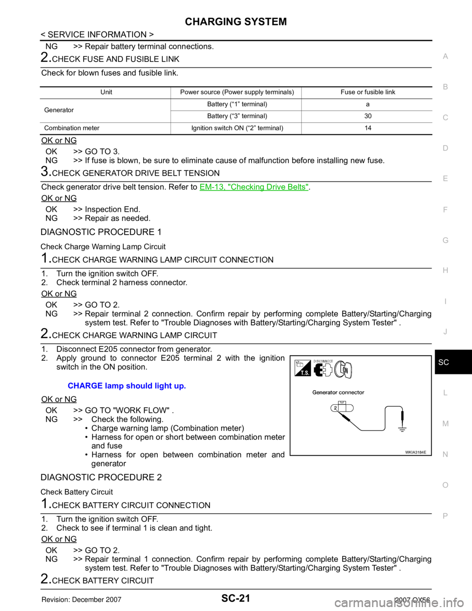
2.CHECK CHARGE WARNING LAMP CIRCUIT
1. Disconnect E205 connector from generator.
2. Apply ground to connector E205 terminal 2 with the ignition
switch in the ON position.
OK or NG
OK >> GO TO "WORK FLOW" .
NG >> Check the following.
• Charge warning lamp (Combination meter)
• Harness for open or short between combination meter
and fuse
• Harness for open between combination meter and
generator
DIAGNOSTIC PROCEDURE 2
Check Battery Circuit
1.CHECK BATTERY CIRCUIT CONNECTION
1. Turn the ignition switch OFF.
2. Check to see if terminal 1 is clean and tight.
OK or NG
OK >> GO TO 2.
NG >> Repair terminal 1 connection. Confirm repair by performing complete Battery/Starting/Charging
system test. Refer to "Trouble Diagnoses with Battery/Starting/Charging System Tester" .
2.CHECK BATTERY CIRCUIT
Unit Power source (Power supply terminals) Fuse or fusible link
GeneratorBattery (“1” terminal) a
Battery (“3” terminal) 30
Combination meter Ignition switch ON (“2” terminal) 14
CHARGE lamp should light up.
WKIA3184E