2007 INFINITI QX56 warning light
[x] Cancel search: warning lightPage 1052 of 3061
WARNING CHIME
DI-41
< SERVICE INFORMATION >
C
D
E
F
G
H
I
J
L
MA
B
DI
N
O
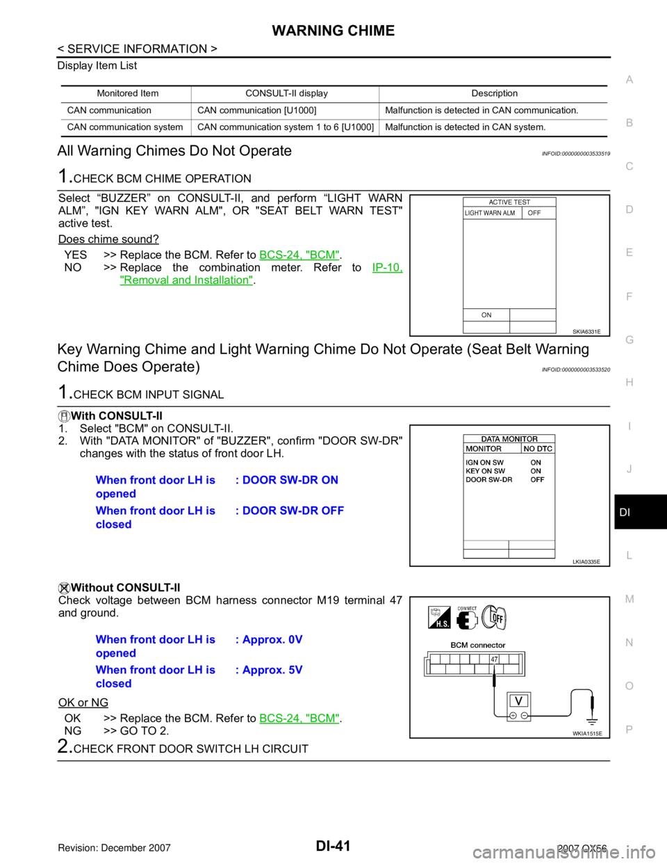
P Display Item List
All Warning Chimes Do Not OperateINFOID:0000000003533519
1.CHECK BCM CHIME OPERATION
Select “BUZZER” on CONSULT-II, and perform “LIGHT WARN
ALM”, "IGN KEY WARN ALM", OR "SEAT BELT WARN TEST"
active test.
Does chime sound?
YES >> Replace the BCM. Refer to BCS-24, "BCM".
NO >> Replace the combination meter. Refer to IP-10,
"Removal and Installation".
Key Warning Chime and Light Warning Chime Do Not Operate (Seat Belt Warning
Chime Does Operate)
INFOID:0000000003533520
1.CHECK BCM INPUT SIGNAL
With CONSULT-II
1. Select "BCM" on CONSULT-II.
2. With "DATA MONITOR" of "BUZZER", confirm "DOOR SW-DR"
changes with the status of front door LH.
Without CONSULT-II
Check voltage between BCM harness connector M19 terminal 47
and ground.
OK or NG
OK >> Replace the BCM. Refer to BCS-24, "BCM".
NG >> GO TO 2.
2.CHECK FRONT DOOR SWITCH LH CIRCUIT
Monitored Item CONSULT-II display Description
CAN communication CAN communication [U1000] Malfunction is detected in CAN communication.
CAN communication system CAN communication system 1 to 6 [U1000] Malfunction is detected in CAN system.
SKIA6331E
When front door LH is
opened: DOOR SW-DR ON
When front door LH is
closed: DOOR SW-DR OFF
LKIA0335E
When front door LH is
opened: Approx. 0V
When front door LH is
closed: Approx. 5V
WKIA1515E
Page 1053 of 3061
DI-42
< SERVICE INFORMATION >
WARNING CHIME
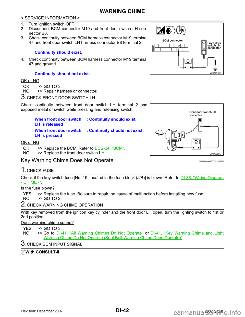
1. Turn ignition switch OFF.
2. Disconnect BCM connector M19 and front door switch LH con-
nector B8.
3. Check continuity between BCM harness connector M19 terminal
47 and front door switch LH harness connector B8 terminal 2.
4. Check continuity between BCM harness connector M19 terminal
47 and ground.
OK or NG
OK >> GO TO 3.
NG >> Repair harness or connector.
3.CHECK FRONT DOOR SWITCH LH
Check continuity between front door switch LH terminal 2 and
exposed metal of switch while pressing and releasing switch.
OK or NG
OK >> Replace the BCM. Refer to BCS-24, "BCM".
NG >> Replace the front door switch LH.
Key Warning Chime Does Not OperateINFOID:0000000003533521
1.CHECK FUSE
Check if the key switch fuse [No. 19, located in the fuse block (J/B)] is blown. Refer to DI-38, "
Wiring Diagram
- CHIME -".
Is the fuse blown?
YES >> Replace the fuse. Be sure to repair the cause of malfunction before installing new fuse.
NO >> GO TO 2.
2.CHECK WARNING CHIME OPERATION
With key removed from the ignition key cylinder and the front door LH open, turn the lighting switch to 1st or
2nd position.
Does warning chime sound?
YES >> GO TO 3.
NO >> Go to DI-41, "
All Warning Chimes Do Not Operate" or DI-41, "Key Warning Chime and Light
Warning Chime Do Not Operate (Seat Belt Warning Chime Does Operate)".
3.CHECK BCM INPUT SIGNAL
With CONSULT-IIContinuity should exist.
Continuity should not exist.
WKIA1516E
When front door switch
LH is released: Continuity should exist.
When front door switch
LH is pressed: Continuity should not exist.
WKIA2023E
Page 1055 of 3061
DI-44
< SERVICE INFORMATION >
WARNING CHIME
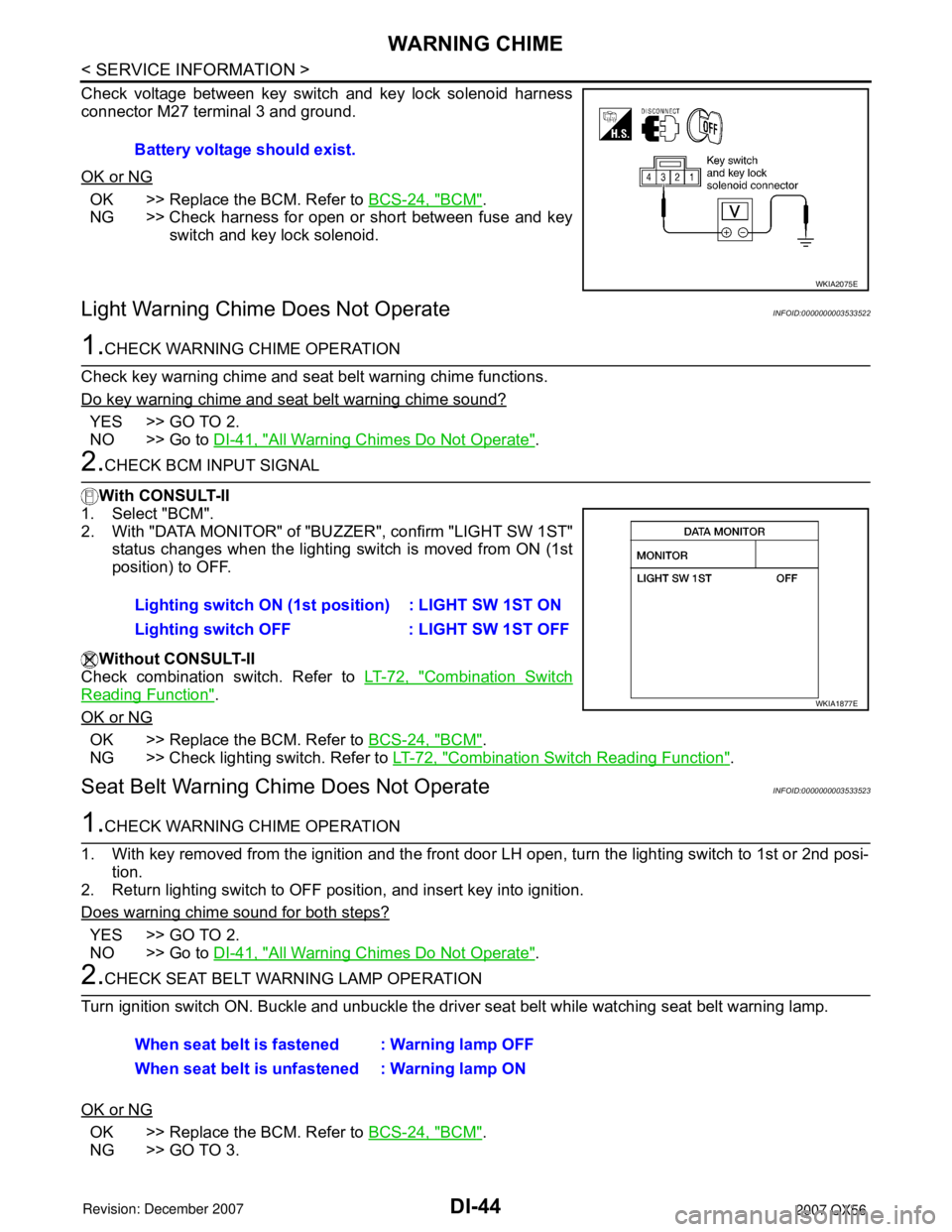
Check voltage between key switch and key lock solenoid harness
connector M27 terminal 3 and ground.
OK or NG
OK >> Replace the BCM. Refer to BCS-24, "BCM".
NG >> Check harness for open or short between fuse and key
switch and key lock solenoid.
Light Warning Chime Does Not OperateINFOID:0000000003533522
1.CHECK WARNING CHIME OPERATION
Check key warning chime and seat belt warning chime functions.
Do key warning chime and seat belt warning chime sound?
YES >> GO TO 2.
NO >> Go to DI-41, "
All Warning Chimes Do Not Operate".
2.CHECK BCM INPUT SIGNAL
With CONSULT-II
1. Select "BCM".
2. With "DATA MONITOR" of "BUZZER", confirm "LIGHT SW 1ST"
status changes when the lighting switch is moved from ON (1st
position) to OFF.
Without CONSULT-II
Check combination switch. Refer to LT-72, "
Combination Switch
Reading Function".
OK or NG
OK >> Replace the BCM. Refer to BCS-24, "BCM".
NG >> Check lighting switch. Refer to LT-72, "
Combination Switch Reading Function".
Seat Belt Warning Chime Does Not OperateINFOID:0000000003533523
1.CHECK WARNING CHIME OPERATION
1. With key removed from the ignition and the front door LH open, turn the lighting switch to 1st or 2nd posi-
tion.
2. Return lighting switch to OFF position, and insert key into ignition.
Does warning chime sound for both steps?
YES >> GO TO 2.
NO >> Go to DI-41, "
All Warning Chimes Do Not Operate".
2.CHECK SEAT BELT WARNING LAMP OPERATION
Turn ignition switch ON. Buckle and unbuckle the driver seat belt while watching seat belt warning lamp.
OK or NG
OK >> Replace the BCM. Refer to BCS-24, "BCM".
NG >> GO TO 3.Battery voltage should exist.
WKIA2075E
Lighting switch ON (1st position) : LIGHT SW 1ST ON
Lighting switch OFF : LIGHT SW 1ST OFF
WKIA1877E
When seat belt is fastened : Warning lamp OFF
When seat belt is unfastened : Warning lamp ON
Page 1100 of 3061
PRECAUTIONS
EC-17
< SERVICE INFORMATION >
C
D
E
F
G
H
I
J
K
L
MA
EC
N
P O
PRECAUTIONS
Precaution for Supplemental Restraint System (SRS) "AIR BAG" and "SEAT BELT
PRE-TENSIONER"
INFOID:0000000003531580
The Supplemental Restraint System such as “AIR BAG” and “SEAT BELT PRE-TENSIONER”, used along
with a front seat belt, helps to reduce the risk or severity of injury to the driver and front passenger for certain
types of collision. This system includes seat belt switch inputs and dual stage front air bag modules. The SRS
system uses the seat belt switches to determine the front air bag deployment, and may only deploy one front
air bag, depending on the severity of a collision and whether the front occupants are belted or unbelted.
Information necessary to service the system safely is included in the SRS and SB section of this Service Man-
ual.
WARNING:
• To avoid rendering the SRS inoperative, which could increase the risk of personal injury or death in
the event of a collision which would result in air bag inflation, all maintenance must be performed by
an authorized NISSAN/INFINITI dealer.
• Improper maintenance, including incorrect removal and installation of the SRS, can lead to personal
injury caused by unintentional activation of the system. For removal of Spiral Cable and Air Bag
Module, see the SRS section.
• Do not use electrical test equipment on any circuit related to the SRS unless instructed to in this
Service Manual. SRS wiring harnesses can be identified by yellow and/or orange harnesses or har-
ness connectors.
On Board Diagnosis (OBD) System of Engine and A/TINFOID:0000000003531581
The ECM has an on board diagnostic system. It will light up the malfunction indicator lamp (MIL) to warn the
driver of a malfunction causing emission deterioration.
CAUTION:
• Be sure to turn the ignition switch OFF and disconnect the negative battery cable before any repair
or inspection work. The open/short circuit of related switches, sensors, solenoid valves, etc. will
cause the MIL to light up.
• Be sure to connect and lock the connectors securely after work. A loose (unlocked) connector will
cause the MIL to light up due to the open circuit. (Be sure the connector is free from water, grease,
dirt, bent terminals, etc.)
• Certain systems and components, especially those related to OBD, may use a new style slide-lock-
ing type harness connector. For description and how to disconnect, refer to PG-66
.
• Be sure to route and secure the harnesses properly after work. The interference of the harness with
a bracket, etc. may cause the MIL to light up due to the short circuit.
• Be sure to connect rubber tubes properly after work. A misconnected or disconnected rubber tube
may cause the MIL to light up due to the malfunction of the EVAP system or fuel injection system,
etc.
• Be sure to erase the unnecessary malfunction information (repairs completed) from the ECM and
TCM (Transmission control module) before returning the vehicle to the customer.
PrecautionINFOID:0000000003531582
•Always use a 12 volt battery as power source.
•Do not attempt to disconnect battery cables while engine is
running.
•Before connecting or disconnecting the ECM harness con-
nector, turn ignition switch OFF and disconnect negative bat-
tery cable. Failure to do so may damage the ECM because
battery voltage is applied to ECM even if ignition switch is
turned OFF.
•Before removing parts, turn ignition switch OFF and then dis-
connect negative battery cable.
SEF289H
Page 1146 of 3061
ON BOARD DIAGNOSTIC (OBD) SYSTEM
EC-63
< SERVICE INFORMATION >
C
D
E
F
G
H
I
J
K
L
MA
EC
N
P O
Actual work procedures are explained using a DTC as an example. Be careful so that not only the DTC, but all
of the data listed above, are cleared from the ECM memory during work procedures.
Malfunction Indicator Lamp (MIL)INFOID:0000000003531607
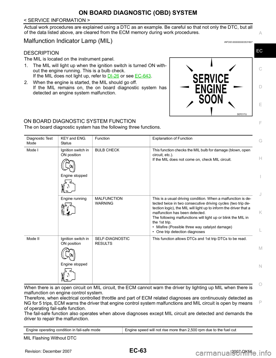
DESCRIPTION
The MIL is located on the instrument panel.
1. The MIL will light up when the ignition switch is turned ON with-
out the engine running. This is a bulb check.
If the MIL does not light up, refer to DI-26
or see EC-643.
2. When the engine is started, the MIL should go off.
If the MIL remains on, the on board diagnostic system has
detected an engine system malfunction.
ON BOARD DIAGNOSTIC SYSTEM FUNCTION
The on board diagnostic system has the following three functions.
When there is an open circuit on MIL circuit, the ECM cannot warn the driver by lighting up MIL when there is
malfunction on engine control system.
Therefore, when electrical controlled throttle and part of ECM related diagnoses are continuously detected as
NG for 5 trips, ECM warns the driver that engine control system malfunctions and MIL circuit is open by means
of operating fail-safe function.
The fail-safe function also operates when above diagnoses except MIL circuit are detected and demands the
driver to repair the malfunction.
MIL Flashing Without DTC
SEF217U
Diagnostic Test
ModeKEY and ENG.
Sta tusFunction Explanation of Function
Mode I Ignition switch in
ON position
Engine stoppedBULB CHECK This function checks the MIL bulb for damage (blown, open
circuit, etc.).
If the MIL does not come on, check MIL circuit.
Engine running MALFUNCTION
WARNINGThis is a usual driving condition. When a malfunction is de-
tected twice in two consecutive driving cycles (two trip de-
tection logic), the MIL will light up to inform the driver that a
malfunction has been detected.
The following malfunctions will light up or blink the MIL in
the 1st trip.
• Misfire (Possible three way catalyst damage)
• One trip detection diagnoses
Mode II Ignition switch in
ON position
Engine stoppedSELF-DIAGNOSTIC
RESULTSThis function allows DTCs and 1st trip DTCs to be read.
Engine operating condition in fail-safe mode Engine speed will not rise more than 2,500 rpm due to the fuel cut
Page 1968 of 3061
GI-2
< SERVICE INFORMATION >
PRECAUTIONS
SERVICE INFORMATION
PRECAUTIONS
DescriptionINFOID:0000000003531468
Observe the following precautions to ensure safe and proper servicing. These precautions are not
described in each individual section.
Precaution for Supplemental Restraint System (SRS) "AIR BAG" and "SEAT BELT
PRE-TENSIONER"
INFOID:0000000003531469
The Supplemental Restraint System such as “AIR BAG” and “SEAT BELT PRE-TENSIONER”, used along
with a front seat belt, helps to reduce the risk or severity of injury to the driver and front passenger for certain
types of collision. This system includes seat belt switch inputs and dual stage front air bag modules. The SRS
system uses the seat belt switches to determine the front air bag deployment, and may only deploy one front
air bag, depending on the severity of a collision and whether the front occupants are belted or unbelted.
Information necessary to service the system safely is included in the SRS and SB section of this Service Man-
ual.
WARNING:
• To avoid rendering the SRS inoperative, which could increase the risk of personal injury or death in
the event of a collision which would result in air bag inflation, all maintenance must be performed by
an authorized NISSAN/INFINITI dealer.
• Improper maintenance, including incorrect removal and installation of the SRS, can lead to personal
injury caused by unintentional activation of the system. For removal of Spiral Cable and Air Bag
Module, see the SRS section.
• Do not use electrical test equipment on any circuit related to the SRS unless instructed to in this
Service Manual. SRS wiring harnesses can be identified by yellow and/or orange harnesses or har-
ness connectors.
Precaution for NVIS/IVIS (NISSAN/INFINITI VEHICLE IMMOBILIZER SYSTEM -
NATS) (If Equipped)
INFOID:0000000003531470
NVIS/IVIS (NATS) will immobilize the engine if someone tries to start it without the registered key of NVIS/IVIS
(NATS).
Both of the originally supplied ignition key IDs have been NVIS/IVIS (NATS) registered.
The security indicator is located on the instrument panel. The indicator blinks when the immobilizer system is
functioning.
Therefore, NVIS/IVIS (NATS) warns outsiders that the vehicle is equipped with the anti-theft system.
• When NVIS/IVIS (NATS) detects trouble, the security indicator lamp lights up while ignition switch is in "ON"
position.
This lighting up indicates that the anti-theft is not functioning, so prompt service is required.
• When servicing NVIS/IVIS (NATS) (trouble diagnoses, system initialization and additional registration of
other NVIS/IVIS (NATS) ignition key IDs), CONSULT-II hardware and CONSULT-II NVIS/IVIS (NATS) soft-
ware is necessary.
Regarding the procedures of NVIS/IVIS (NATS) initialization and NVIS/IVIS (NATS) ignition key ID registra-
tion, refer to CONSULT-II operation manual, NVIS/IVIS (NATS).
Therefore, CONSULT-II NVIS/IVIS (NATS) software (program card and operation manual) must be kept
strictly confidential to maintain the integrity of the anti-theft function.
• When servicing NVIS/IVIS (NATS) (trouble diagnoses, system initialization and additional registration of
other NVIS/IVIS (NATS) ignition key IDs), it may be necessary to re-register original key identification.
Therefore, be sure to receive all keys from vehicle owner. A maximum of four or five key IDs can be regis-
tered into NVIS/IVIS (NATS).
• When failing to start the engine first time using the key of NVIS/IVIS (NATS), start as follows.
1. Leave the ignition key in "ON" position for approximately 5 seconds.
2. Turn ignition key to "OFF" or "LOCK" position and wait approximately 5 seconds.
3. Repeat step 1 and 2 again.
4. Restart the engine while keeping the key separate from any others on key-chain.
Page 2002 of 3061
![INFINITI QX56 2007 Factory Service Manual GI-36
< SERVICE INFORMATION >
CONSULT-II CHECKING SYSTEM
*2: IVIS (NATS) [Infiniti Vehicle Immobilizer System (Nissan Anti-Theft System)].
*3: This system is shown with IVIS (NATS) using program card INFINITI QX56 2007 Factory Service Manual GI-36
< SERVICE INFORMATION >
CONSULT-II CHECKING SYSTEM
*2: IVIS (NATS) [Infiniti Vehicle Immobilizer System (Nissan Anti-Theft System)].
*3: This system is shown with IVIS (NATS) using program card](/manual-img/42/57029/w960_57029-2001.png)
GI-36
< SERVICE INFORMATION >
CONSULT-II CHECKING SYSTEM
*2: IVIS (NATS) [Infiniti Vehicle Immobilizer System (Nissan Anti-Theft System)].
*3: This system is shown with IVIS (NATS) using program card AEN06B or later.
Nickel Metal Hydride Battery ReplacementINFOID:0000000003531492
CONSULT-II contains a nickel metal hydride battery. When replacing the battery obey the following:
WARNING:
Replace the nickel metal hydride battery with Genuine CONSULT-II battery only. Use of another bat-
tery may present a risk of fire or explosion. The battery may present a fire or chemical burn hazard
ifmistreated. Do not recharge, disassemble or dispose of in fire.
Keep the battery out of reach of children and discard used battery conforming to the local regulations.
Checking EquipmentINFOID:0000000003531493
When ordering the below equipment, contact your NISSAN distributor.
CAUTION:
• Previous CONSULT-II “I” and “Y” DLC-I and DLC-II cables should NOT be used anymore because
their DDL connector pins can be damaged during cable swapping.
• If CONSULT-II is used with no connection of CONSULT-II CONVERTER, malfunctions might be
detected in self- diagnosis depending on control unit which carries out CAN communication.
• If CONSULT-II CONVERTER is not connected with CONSULT-II, the vehicle enters “FAIL SAFE
MODE” which will “LIGHT UP the HEAD LIGHT” and /or “COOLING FAN ROTATING” when CONSULT-
II is started.
NOTE:
• The CONSULT-II must be used in conjunction with a program card.
CONSULT-II does not require loading (Initialization) procedure.
• Be sure the CONSULT-II is turned OFF before installing or removing a program card.
CONSULT-II Start ProcedureINFOID:0000000003531494
NOTE:
Turning ignition switch off when performing CAN diagnosis could cause CAN memory to be erased.
1. Connect CONSULT-II and CONSULT-II CONVERTER to the
data link connector.
Tool name Description
NISSAN CONSULT-II (J-44200)
1. CONSULT-II unit (Tester internal soft: Resi-
dent Version 3.4.0) and accessories.
2. Program card UED06E-1 and AEN06B (for
NATS) or later, to confirm the best combina-
tion of these software, refer to CONSULT-II
Operation Manual.
3. CONSULT-II CONVERTER.
4. CONSULT-II pigtail cable.
SAIA0363E
PAIA0070E
Page 2176 of 3061
![INFINITI QX56 2007 Factory Service Manual TROUBLE DIAGNOSIS
LAN-45
< SERVICE INFORMATION >[CAN]
C
D
E
F
G
H
I
J
L
MA
B
LAN
N
O
P
Engine speed signal T R R R R R R
Engine status signal T R
Fuel consumption monitor signalTR
RT
ICC steering swit INFINITI QX56 2007 Factory Service Manual TROUBLE DIAGNOSIS
LAN-45
< SERVICE INFORMATION >[CAN]
C
D
E
F
G
H
I
J
L
MA
B
LAN
N
O
P
Engine speed signal T R R R R R R
Engine status signal T R
Fuel consumption monitor signalTR
RT
ICC steering swit](/manual-img/42/57029/w960_57029-2175.png)
TROUBLE DIAGNOSIS
LAN-45
< SERVICE INFORMATION >[CAN]
C
D
E
F
G
H
I
J
L
MA
B
LAN
N
O
P
Engine speed signal T R R R R R R
Engine status signal T R
Fuel consumption monitor signalTR
RT
ICC steering switch signal T R
Malfunction indicator lamp signal T R
Wide open throttle position signal T R
A/T CHECK indicator lamp signal T R
A/T fluid temperature sensor signal T R
A/T position indicator lamp signal T R R
A/T self-diagnosis signal R T
Current gear position signal T R R
Output shaft revolution signal R T R
P range signal T R R R R
Turbine revolution signal R T R
ICC sensor signal T R
Buzzer output signalTR
TR
ICC OD cancel request signal R R T
ICC operation signal R R T
ICC system display signal T R
System setting signalTR
RT
A/C switch signal R T R
Blower fan motor switch signal R T
Day time running light request signal T R R
Door switch signal R T R R R
Front fog light request signal T R
Front wiper request signal R T R
High beam request signal T R R
Horn chirp signal T R
Ignition switch signal R T R
Key fob door unlock signal R T
Key fob ID signal R T
Key switch signal R T
Low beam request signal T R
Position light request signal T R R
Rear window defogger switch signal T R R
Sleep wake up signal R T R R
Theft warning horn request signal T R
Tire pressure data signal T R
Tire pressure signal T R R
Turn indicator signal T RSignal name/Connecting unit
ECM
TCM
LASER
ICC
ADP
BCM
DISP
HVAC
M&A
STRG
ABS
IPDM-E