2007 INFINITI QX56 oil type
[x] Cancel search: oil typePage 1966 of 3061
FSU-20
< SERVICE INFORMATION >
SERVICE DATA AND SPECIFICATIONS (SDS)
*4: Target value 37° 44′ (37.73°)
*5: Target value 33° 29′ (33.48°)
*6: Some vehicles may be equipped with straight (non-adjustable) lower link bolts and washers. in order to adjust camber and caster on
these vehicles, first replace the lower link bolts and washers with adjustable (cam) bolts and washers.
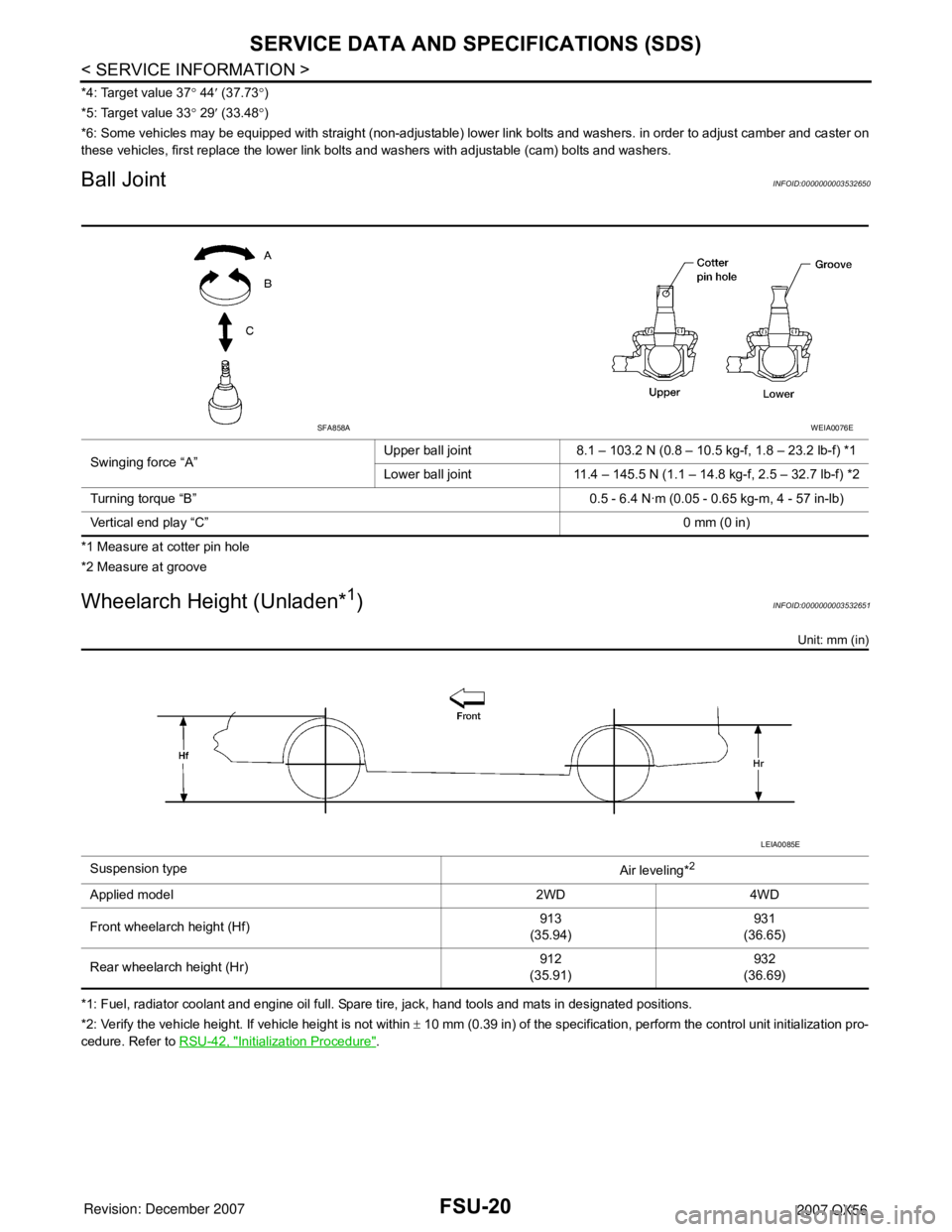
Ball JointINFOID:0000000003532650
*1 Measure at cotter pin hole
*2 Measure at groove
Wheelarch Height (Unladen*1)INFOID:0000000003532651
Unit: mm (in)
*1: Fuel, radiator coolant and engine oil full. Spare tire, jack, hand tools and mats in designated positions.
*2: Verify the vehicle height. If vehicle height is not within ± 10 mm (0.39 in) of the specification, perform the control unit initialization pro-
cedure. Refer to RSU-42, "
Initialization Procedure". Swinging force “A”Upper ball joint 8.1 – 103.2 N (0.8 – 10.5 kg-f, 1.8 – 23.2 lb-f) *1
Lower ball joint 11.4 – 145.5 N (1.1 – 14.8 kg-f, 2.5 – 32.7 lb-f) *2
Turning torque “B” 0.5 - 6.4 N·m (0.05 - 0.65 kg-m, 4 - 57 in-lb)
Vertical end play “C”0 mm (0 in)
SFA858AWEIA0076E
Suspension type
Air leveling*2
Applied model 2WD 4WD
Front wheelarch height (Hf)913
(35.94)931
(36.65)
Rear wheelarch height (Hr)912
(35.91)932
(36.69)
LEIA0085E
Page 1999 of 3061
SERVICE INFORMATION FOR ELECTRICAL INCIDENT
GI-33
< SERVICE INFORMATION >
C
D
E
F
G
H
I
J
K
L
MB
GI
N
O
P
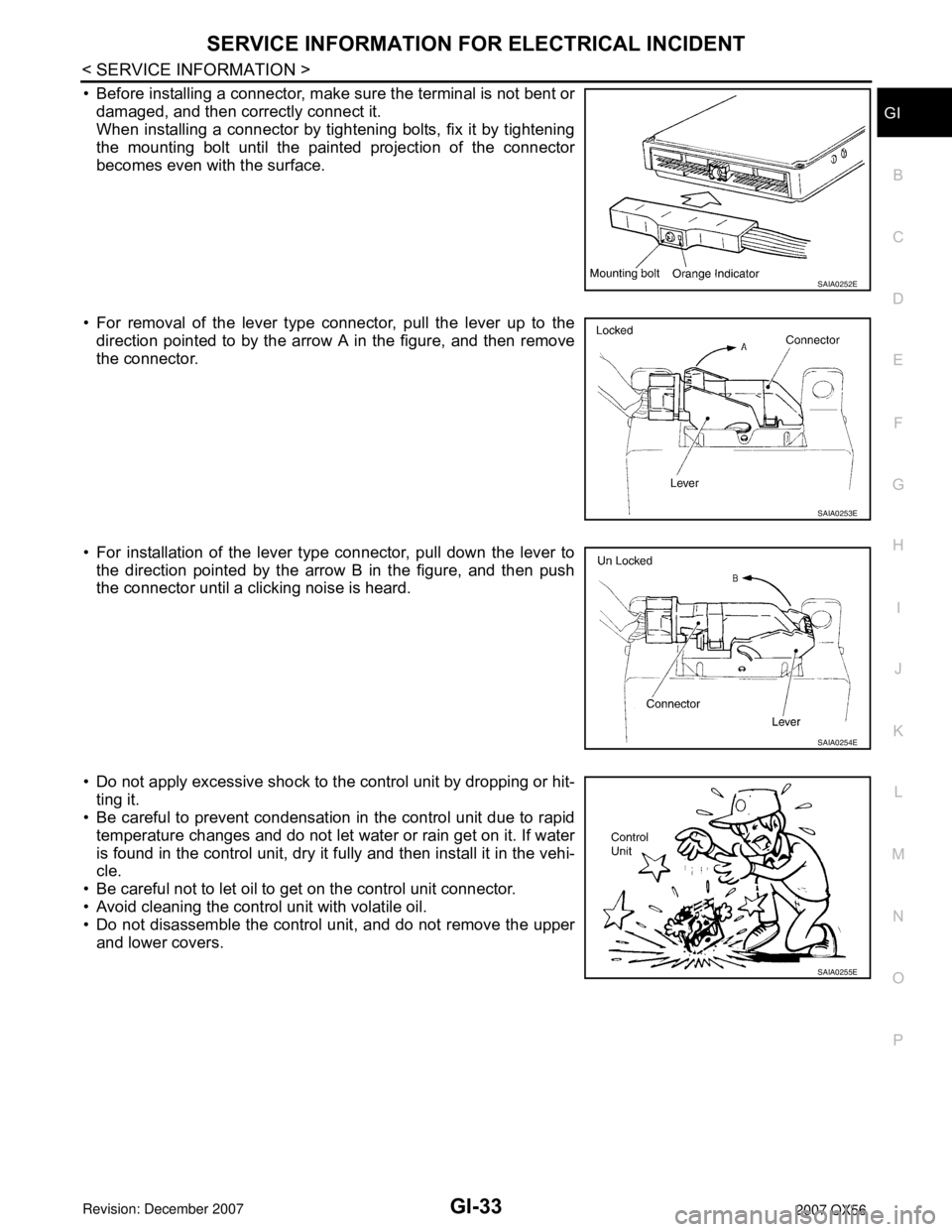
• Before installing a connector, make sure the terminal is not bent or
damaged, and then correctly connect it.
When installing a connector by tightening bolts, fix it by tightening
the mounting bolt until the painted projection of the connector
becomes even with the surface.
• For removal of the lever type connector, pull the lever up to the
direction pointed to by the arrow A in the figure, and then remove
the connector.
• For installation of the lever type connector, pull down the lever to
the direction pointed by the arrow B in the figure, and then push
the connector until a clicking noise is heard.
• Do not apply excessive shock to the control unit by dropping or hit-
ting it.
• Be careful to prevent condensation in the control unit due to rapid
temperature changes and do not let water or rain get on it. If water
is found in the control unit, dry it fully and then install it in the vehi-
cle.
• Be careful not to let oil to get on the control unit connector.
• Avoid cleaning the control unit with volatile oil.
• Do not disassemble the control unit, and do not remove the upper
and lower covers.
SAIA0252E
SAIA0253E
SAIA0254E
SAIA0255E
Page 2014 of 3061
GI-48
< SERVICE INFORMATION >
IDENTIFICATION INFORMATION
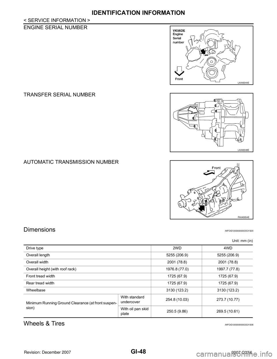
ENGINE SERIAL NUMBER
TRANSFER SERIAL NUMBER
AUTOMATIC TRANSMISSION NUMBER
DimensionsINFOID:0000000003531505
Unit: mm (in)
Wheels & TiresINFOID:0000000003531506
LAIA0044E
LAIA0048E
PAIA0054E
Drive type2WD 4WD
Overall length 5255 (206.9) 5255 (206.9)
Overall width 2001 (78.8) 2001 (78.8)
Overall height (with roof rack) 1976.8 (77.0) 1997.7 (77.8)
Front tread width 1725 (67.9) 1725 (67.9)
Rear tread width 1725 (67.9) 1725 (67.9)
Wheelbase 3130 (123.2) 3130 (123.2)
Minimum Running Ground Clearance (at front suspen-
sion)With standard
undercover254.8 (10.03) 273.7 (10.77)
With oil pan skid
plate250.5 (9.86) 269.5 (10.61)
Page 2211 of 3061
LT-4
< SERVICE INFORMATION >
PRECAUTIONS
SERVICE INFORMATION
PRECAUTIONS
Precaution for Supplemental Restraint System (SRS) "AIR BAG" and "SEAT BELT
PRE-TENSIONER"
INFOID:0000000003533330
The Supplemental Restraint System such as “AIR BAG” and “SEAT BELT PRE-TENSIONER”, used along
with a front seat belt, helps to reduce the risk or severity of injury to the driver and front passenger for certain
types of collision. This system includes seat belt switch inputs and dual stage front air bag modules. The SRS
system uses the seat belt switches to determine the front air bag deployment, and may only deploy one front
air bag, depending on the severity of a collision and whether the front occupants are belted or unbelted.
Information necessary to service the system safely is included in the SRS and SB section of this Service Man-
ual.
WARNING:
• To avoid rendering the SRS inoperative, which could increase the risk of personal injury or death in
the event of a collision which would result in air bag inflation, all maintenance must be performed by
an authorized NISSAN/INFINITI dealer.
• Improper maintenance, including incorrect removal and installation of the SRS, can lead to personal
injury caused by unintentional activation of the system. For removal of Spiral Cable and Air Bag
Module, see the SRS section.
• Do not use electrical test equipment on any circuit related to the SRS unless instructed to in this
Service Manual. SRS wiring harnesses can be identified by yellow and/or orange harnesses or har-
ness connectors.
General precautions for service operationsINFOID:0000000003533331
• Never work with wet hands.
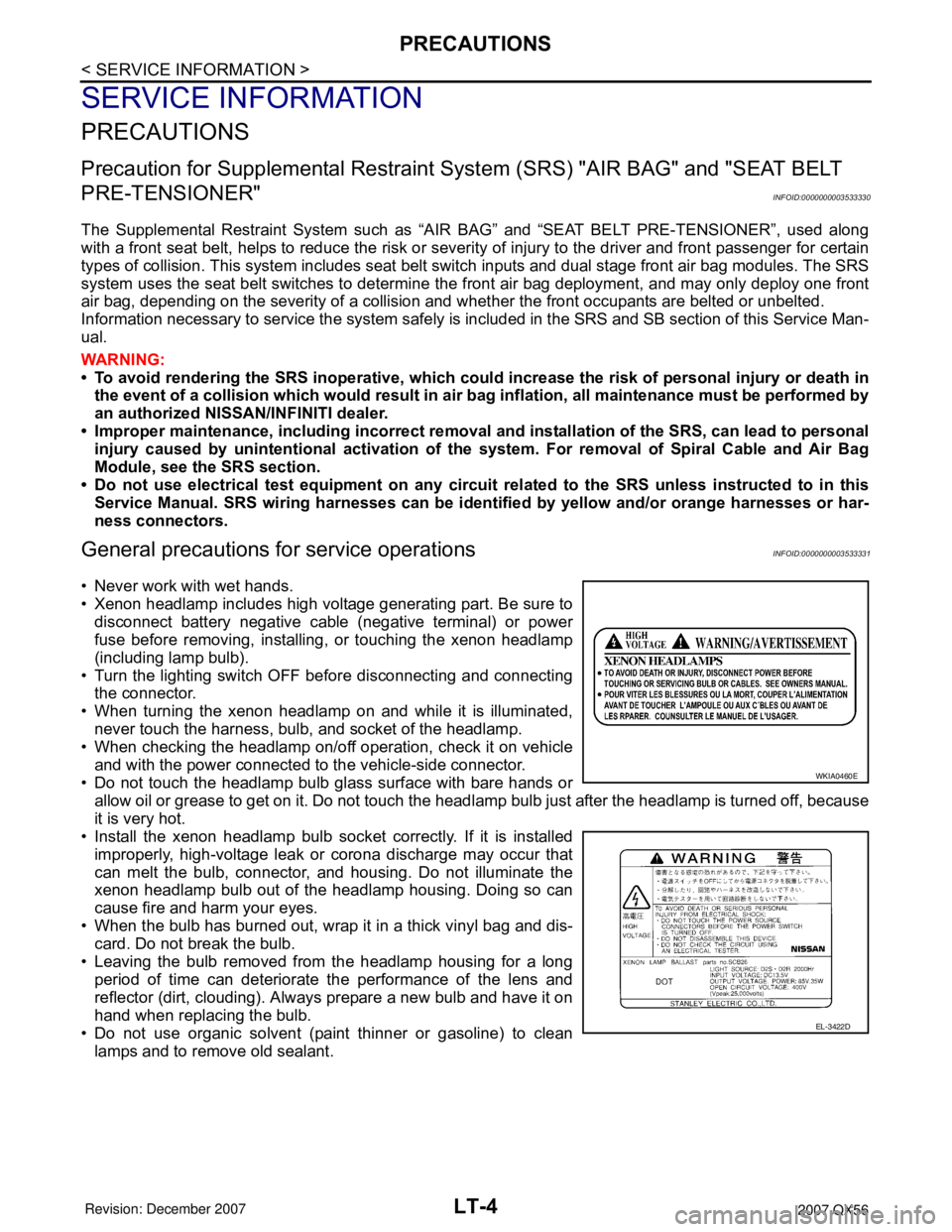
• Xenon headlamp includes high voltage generating part. Be sure to
disconnect battery negative cable (negative terminal) or power
fuse before removing, installing, or touching the xenon headlamp
(including lamp bulb).
• Turn the lighting switch OFF before disconnecting and connecting
the connector.
• When turning the xenon headlamp on and while it is illuminated,
never touch the harness, bulb, and socket of the headlamp.
• When checking the headlamp on/off operation, check it on vehicle
and with the power connected to the vehicle-side connector.
• Do not touch the headlamp bulb glass surface with bare hands or
allow oil or grease to get on it. Do not touch the headlamp bulb just after the headlamp is turned off, because
it is very hot.
• Install the xenon headlamp bulb socket correctly. If it is installed
improperly, high-voltage leak or corona discharge may occur that
can melt the bulb, connector, and housing. Do not illuminate the
xenon headlamp bulb out of the headlamp housing. Doing so can
cause fire and harm your eyes.
• When the bulb has burned out, wrap it in a thick vinyl bag and dis-
card. Do not break the bulb.
• Leaving the bulb removed from the headlamp housing for a long
period of time can deteriorate the performance of the lens and
reflector (dirt, clouding). Always prepare a new bulb and have it on
hand when replacing the bulb.
• Do not use organic solvent (paint thinner or gasoline) to clean
lamps and to remove old sealant.
WKIA0460E
EL-3422D
Page 2213 of 3061

LT-6
< SERVICE INFORMATION >
HEADLAMP (FOR USA)
• to BCM terminal 38.
Ground is supplied
• to BCM terminal 67
• through grounds M57, M61 and M79, and
• to IPDM E/R terminals 38 and 59
• through grounds E9, E15 and E24.
Low Beam Operation
With the lighting switch in 2ND position, the BCM receives input requesting the headlamps to illuminate. This
input is communicated to the IPDM E/R across the CAN communication lines. The CPU of the IPDM E/R con-
trols the headlamp low relay coil. When energized, this relay directs power
• through 15A fuse (No. 41, located in the IPDM E/R)
• through IPDM E/R terminal 54
• to front combination lamp RH terminal 5, and
• through 15A fuse (No. 40, located in the IPDM E/R)
• through IPDM E/R terminal 52
• to front combination lamp LH terminal 5.
Ground is supplied
• to front combination lamp LH and RH terminal 1
• through grounds E9, E15 and E24.
With power and ground supplied, low beam headlamps illuminate.
High Beam Operation/Flash-to-Pass Operation
With the lighting switch in 2ND position and placed in HIGH or PASS position, the BCM receives input request-
ing the headlamp high beams to illuminate. This input is communicated to the IPDM E/R across the CAN com-
munication lines. The CPU of the combination meter controls the ON/OFF status of the HIGH BEAM indicator.
The CPU of the IPDM E/R controls the headlamp high relay coil. When energized, this relay directs power
• through 10A fuse (No. 34, located in the IPDM E/R)
• through IPDM E/R terminal 56
• to front combination lamp RH terminal 6, and
• through 10A fuse (No. 35, located in the IPDM E/R)
• through IPDM E/R terminal 55
• to front combination lamp LH terminal 6.
Ground is supplied
• to front combination lamp LH and RH terminal 2
• through grounds E9, E15 and E24.
With power and ground supplied, the high beam headlamps illuminate.
XENON HEADLAMP
Xenon type headlamp is adopted to the low beam headlamps. Xenon bulbs do not use a filament. Instead,
they produce light when a high voltage current is passed between two tungsten electrodes through a mixture
of xenon (an inert gas) and certain other metal halides. In addition to added lighting power, electronic control
of the power supply gives the headlamps stable quality and tone color.
Following are some of the many advantages of the xenon type headlamp.
• The light produced by the headlamps is a white color comparable to sunlight that is easy on the eyes.
• Light output is nearly double that of halogen headlamps, affording increased area of illumination.
• The light features a high relative spectral distribution at wavelengths to which the human eye is most sensi-
tive. This means that even in the rain, more light is reflected back from the road surface toward the vehicle,
for added visibility.
• Power consumption is approximately 25 percent less than halogen headlamps, reducing battery load.
BATTERY SAVER CONTROL
When the combination switch (lighting switch) is in the 2ND position (ON), and the ignition switch is turned
from ON or ACC to OFF, the battery saver control feature is activated.
Under this condition, the headlamps remain illuminated for 5 minutes, unless the combination switch (lighting
switch) position is changed. If the combination switch (lighting switch) position is changed, then the headlamps
are turned off.
AUTO LIGHT OPERATION
Refer to LT-34, "System Description" for auto light operation.
VEHICLE SECURITY SYSTEM (PANIC ALARM)
Page 2262 of 3061
FRONT FOG LAMP
LT-55
< SERVICE INFORMATION >
C
D
E
F
G
H
I
J
L
MA
B
LT
N
O
P
Aiming AdjustmentINFOID:0000000003533400
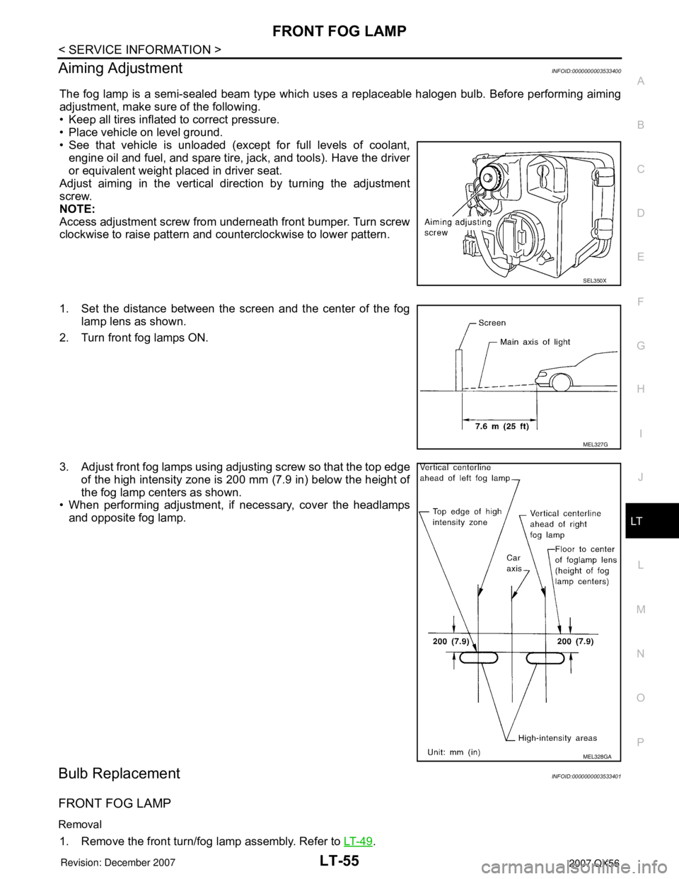
The fog lamp is a semi-sealed beam type which uses a replaceable halogen bulb. Before performing aiming
adjustment, make sure of the following.
• Keep all tires inflated to correct pressure.
• Place vehicle on level ground.
• See that vehicle is unloaded (except for full levels of coolant,
engine oil and fuel, and spare tire, jack, and tools). Have the driver
or equivalent weight placed in driver seat.
Adjust aiming in the vertical direction by turning the adjustment
screw.
NOTE:
Access adjustment screw from underneath front bumper. Turn screw
clockwise to raise pattern and counterclockwise to lower pattern.
1. Set the distance between the screen and the center of the fog
lamp lens as shown.
2. Turn front fog lamps ON.
3. Adjust front fog lamps using adjusting screw so that the top edge
of the high intensity zone is 200 mm (7.9 in) below the height of
the fog lamp centers as shown.
• When performing adjustment, if necessary, cover the headlamps
and opposite fog lamp.
Bulb ReplacementINFOID:0000000003533401
FRONT FOG LAMP
Removal
1. Remove the front turn/fog lamp assembly. Refer to LT- 4 9.
SEL350X
MEL327G
MEL328GA
Page 2263 of 3061
LT-56
< SERVICE INFORMATION >
FRONT FOG LAMP
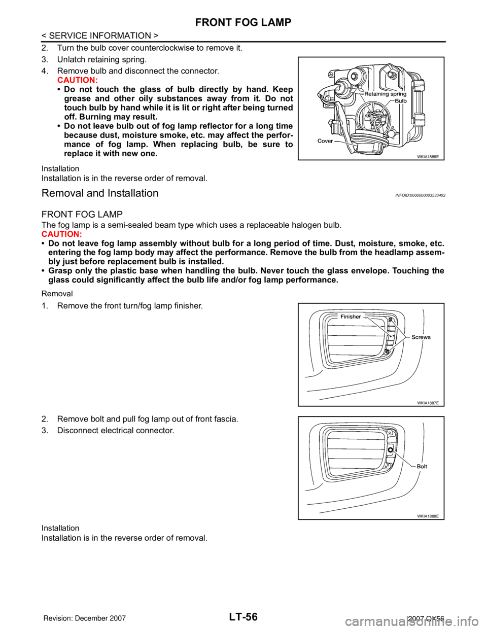
2. Turn the bulb cover counterclockwise to remove it.
3. Unlatch retaining spring.
4. Remove bulb and disconnect the connector.
CAUTION:
• Do not touch the glass of bulb directly by hand. Keep
grease and other oily substances away from it. Do not
touch bulb by hand while it is lit or right after being turned
off. Burning may result.
• Do not leave bulb out of fog lamp reflector for a long time
because dust, moisture smoke, etc. may affect the perfor-
mance of fog lamp. When replacing bulb, be sure to
replace it with new one.
Installation
Installation is in the reverse order of removal.
Removal and InstallationINFOID:0000000003533402
FRONT FOG LAMP
The fog lamp is a semi-sealed beam type which uses a replaceable halogen bulb.
CAUTION:
• Do not leave fog lamp assembly without bulb for a long period of time. Dust, moisture, smoke, etc.
entering the fog lamp body may affect the performance. Remove the bulb from the headlamp assem-
bly just before replacement bulb is installed.
• Grasp only the plastic base when handling the bulb. Never touch the glass envelope. Touching the
glass could significantly affect the bulb life and/or fog lamp performance.
Removal
1. Remove the front turn/fog lamp finisher.
2. Remove bolt and pull fog lamp out of front fascia.
3. Disconnect electrical connector.
Installation
Installation is in the reverse order of removal.
WKIA1886E
WKIA1887E
WKIA1888E
Page 2368 of 3061
MA-6
< SERVICE INFORMATION >
PERIODIC MAINTENANCE
PERIODIC MAINTENANCE
Introduction of Periodic MaintenanceINFOID:0000000003533860
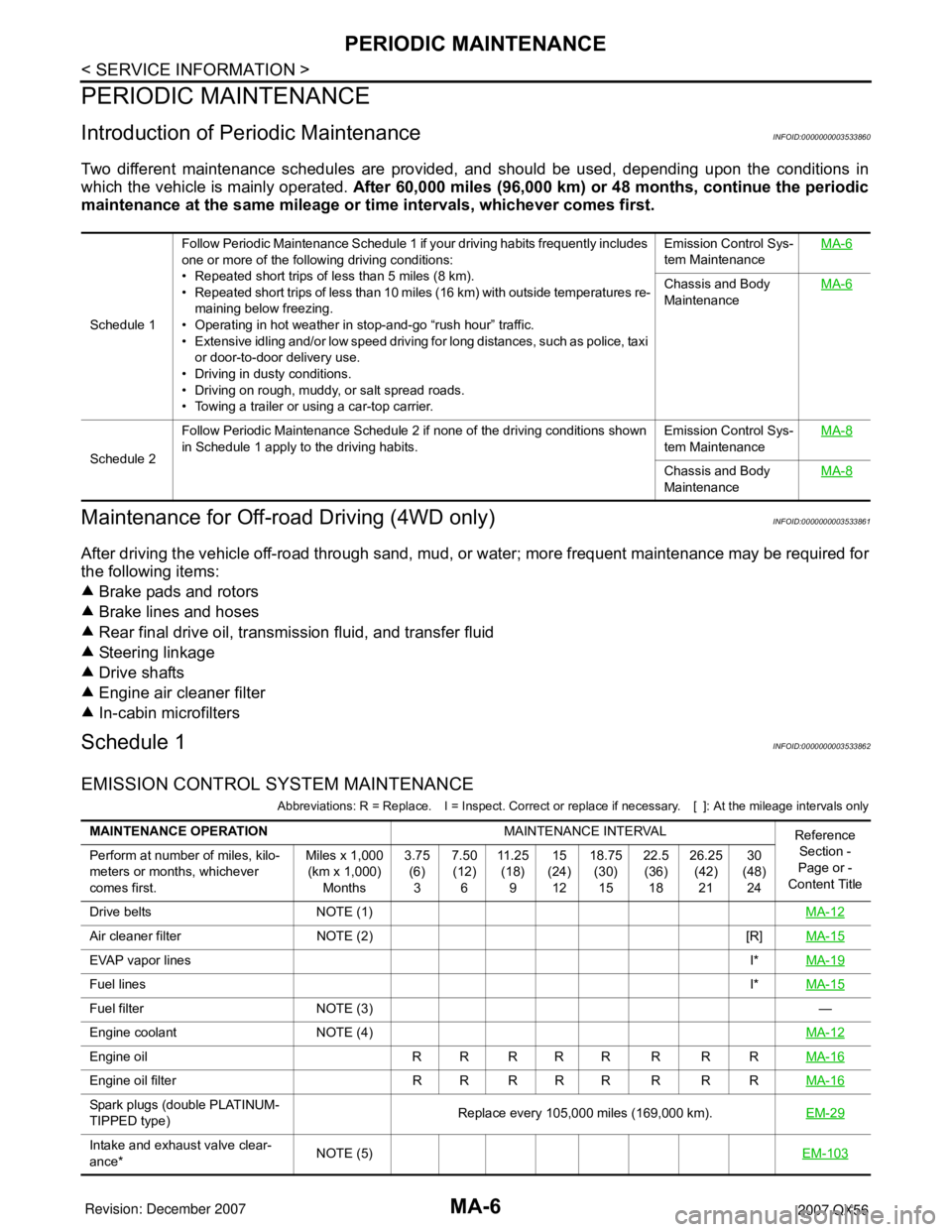
Two different maintenance schedules are provided, and should be used, depending upon the conditions in
which the vehicle is mainly operated. After 60,000 miles (96,000 km) or 48 months, continue the periodic
maintenance at the same mileage or time intervals, whichever comes first.
Maintenance for Off-road Driving (4WD only)INFOID:0000000003533861
After driving the vehicle off-road through sand, mud, or water; more frequent maintenance may be required for
the following items:
Brake pads and rotors
Brake lines and hoses
Rear final drive oil, transmission fluid, and transfer fluid
Steering linkage
Drive shafts
Engine air cleaner filter
In-cabin microfilters
Schedule 1INFOID:0000000003533862
EMISSION CONTROL SYSTEM MAINTENANCE
Abbreviations: R = Replace. I = Inspect. Correct or replace if necessary. [ ]: At the mileage intervals only
Schedule 1Follow Periodic Maintenance Schedule 1 if your driving habits frequently includes
one or more of the following driving conditions:
• Repeated short trips of less than 5 miles (8 km).
• Repeated short trips of less than 10 miles (16 km) with outside temperatures re-
maining below freezing.
• Operating in hot weather in stop-and-go “rush hour” traffic.
• Extensive idling and/or low speed driving for long distances, such as police, taxi
or door-to-door delivery use.
• Driving in dusty conditions.
• Driving on rough, muddy, or salt spread roads.
• Towing a trailer or using a car-top carrier.Emission Control Sys-
tem MaintenanceMA-6
Chassis and Body
MaintenanceMA-6
Schedule 2Follow Periodic Maintenance Schedule 2 if none of the driving conditions shown
in Schedule 1 apply to the driving habits.Emission Control Sys-
tem MaintenanceMA-8Chassis and Body
MaintenanceMA-8
MAINTENANCE OPERATIONMAINTENANCE INTERVAL
Reference
Section -
Page or -
Content Title Perform at number of miles, kilo-
meters or months, whichever
comes first.Miles x 1,000
(km x 1,000)
Months3.75
(6)
37.50
(12)
611 . 2 5
(18)
915
(24)
1218.75
(30)
1522.5
(36)
1826.25
(42)
2130
(48)
24
Drive belts NOTE (1)MA-12
Air cleaner filter NOTE (2) [R]MA-15
EVAP vapor linesI*MA-19
Fuel linesI*MA-15
Fuel filter NOTE (3)—
Engine coolant NOTE (4)MA-12
Engine oil R R R R R R R RMA-16
Engine oil filter R R R R R R R RMA-16
Spark plugs (double PLATINUM-
TIPPED type)Replace every 105,000 miles (169,000 km).EM-29
Intake and exhaust valve clear-
ance*NOTE (5)EM-103