2007 INFINITI QX56 oil type
[x] Cancel search: oil typePage 1773 of 3061
PRECAUTIONSEM-3
< SERVICE INFORMATION >
C
DE
F
G H
I
J
K L
M A
EM
NP
O
SERVICE INFORMATION
PRECAUTIONS
Precaution for Supplemental
Restraint System (SRS) "AIR BAG" and "SEAT BELT
PRE-TENSIONER"
INFOID:0000000003531508
The Supplemental Restraint System such as “A IR BAG” and “SEAT BELT PRE-TENSIONER”, used along
with a front seat belt, helps to reduce the risk or severi ty of injury to the driver and front passenger for certain
types of collision. This system includes seat belt switch inputs and dual stage front air bag modules. The SRS
system uses the seat belt switches to determine the front air bag deployment, and may only deploy one front
air bag, depending on the severity of a collision and w hether the front occupants are belted or unbelted.
Information necessary to service the system safely is included in the SRS and SB section of this Service Man-
ual.
WARNING:
• To avoid rendering the SRS inoper ative, which could increase the risk of personal injury or death in
the event of a collision which would result in air bag inflation, all maintenance must be performed by
an authorized NISSAN/INFINITI dealer.
• Improper maintenance, including in correct removal and installation of the SRS, can lead to personal
injury caused by unintentional act ivation of the system. For removal of Spiral Cable and Air Bag
Module, see the SRS section.
• Do not use electrical test equipm ent on any circuit related to the SRS unless instructed to in this
Service Manual. SRS wiring harnesses can be identi fied by yellow and/or orange harnesses or har-
ness connectors.
Precaution for Drain Engine CoolantINFOID:0000000003531509
Drain engine coolant when engine is cooled.
Precaution for Disco nnecting Fuel PipingINFOID:0000000003531510
• Before starting work, make sure no fire or spark producing items are in the work area.
• Release fuel pressure before disconnecting and disassembly.
• After disconnecting pipes, plug openings to stop fuel leakage.
Precaution for Removal and DisassemblyINFOID:0000000003531511
• When instructed to use special service tools, use the spec ified tools. Always be careful to work safely, avoid
forceful or uninstructed operations.
• Exercise maximum care to avoid damage to mating or sliding surfaces.
• Cover openings of engine system with tape or the equiva lent, if necessary, to seal out foreign materials.
• Mark and arrange disassembly parts in an organized way for easy troubleshooting and assembly.
• When loosening nuts and bolts, as a basic rule, start with the one furthest outside, then the one diagonally
opposite, and so on. If the order of loosening is specif ied, do exactly as specified. Power tools may be used
where noted in the step.
Precaution for Inspection, Repair and ReplacementINFOID:0000000003531512
Before repairing or replacing, thoroughly inspect parts. Inspect new replacement parts in the same way, and
replace if necessary.
Precaution for Assembly and InstallationINFOID:0000000003531513
• Use torque wrench to tighten bolts or nuts to specification.
• When tightening nuts and bolts, as a basic rule, equally tighten in several different steps starting with the ones in center, then ones on inside and outside diagonally in this order. If the order of tightening is specified,
do exactly as specified.
• Replace with new gasket, packing, oil seal or O-ring.
• Thoroughly wash, clean, and air-blow each part. Carefully check engine oil or engine coolant passages for any restriction and blockage.
• Avoid damaging sliding or mating surfaces. Completely remove foreign materials such as cloth lint or dust. Before assembly, oil sliding surfaces well.
Page 1781 of 3061

NOISE, VIBRATION AND HARSHNESS (NVH) TROUBLESHOOTINGEM-11
< SERVICE INFORMATION >
C
DE
F
G H
I
J
K L
M A
EM
NP
O
Use the Chart Below to Help You
Find the Cause of the SymptomINFOID:0000000003531519
1. Locate the area where noise occurs.
2. Confirm the type of noise.
3. Specify the operating condition of engine.
4. Check specified noise source.
If necessary, repair or replace these parts.
A: Closely related B: Related C: Sometimes related —: Not relatedB. Tappet noise C. Camshaft bearing noise D. Valve mechanism
E. Rotation mechanism F. Piston pin noise G. Piston slap noise
H. Main bearing noise I. Connecting rod bearing noise J. Drive belt noise (slipping)
K. Drive belt noise (stick/slipping) L. Water pump noise M. Timing chain and chain tensioner noise
Location of noise Ty p e o f
noise Operating condition of engine
Source of noise Check item
Refer-
ence page
Be-
fore
warm- up After
warm-
up When
start-
ing When
idling When
racing While
driv-
ing
Top of en-
gine
Rocker cov-
er
Cylinder
head Ticking or
clicking
C A — A B — Tappet noise Valve clearance
EM-56
Rattle C A — A B CCamshaft
bearing noiseCamshaft journal clear-
ance
Camshaft runout EM-46EM-46
Crankshaft
pulley
Cylinder
block (Side
of engine)
Oil panSlap or
knock
—A—B B— Piston pin
noisePiston and piston pin
clearance
Connecting rod bushing
clearance EM-93
EM-93
Slap or
rap
A——B B A Piston slap
noisePiston-to-bore clear-
ance
Piston ring side clear-
ance
Piston ring end gap
Connecting rod bend
and torsion EM-93EM-93
EM-93
EM-93
Knock A B C B B B
Connecting
rod bearing
noiseConnecting rod bushing
oil clearance (Small
end)
Connecting rod bearing
clearance (Big end)
EM-93EM-93
Knock A B — A B C
Main bearing
noiseMain bearing oil clear-
ance
Crankshaft runout EM-93EM-93
Front of en-
gine
Chain case
cover
Front coverTapping
or ticking
AA—BBB Timing chain
and chain
tensioner
noiseTiming chain cracks
and wear
Timing chain tensioner
operation
EM-38
EM-38
Front of en-
gineSqueak-
ing or
fizzing
AB—B—C
Drive belts
(Sticking or
slipping)Drive belts deflection
EM-13Creaking A B A B A B Drive belts
(Slipping)Idler pulley bearing op-
eration
Squall
Creaking AB—BAB Water pump
noiseWater pump operation
EM-38
Rattle — — A — — — VTC VTC lockpin clearance EM-55
Page 1845 of 3061
ENGINE ASSEMBLY
EM-75
< SERVICE INFORMATION >
C
D
E
F
G
H
I
J
K
L
MA
EM
N
P O
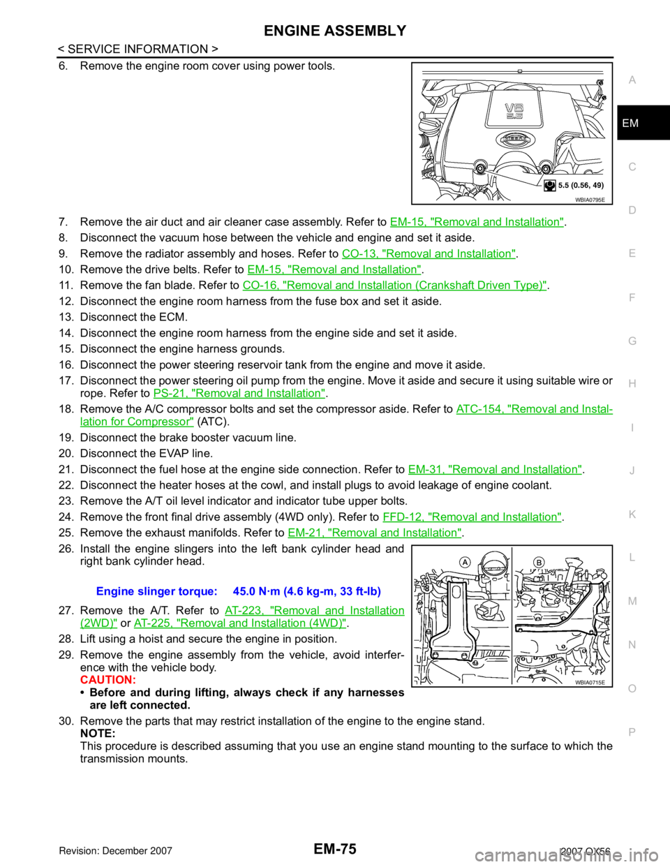
6. Remove the engine room cover using power tools.
7. Remove the air duct and air cleaner case assembly. Refer to EM-15, "
Removal and Installation".
8. Disconnect the vacuum hose between the vehicle and engine and set it aside.
9. Remove the radiator assembly and hoses. Refer to CO-13, "
Removal and Installation".
10. Remove the drive belts. Refer to EM-15, "
Removal and Installation".
11. Remove the fan blade. Refer to CO-16, "
Removal and Installation (Crankshaft Driven Type)".
12. Disconnect the engine room harness from the fuse box and set it aside.
13. Disconnect the ECM.
14. Disconnect the engine room harness from the engine side and set it aside.
15. Disconnect the engine harness grounds.
16. Disconnect the power steering reservoir tank from the engine and move it aside.
17. Disconnect the power steering oil pump from the engine. Move it aside and secure it using suitable wire or
rope. Refer to PS-21, "
Removal and Installation".
18. Remove the A/C compressor bolts and set the compressor aside. Refer to ATC-154, "
Removal and Instal-
lation for Compressor" (ATC).
19. Disconnect the brake booster vacuum line.
20. Disconnect the EVAP line.
21. Disconnect the fuel hose at the engine side connection. Refer to EM-31, "
Removal and Installation".
22. Disconnect the heater hoses at the cowl, and install plugs to avoid leakage of engine coolant.
23. Remove the A/T oil level indicator and indicator tube upper bolts.
24. Remove the front final drive assembly (4WD only). Refer to FFD-12, "
Removal and Installation".
25. Remove the exhaust manifolds. Refer to EM-21, "
Removal and Installation".
26. Install the engine slingers into the left bank cylinder head and
right bank cylinder head.
27. Remove the A/T. Refer to AT-223, "
Removal and Installation
(2WD)" or AT-225, "Removal and Installation (4WD)".
28. Lift using a hoist and secure the engine in position.
29. Remove the engine assembly from the vehicle, avoid interfer-
ence with the vehicle body.
CAUTION:
• Before and during lifting, always check if any harnesses
are left connected.
30. Remove the parts that may restrict installation of the engine to the engine stand.
NOTE:
This procedure is described assuming that you use an engine stand mounting to the surface to which the
transmission mounts.
WBIA0795E
Engine slinger torque: 45.0 N·m (4.6 kg-m, 33 ft-lb)
WBIA0715E
Page 1849 of 3061
CYLINDER BLOCK
EM-79
< SERVICE INFORMATION >
C
D
E
F
G
H
I
J
K
L
MA
EM
N
P O
DISASSEMBLY
NOTE:
Explained here is how to disassemble with engine stand supporting transmission surface. When using differ-
ent type of engine stand, some steps may be different.
1. Remove engine assembly and mount to engine stand. Refer to EM-74, "
Removal and Installation".
CAUTION:
Before removing the hanging chains, make sure engine stand is stable and there is no risk of over-
turning.
2. Drain engine oil. Refer to LU-9, "
Changing Engine Oil".
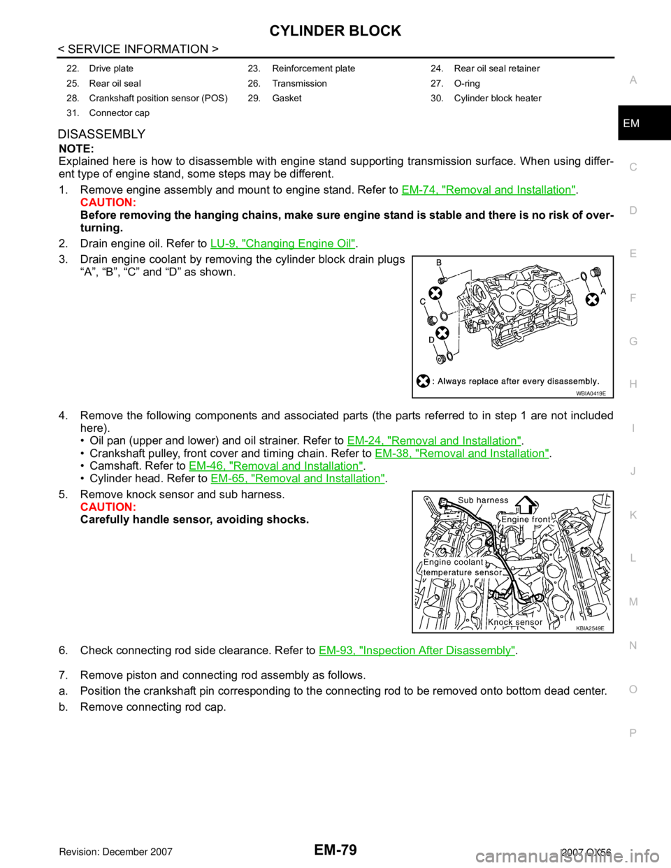
3. Drain engine coolant by removing the cylinder block drain plugs
“A”, “B”, “C” and “D” as shown.
4. Remove the following components and associated parts (the parts referred to in step 1 are not included
here).
• Oil pan (upper and lower) and oil strainer. Refer to EM-24, "
Removal and Installation".
• Crankshaft pulley, front cover and timing chain. Refer to EM-38, "
Removal and Installation".
• Camshaft. Refer to EM-46, "
Removal and Installation".
• Cylinder head. Refer to EM-65, "
Removal and Installation".
5. Remove knock sensor and sub harness.
CAUTION:
Carefully handle sensor, avoiding shocks.
6. Check connecting rod side clearance. Refer to EM-93, "
Inspection After Disassembly".
7. Remove piston and connecting rod assembly as follows.
a. Position the crankshaft pin corresponding to the connecting rod to be removed onto bottom dead center.
b. Remove connecting rod cap.
22. Drive plate 23. Reinforcement plate 24. Rear oil seal retainer
25. Rear oil seal 26. Transmission 27. O-ring
28. Crankshaft position sensor (POS) 29. Gasket 30. Cylinder block heater
31. Connector cap
WBIA0419E
KBIA2549E
Page 1852 of 3061
EM-82
< SERVICE INFORMATION >
CYLINDER BLOCK
ASSEMBLY
1. Fully air-blow the coolant and oil passages in the cylinder block, cylinder bore, and crankcase to remove
any foreign material.
CAUTION:
Use goggles to protect your eyes.
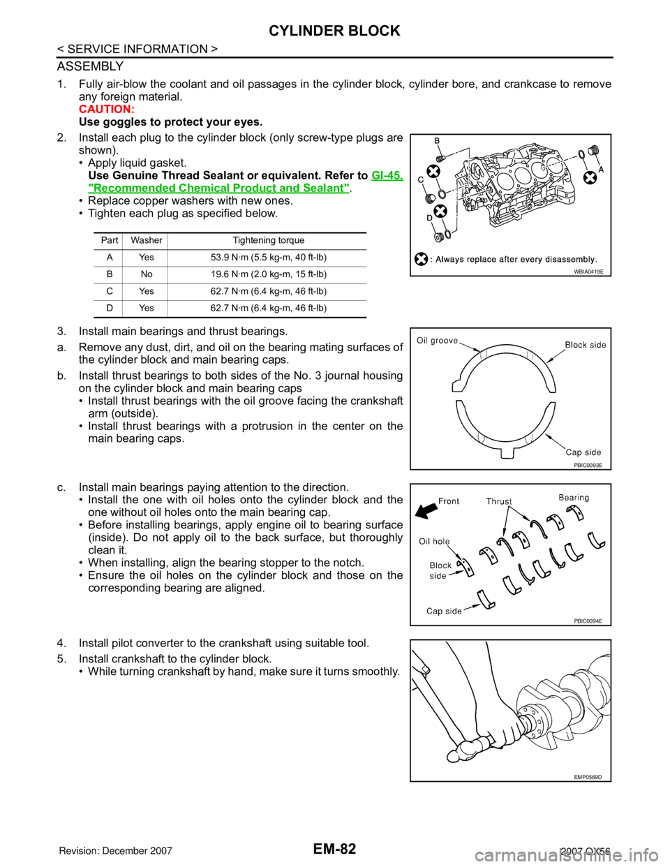
2. Install each plug to the cylinder block (only screw-type plugs are
shown).
• Apply liquid gasket.
Use Genuine Thread Sealant or equivalent. Refer to GI-45,
"Recommended Chemical Product and Sealant".
• Replace copper washers with new ones.
• Tighten each plug as specified below.
3. Install main bearings and thrust bearings.
a. Remove any dust, dirt, and oil on the bearing mating surfaces of
the cylinder block and main bearing caps.
b. Install thrust bearings to both sides of the No. 3 journal housing
on the cylinder block and main bearing caps
• Install thrust bearings with the oil groove facing the crankshaft
arm (outside).
• Install thrust bearings with a protrusion in the center on the
main bearing caps.
c. Install main bearings paying attention to the direction.
• Install the one with oil holes onto the cylinder block and the
one without oil holes onto the main bearing cap.
• Before installing bearings, apply engine oil to bearing surface
(inside). Do not apply oil to the back surface, but thoroughly
clean it.
• When installing, align the bearing stopper to the notch.
• Ensure the oil holes on the cylinder block and those on the
corresponding bearing are aligned.
4. Install pilot converter to the crankshaft using suitable tool.
5. Install crankshaft to the cylinder block.
• While turning crankshaft by hand, make sure it turns smoothly.
Part Washer Tightening torque
A Yes 53.9 N·m (5.5 kg-m, 40 ft-lb)
B No 19.6 N·m (2.0 kg-m, 15 ft-lb)
C Yes 62.7 N·m (6.4 kg-m, 46 ft-lb)
D Yes 62.7 N·m (6.4 kg-m, 46 ft-lb)
WBIA0419E
PBIC0093E
PBIC0094E
EMP0569D
Page 1930 of 3061
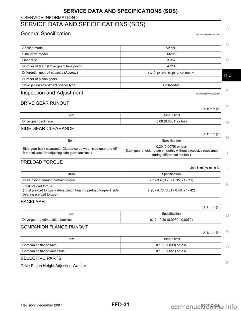
SERVICE DATA AND SPECIFICATIONS (SDS)
FFD-31
< SERVICE INFORMATION >
C
E
F
G
H
I
J
K
L
MA
B
FFD
N
O
P
SERVICE DATA AND SPECIFICATIONS (SDS)
General SpecificationINFOID:0000000003532595
Inspection and AdjustmentINFOID:0000000003532596
DRIVE GEAR RUNOUT
Unit: mm (in)
SIDE GEAR CLEARANCE
Unit: mm (in)
PRELOAD TORQUE
Unit: N·m (kg-m, in-lb)
BACKLASH
Unit: mm (in)
COMPANION FLANGE RUNOUT
Unit: mm (in)
SELECTIVE PARTS
Drive Pinion Height Adjusting Washer
Applied modelVK56E
Final drive modelM205
Gear ratio3.357
Number of teeth (Drive gear/Drive pinion) 47/14
Differential gear oil capacity (Approx.)
1.6 (3 3/8 US pt, 2 7/8 Imp pt)
Number of pinion gears2
Drive pinion adjustment spacer type Collapsible
Item Runout limit
Drive gear back face 0.08 (0.0031) or less
Item Specification
Side gear back clearance (Clearance between side gear and dif-
ferential case for adjusting side gear backlash)0.20 (0.0079) or less
(Each gear should rotate smoothly without excessive resistance
during differential motion.)
Item Specification
Drive pinion bearing preload torque 2.3 - 3.4 (0.23 - 0.35, 21 - 31)
Total preload torque
(Total preload torque = drive pinion bearing preload torque + side
bearing preload torque).2.98 - 4.76 (0.31 - 0.48, 27 - 42)
Item Specification
Drive gear to drive pinion backlash 0.12 - 0.20 (0.0050 - 0.0079)
Item Runout limit
Companion flange face 0.10 (0.0039) or less
Companion flange inner side 0.13 (0.0051) or less
Page 1952 of 3061
FSU-6
< SERVICE INFORMATION >
ON-VEHICLE SERVICE
ON-VEHICLE SERVICE
Front Suspension PartsINFOID:0000000003532636
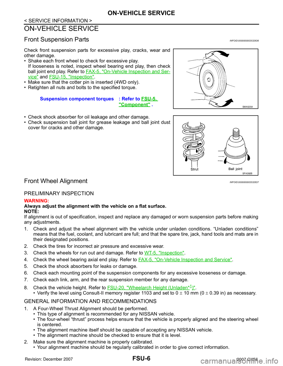
Check front suspension parts for excessive play, cracks, wear and
other damage.
• Shake each front wheel to check for excessive play.
If looseness is noted, inspect wheel bearing end play, then check
ball joint end play. Refer to FA X - 5 , "
On-Vehicle Inspection and Ser-
vice" and FSU-15, "Inspection".
• Make sure that the cotter pin is inserted (4WD only).
• Retighten all nuts and bolts to the specified torque.
• Check shock absorber for oil leakage and other damage.
• Check suspension ball joint for grease leakage and ball joint dust
cover for cracks and other damage.
Front Wheel AlignmentINFOID:0000000003532637
PRELIMINARY INSPECTION
WARNING:
Always adjust the alignment with the vehicle on a flat surface.
NOTE:
If alignment is out of specification, inspect and replace any damaged or worn suspension parts before making
any adjustments.
1. Check and adjust the wheel alignment with the vehicle under unladen conditions. “Unladen conditions”
means that the fuel, coolant, and lubricant are full; and that the spare tire, jack, hand tools and mats are in
their designated positions.
2. Check the tires for incorrect air pressure and excessive wear.
3. Check the wheels for run out and damage. Refer to WT-5, "
Inspection".
4. Check the wheel bearing axial end play. Refer to FA X - 5 , "
On-Vehicle Inspection and Service".
5. Check the shock absorbers for leaks or damage.
6. Check each mounting point of the suspension components for any excessive looseness or damage.
7. Check each link, arm, and the rear suspension member for any damage.
8. Check the vehicle height. Refer to FSU-20, "
Wheelarch Height (Unladen*1)".
• Verify the level using Consult-II memory register 1103 and set to 0 ± 10 mm (0 ± 0.39 in) as necessary.
GENERAL INFORMATION AND RECOMMENDATIONS
1. A Four-Wheel Thrust Alignment should be performed.
• This type of alignment is recommended for any NISSAN vehicle.
• The four-wheel “thrust” process helps ensure that the vehicle is properly aligned and the steering wheel
is centered.
• The alignment machine itself should be capable of accepting any NISSAN vehicle.
• The alignment machine should be checked to ensure that it is level.
2. Make sure the alignment machine is properly calibrated.
• Your alignment machine should be regularly calibrated in order to give correct information.Suspension component torques : Refer to FSU-5,
"Component" . SMA525A
SFA392B
Page 1965 of 3061
SERVICE DATA AND SPECIFICATIONS (SDS)
FSU-19
< SERVICE INFORMATION >
C
D
F
G
H
I
J
K
L
MA
B
FSU
N
O
P
SERVICE DATA AND SPECIFICATIONS (SDS)
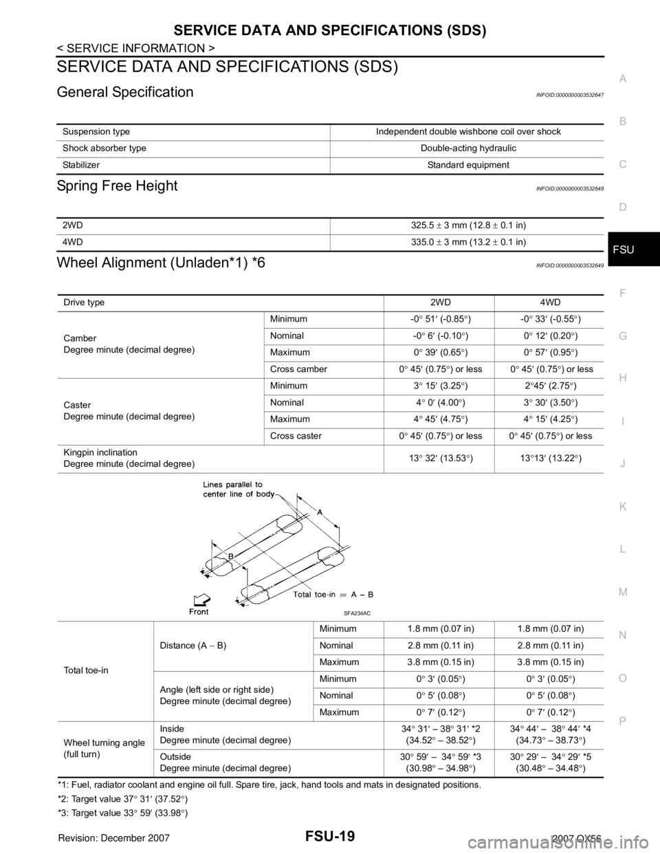
General SpecificationINFOID:0000000003532647
Spring Free HeightINFOID:0000000003532648
Wheel Alignment (Unladen*1) *6INFOID:0000000003532649
*1: Fuel, radiator coolant and engine oil full. Spare tire, jack, hand tools and mats in designated positions.
*2: Target value 37° 31′ (37.52°)
*3: Target value 33° 59′ (33.98°) Suspension type Independent double wishbone coil over shock
Shock absorber type Double-acting hydraulic
StabilizerStandard equipment
2WD325.5 ± 3 mm (12.8 ± 0.1 in)
4WD335.0 ± 3 mm (13.2 ± 0.1 in)
Drive type2WD 4WD
Camber
Degree minute (decimal degree)Minimum -0° 51′ (-0.85°)-0° 33′ (-0.55°)
Nominal -0° 6′ (-0.10°)0° 12′ (0.20°)
Maximum 0° 39′ (0.65°)0° 57′ (0.95°)
Cross camber 0° 45′ (0.75°) or less 0° 45′ (0.75°) or less
Caster
Degree minute (decimal degree)Minimum 3° 15′ (3.25°)2°45′ (2.75°)
Nominal 4° 0′ (4.00°)3° 30′ (3.50°)
Maximum 4° 45′ (4.75°)4° 15′ (4.25°)
Cross caster 0° 45′
(0.75°) or less 0° 45′ (0.75°) or less
Kingpin inclination
Degree minute (decimal degree)13° 32′ (13.53°)13°13′ (13.22°)
Total toe-inDistance (A − B)Minimum 1.8 mm (0.07 in) 1.8 mm (0.07 in)
Nominal 2.8 mm (0.11 in) 2.8 mm (0.11 in)
Maximum 3.8 mm (0.15 in) 3.8 mm (0.15 in)
Angle (left side or right side)
Degree minute (decimal degree)Minimum 0° 3′ (0.05°)0° 3′ (0.05°)
Nominal 0° 5′ (0.08°)0° 5′ (0.08°)
Maximum 0° 7′ (0.12°)0° 7′ (0.12°)
Wheel turning angle
(full turn)Inside
Degree minute (decimal degree)34° 31′ – 38° 31′ *2
(34.52° – 38.52°)34° 44′ – 38° 44′ *4
(34.73° – 38.73
°)
Outside
Degree minute (decimal degree)30° 59′ – 34° 59′ *3
(30.98° – 34.98°)30° 29′ – 34° 29′ *5
(30.48° – 34.48°)
SFA234AC