Page 2490 of 3061

SERVICE DATA AND SPECIFICATIONS (SDS)
PR-13
< SERVICE INFORMATION >
C
E
F
G
H
I
J
K
L
MA
B
PR
N
O
P
SERVICE DATA AND SPECIFICATIONS (SDS)
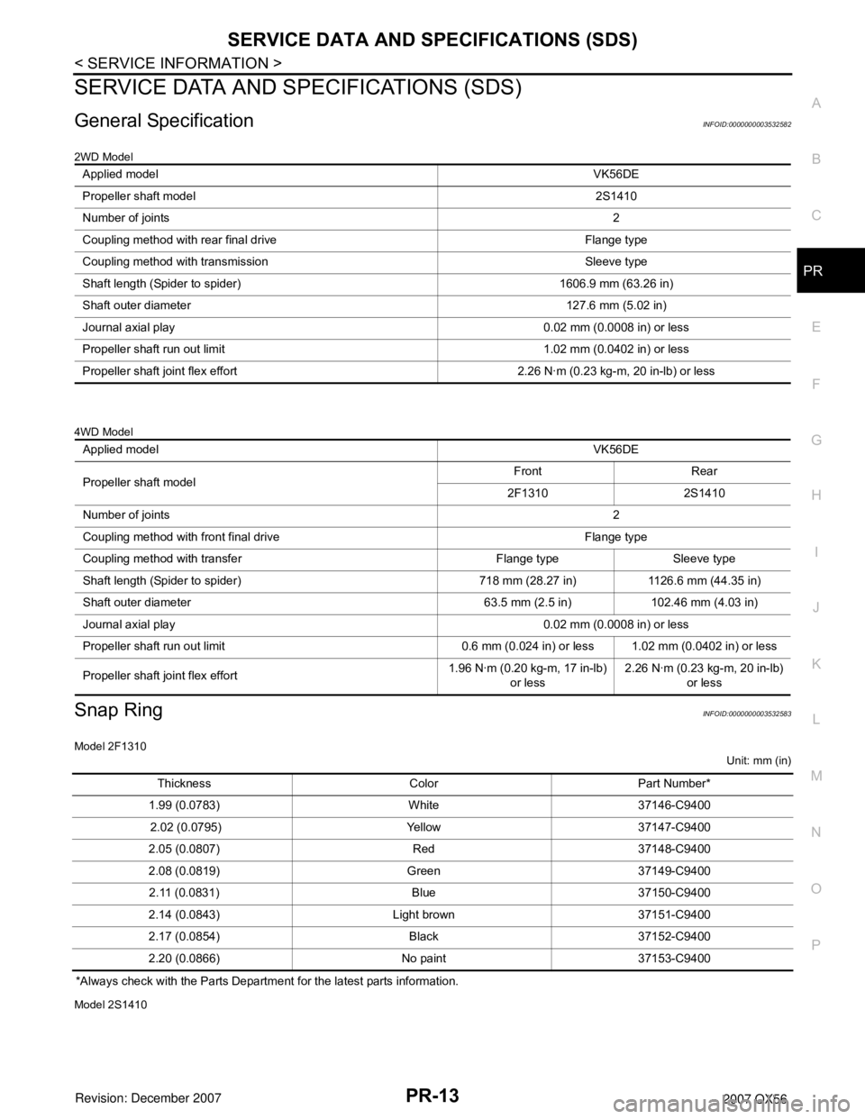
General SpecificationINFOID:0000000003532582
2WD Model
4WD Model
Snap RingINFOID:0000000003532583
Model 2F1310
Unit: mm (in)
*Always check with the Parts Department for the latest parts information.
Model 2S1410
Applied modelVK56DE
Propeller shaft model2S1410
Number of joints2
Coupling method with rear final drive Flange type
Coupling method with transmission Sleeve type
Shaft length (Spider to spider) 1606.9 mm (63.26 in)
Shaft outer diameter 127.6 mm (5.02 in)
Journal axial play 0.02 mm (0.0008 in) or less
Propeller shaft run out limit 1.02 mm (0.0402 in) or less
Propeller shaft joint flex effort 2.26 N·m (0.23 kg-m, 20 in-lb) or less
Applied modelVK56DE
Propeller shaft modelFront Rear
2F1310 2S1410
Number of joints2
Coupling method with front final drive Flange type
Coupling method with transfer Flange type Sleeve type
Shaft length (Spider to spider) 718 mm (28.27 in) 1126.6 mm (44.35 in)
Shaft outer diameter 63.5 mm (2.5 in) 102.46 mm (4.03 in)
Journal axial play 0.02 mm (0.0008 in) or less
Propeller shaft run out limit 0.6 mm (0.024 in) or less 1.02 mm (0.0402 in) or less
Propeller shaft joint flex effort1.96 N·m (0.20 kg-m, 17 in-lb)
or less2.26 N·m (0.23 kg-m, 20 in-lb)
or less
Thickness Color Part Number*
1.99 (0.0783) White 37146-C9400
2.02 (0.0795) Yellow 37147-C9400
2.05 (0.0807) Red 37148-C9400
2.08 (0.0819) Green 37149-C9400
2.11 (0.0831) Blue 37150-C9400
2.14 (0.0843) Light brown 37151-C9400
2.17 (0.0854) Black 37152-C9400
2.20 (0.0866) No paint 37153-C9400
Page 2502 of 3061

STEERING COLUMN
PS-11
< SERVICE INFORMATION >
C
D
E
F
H
I
J
K
L
MA
B
PS
N
O
P
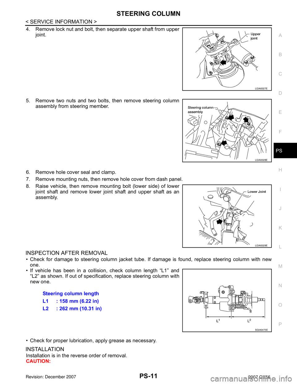
4. Remove lock nut and bolt, then separate upper shaft from upper
joint.
5. Remove two nuts and two bolts, then remove steering column
assembly from steering member.
6. Remove hole cover seal and clamp.
7. Remove mounting nuts, then remove hole cover from dash panel.
8. Raise vehicle, then remove mounting bolt (lower side) of lower
joint shaft and remove lower joint shaft and upper shaft as an
assembly.
INSPECTION AFTER REMOVAL
• Check for damage to steering column jacket tube. If damage is found, replace steering column with new
one.
• If vehicle has been in a collision, check column length “L1” and
“L2” as shown. If out of specification, replace steering column with
new one.
• Check for proper lubrication, apply grease as necessary.
INSTALLATION
Installation is in the reverse order of removal.
CAUTION:
LGIA0027E
LGIA0028E
LGIA0029E
Steering column length
L1 : 158 mm (6.22 in)
L2 : 262 mm (10.31 in)
SGIA0475E
Page 2505 of 3061
PS-14
< SERVICE INFORMATION >
STEERING COLUMN
3. If the vehicle has been involved in a collision, or if noise and rat-
tles are heard during a turn, check the length "L" of the column.
If out of specification, replace the steering column as an assem-
bly.
4. Check for proper lubrication, apply grease as necessary.
5. Check for wear around the seal edges, replace the steering col-
umn as an assembly as necessary.
6. Check for corrosion or pitting around the seal sliding area.Steering column length "L" : 610 mm (24.02 in)
WGIA0080E
Page 2511 of 3061
PS-20
< SERVICE INFORMATION >
POWER STEERING GEAR AND LINKAGE
5. Crimp the large-diameter boot clamps, using Tool.
6. Install the cylinder tubes to the gear housing assembly.
7. Install the lock nuts and outer sockets to the inner sockets.
8. Thread the outer sockets onto the inner sockets to the specified
length "L", then tighten the lock nuts to the specification. Refer to
PS-15, "
Removal and Installation". Reconfirm that the tie-rod
length "L" is within specification.Tool number : KV40107300 ( — )
RAC1133D
Maximum inner socket
length "L": 115.2 mm (4.54 in)
SGIA0167E
Page 2516 of 3061
SERVICE DATA AND SPECIFICATIONS (SDS)
PS-25
< SERVICE INFORMATION >
C
D
E
F
H
I
J
K
L
MA
B
PS
N
O
P
SERVICE DATA AND SPECIFICATIONS (SDS)
Steering WheelINFOID:0000000003532835
Steering ColumnINFOID:0000000003532836
Inspection After Assembly
Unit: mm (in)
Inspection After Removal
Unit: mm (in)
Inspection After Installation
End play of the axial direction for steering wheel 0 mm (0 in)
Steering wheel play on the outer circumference 0 − 35 mm (0 − 1.38 in)
Steering wheel turning force 39 N (4 kg-f, 9 lb-f) or less
Steering column length “L”610 (24.02)
WGIA0080E
Steering column length “L2”262 (10.31)
Steering column length “L1” 158 (6.22)
Range “A”61.3 mm (2.41 in)
SGIA0475E
WGIA0083E
Page 2517 of 3061
PS-26
< SERVICE INFORMATION >
SERVICE DATA AND SPECIFICATIONS (SDS)
Steering Outer Socket and Inner Socket
INFOID:0000000003532837
Unit: mm (in)
Steering GearINFOID:0000000003532838
Tie-rod ball joint outer socketSwinging torque 0.3 − 2.9 N·m (0.03 − 0.29 kg-m, 3 − 25 in-lb)
Measurement on spring balance
• Measuring point: cotter pin hole of stud4.84 − 46.7 N (0.50 − 4.7 kg, 4 − 34 lb)
Rotating torque 0.3 − 2.9 N·m (0.03 − 0.29 kg-m, 3 − 25 in-lb)
Axial end play 0.5 mm (0.020 in) or less
Tie-rod ball joint inner socketSwinging torque 1.0 − 7.8 N·m (0.11 − 0.79 kg-m, 9 − 69 in-lb)
Measurement on spring balance
• Measuring point: "L" mark see above,
"L"=83.2 mm (3.276 in).12.1 − 93.7 N (1.3 − 9.5 kg, 9 − 69 lb)
Axial end play 0.2 mm (0.08 in) or less
SGIA0358E
Inner socket length “L” 115.2 (4.54)
SGIA0167E
Steering gear modelPR26AM
Rack neutral position, dimension “L” (rack stroke) 85.5 mm (3.36 in)
STC0034D
Page 2529 of 3061

REAR DRIVE SHAFT
RAX-11
< SERVICE INFORMATION >
C
E
F
G
H
I
J
K
L
MA
B
RAX
N
O
P
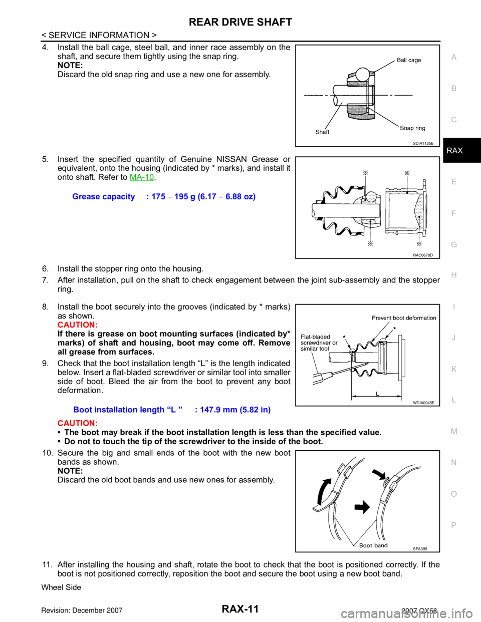
4. Install the ball cage, steel ball, and inner race assembly on the
shaft, and secure them tightly using the snap ring.
NOTE:
Discard the old snap ring and use a new one for assembly.
5. Insert the specified quantity of Genuine NISSAN Grease or
equivalent, onto the housing (indicated by * marks), and install it
onto shaft. Refer to MA-10
.
6. Install the stopper ring onto the housing.
7. After installation, pull on the shaft to check engagement between the joint sub-assembly and the stopper
ring.
8. Install the boot securely into the grooves (indicated by * marks)
as shown.
CAUTION:
If there is grease on boot mounting surfaces (indicated by*
marks) of shaft and housing, boot may come off. Remove
all grease from surfaces.
9. Check that the boot installation length “L” is the length indicated
below. Insert a flat-bladed screwdriver or similar tool into smaller
side of boot. Bleed the air from the boot to prevent any boot
deformation.
CAUTION:
• The boot may break if the boot installation length is less than the specified value.
• Do not to touch the tip of the screwdriver to the inside of the boot.
10. Secure the big and small ends of the boot with the new boot
bands as shown.
NOTE:
Discard the old boot bands and use new ones for assembly.
11. After installing the housing and shaft, rotate the boot to check that the boot is positioned correctly. If the
boot is not positioned correctly, reposition the boot and secure the boot using a new boot band.
Wheel Side
SDIA1125E
Grease capacity : 175 − 195 g (6.17 − 6.88 oz)
RAC0678D
Boot installation length “L ” : 147.9 mm (5.82 in)
WDIA0045E
SFA395
Page 2530 of 3061

RAX-12
< SERVICE INFORMATION >
REAR DRIVE SHAFT
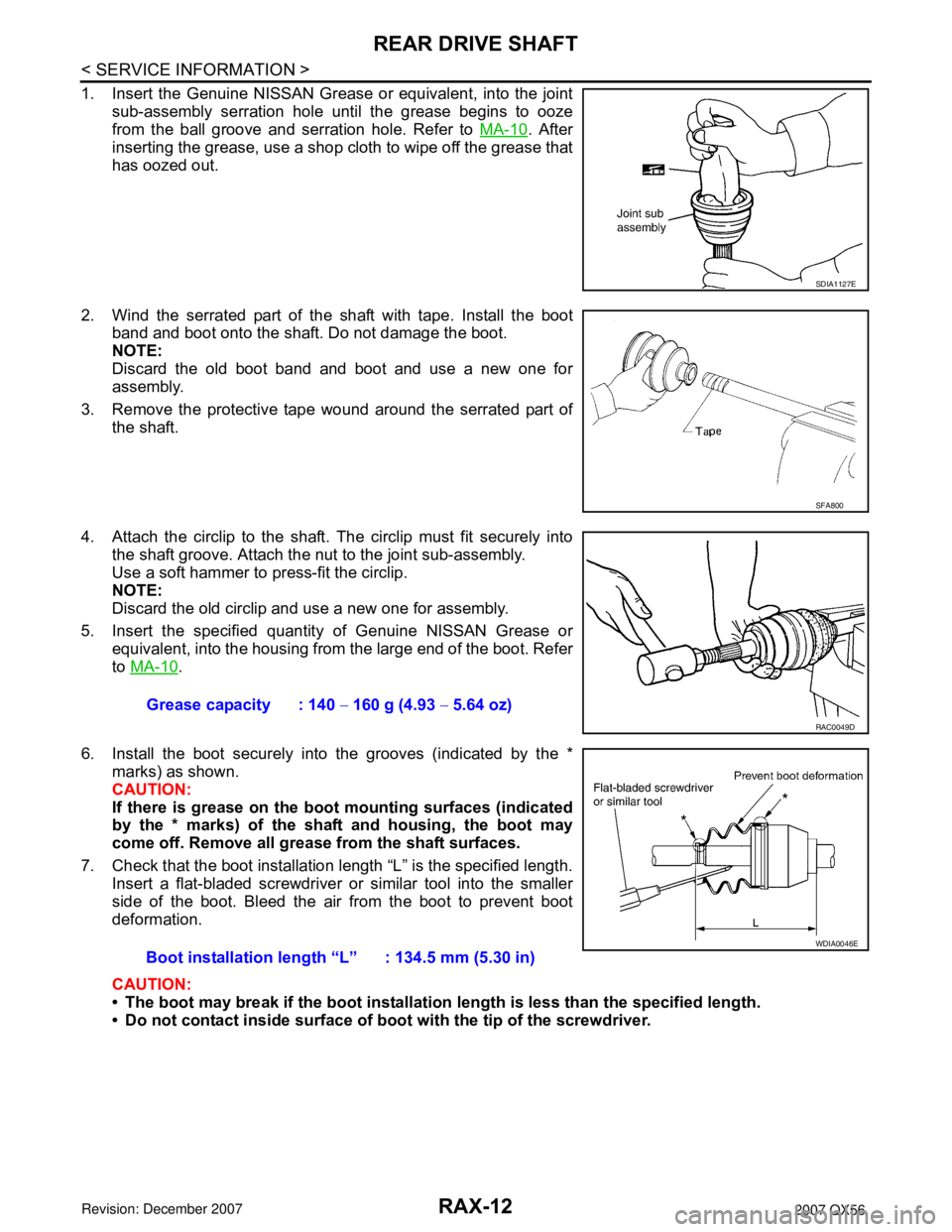
1. Insert the Genuine NISSAN Grease or equivalent, into the joint
sub-assembly serration hole until the grease begins to ooze
from the ball groove and serration hole. Refer to MA-10
. After
inserting the grease, use a shop cloth to wipe off the grease that
has oozed out.
2. Wind the serrated part of the shaft with tape. Install the boot
band and boot onto the shaft. Do not damage the boot.
NOTE:
Discard the old boot band and boot and use a new one for
assembly.
3. Remove the protective tape wound around the serrated part of
the shaft.
4. Attach the circlip to the shaft. The circlip must fit securely into
the shaft groove. Attach the nut to the joint sub-assembly.
Use a soft hammer to press-fit the circlip.
NOTE:
Discard the old circlip and use a new one for assembly.
5. Insert the specified quantity of Genuine NISSAN Grease or
equivalent, into the housing from the large end of the boot. Refer
to MA-10
.
6. Install the boot securely into the grooves (indicated by the *
marks) as shown.
CAUTION:
If there is grease on the boot mounting surfaces (indicated
by the * marks) of the shaft and housing, the boot may
come off. Remove all grease from the shaft surfaces.
7. Check that the boot installation length “L” is the specified length.
Insert a flat-bladed screwdriver or similar tool into the smaller
side of the boot. Bleed the air from the boot to prevent boot
deformation.
CAUTION:
• The boot may break if the boot installation length is less than the specified length.
• Do not contact inside surface of boot with the tip of the screwdriver.
SDIA1127E
SFA800
Grease capacity : 140 − 160 g (4.93 − 5.64 oz)
RAC0049D
Boot installation length “L” : 134.5 mm (5.30 in)
WDIA0046E