2007 INFINITI QX56 length
[x] Cancel search: lengthPage 927 of 3061
SERVICE DATA AND SPECIFICATIONS (SDS)
BR-29
< SERVICE INFORMATION >
C
D
E
G
H
I
J
K
L
MA
B
BR
N
O
P
SERVICE DATA AND SPECIFICATIONS (SDS)
General SpecificationINFOID:0000000003532748
Unit: mm (in)
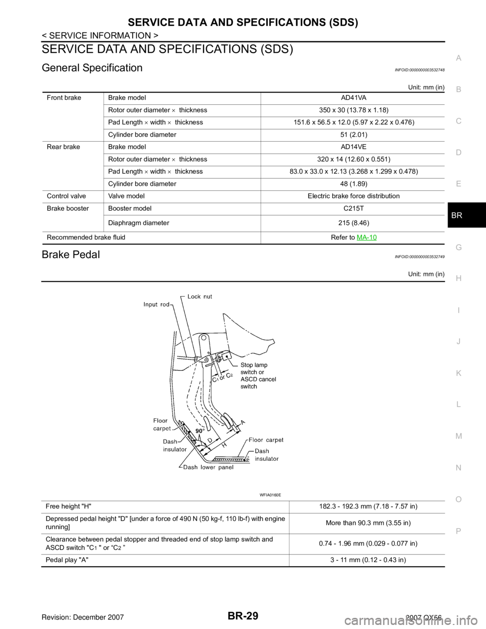
Brake PedalINFOID:0000000003532749
Unit: mm (in)
Front brake Brake model AD41VA
Rotor outer diameter × thickness 350 x 30 (13.78 x 1.18)
Pad Length × width × thickness 151.6 x 56.5 x 12.0 (5.97 x 2.22 x 0.476)
Cylinder bore diameter 51 (2.01)
Rear brake Brake model AD14VE
Rotor outer diameter × thickness 320 x 14 (12.60 x 0.551)
Pad Length × width × thickness 83.0 x 33.0 x 12.13 (3.268 x 1.299 x 0.478)
Cylinder bore diameter 48 (1.89)
Control valve Valve model Electric brake force distribution
Brake booster Booster model C215T
Diaphragm diameter 215 (8.46)
Recommended brake fluid Refer to MA-10
Free height "H"182.3 - 192.3 mm (7.18 - 7.57 in)
Depressed pedal height "D" [under a force of 490 N (50 kg-f, 110 lb-f) with engine
running]More than 90.3 mm (3.55 in)
Clearance between pedal stopper and threaded end of stop lamp switch and
ASCD switch "C
1 " or “C2 ”0.74 - 1.96 mm (0.029 - 0.077 in)
Pedal play "A"3 - 11 mm (0.12 - 0.43 in)
WFIA0160E
Page 1108 of 3061
ENGINE CONTROL SYSTEM
EC-25
< SERVICE INFORMATION >
C
D
E
F
G
H
I
J
K
L
MA
EC
N
P O
*1: This sensor is not used to control the engine system. This is used only for the on board diagnosis.
*2: This signal is sent to the ECM through CAN communication line.
*3: ECM determines the start signal status by the signals of engine speed and battery voltage.
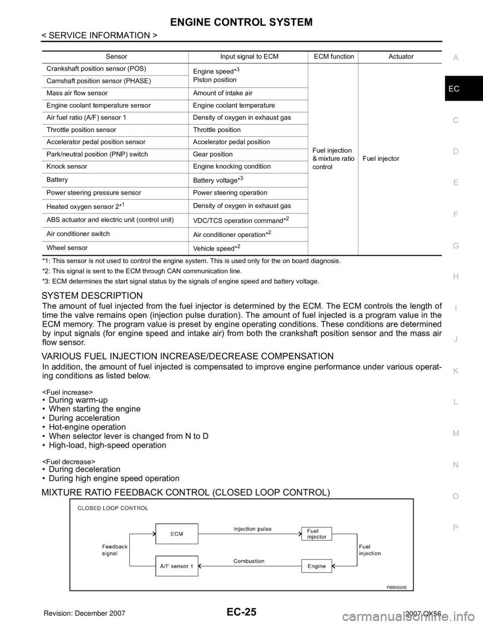
SYSTEM DESCRIPTION
The amount of fuel injected from the fuel injector is determined by the ECM. The ECM controls the length of
time the valve remains open (injection pulse duration). The amount of fuel injected is a program value in the
ECM memory. The program value is preset by engine operating conditions. These conditions are determined
by input signals (for engine speed and intake air) from both the crankshaft position sensor and the mass air
flow sensor.
VARIOUS FUEL INJECTION INCREASE/DECREASE COMPENSATION
In addition, the amount of fuel injected is compensated to improve engine performance under various operat-
ing conditions as listed below.
• When starting the engine
• During acceleration
• Hot-engine operation
• When selector lever is changed from N to D
• High-load, high-speed operation
• During deceleration
• During high engine speed operation
MIXTURE RATIO FEEDBACK CONTROL (CLOSED LOOP CONTROL)
Sensor Input signal to ECM ECM function Actuator
Crankshaft position sensor (POS)
Engine speed*
3
Piston position
Fuel injection
& mixture ratio
controlFuel injector Camshaft position sensor (PHASE)
Mass air flow sensor Amount of intake air
Engine coolant temperature sensor Engine coolant temperature
Air fuel ratio (A/F) sensor 1 Density of oxygen in exhaust gas
Throttle position sensor Throttle position
Accelerator pedal position sensor Accelerator pedal position
Park/neutral position (PNP) switch Gear position
Knock sensor Engine knocking condition
Battery
Battery voltage*
3
Power steering pressure sensor Power steering operation
Heated oxygen sensor 2*
1Density of oxygen in exhaust gas
ABS actuator and electric unit (control unit)
VDC/TCS operation command*
2
Air conditioner switch
Air conditioner operation*2
Wheel sensor
Vehicle speed*2
PBIB3020E
Page 1148 of 3061
ON BOARD DIAGNOSTIC (OBD) SYSTEM
EC-65
< SERVICE INFORMATION >
C
D
E
F
G
H
I
J
K
L
MA
EC
N
P O
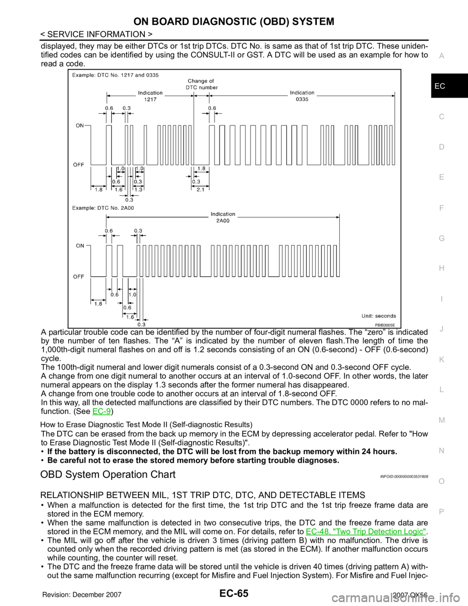
displayed, they may be either DTCs or 1st trip DTCs. DTC No. is same as that of 1st trip DTC. These uniden-
tified codes can be identified by using the CONSULT-II or GST. A DTC will be used as an example for how to
read a code.
A particular trouble code can be identified by the number of four-digit numeral flashes. The “zero” is indicated
by the number of ten flashes. The “A” is indicated by the number of eleven flash.The length of time the
1,000th-digit numeral flashes on and off is 1.2 seconds consisting of an ON (0.6-second) - OFF (0.6-second)
cycle.
The 100th-digit numeral and lower digit numerals consist of a 0.3-second ON and 0.3-second OFF cycle.
A change from one digit numeral to another occurs at an interval of 1.0-second OFF. In other words, the later
numeral appears on the display 1.3 seconds after the former numeral has disappeared.
A change from one trouble code to another occurs at an interval of 1.8-second OFF.
In this way, all the detected malfunctions are classified by their DTC numbers. The DTC 0000 refers to no mal-
function. (See EC-9
)
How to Erase Diagnostic Test Mode II (Self-diagnostic Results)
The DTC can be erased from the back up memory in the ECM by depressing accelerator pedal. Refer to "How
to Erase Diagnostic Test Mode II (Self-diagnostic Results)".
•If the battery is disconnected, the DTC will be lost from the backup memory within 24 hours.
•Be careful not to erase the stored memory before starting trouble diagnoses.
OBD System Operation ChartINFOID:0000000003531608
RELATIONSHIP BETWEEN MIL, 1ST TRIP DTC, DTC, AND DETECTABLE ITEMS
• When a malfunction is detected for the first time, the 1st trip DTC and the 1st trip freeze frame data are
stored in the ECM memory.
• When the same malfunction is detected in two consecutive trips, the DTC and the freeze frame data are
stored in the ECM memory, and the MIL will come on. For details, refer to EC-48, "
Two Trip Detection Logic".
• The MIL will go off after the vehicle is driven 3 times (driving pattern B) with no malfunction. The drive is
counted only when the recorded driving pattern is met (as stored in the ECM). If another malfunction occurs
while counting, the counter will reset.
• The DTC and the freeze frame data will be stored until the vehicle is driven 40 times (driving pattern A) with-
out the same malfunction recurring (except for Misfire and Fuel Injection System). For Misfire and Fuel Injec-
PBIB3005E
Page 1691 of 3061
EC-608
< SERVICE INFORMATION >
FUEL INJECTOR
FUEL INJECTOR
Component DescriptionINFOID:0000000003532160
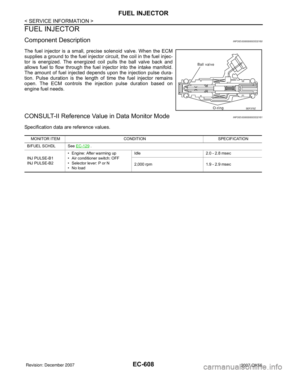
The fuel injector is a small, precise solenoid valve. When the ECM
supplies a ground to the fuel injector circuit, the coil in the fuel injec-
tor is energized. The energized coil pulls the ball valve back and
allows fuel to flow through the fuel injector into the intake manifold.
The amount of fuel injected depends upon the injection pulse dura-
tion. Pulse duration is the length of time the fuel injector remains
open. The ECM controls the injection pulse duration based on
engine fuel needs.
CONSULT-II Reference Value in Data Monitor ModeINFOID:0000000003532161
Specification data are reference values.
SEF375Z
MONITOR ITEM CONDITION SPECIFICATION
B/FUEL SCHDL See EC-129
.
INJ PULSE-B1
INJ PULSE-B2• Engine: After warming up
• Air conditioner switch: OFF
• Selector lever: P or N
•No loadIdle 2.0 - 2.8 msec
2,000 rpm 1.9 - 2.9 msec
Page 1806 of 3061
EM-36
< SERVICE INFORMATION >
ROCKER COVER
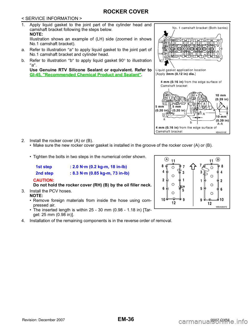
1. Apply liquid gasket to the joint part of the cylinder head andcamshaft bracket following the steps below.
NOTE:
Illustration shows an example of (LH) side (zoomed in shows
No.1 camshaft bracket).
a. Refer to illustration ″a ″ to apply liquid gasket to the joint part of
No.1 camshaft bracket and cylinder head.
b. Refer to illustration ″b ″ to apply liquid gasket 90 ° to illustration
″ a ″.
Use Genuine RTV Silicone Seal ant or equivalent. Refer to
GI-45, "
Recommended Chemical Product and Sealant".
2. Install the rocker cover (A) or (B). • Make sure the new rocker cover gasket is installed in the groove of the rocker cover (A) or (B).
• Tighten the bolts in two steps in the numerical order shown.
CAUTION:
Do not hold the rocker cover (RH) (B) by the oil filler neck.
3. Install the PCV hoses. NOTE:
• Remove foreign materials from inside the hose using com-
pressed air.
• The inserted length is within 25 - 30 mm (0.98 - 1.18 in) [Tar-
get: 25 mm (0.98 in)].
4. Installation of the remaining components is in the reverse order of removal.
KBIA2510E
1st step : 2.0 N·m (0.2 kg-m, 18 in-lb)
2nd step : 8.3 N·m (0.85 kg-m, 73 in-lb)
WBIA0697E
Page 1865 of 3061
CYLINDER BLOCK
EM-95
< SERVICE INFORMATION >
C
D
E
F
G
H
I
J
K
L
MA
EM
N
P O
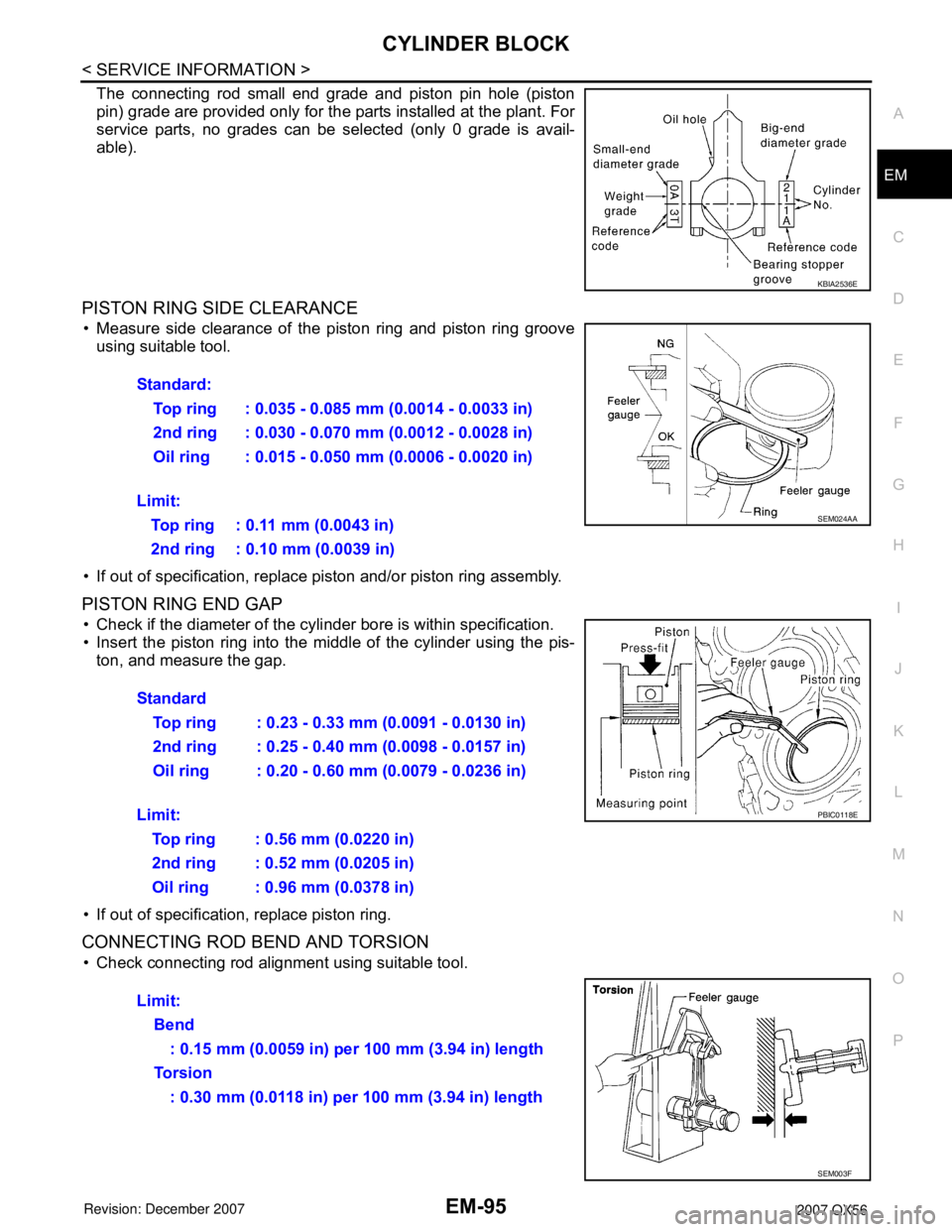
The connecting rod small end grade and piston pin hole (piston
pin) grade are provided only for the parts installed at the plant. For
service parts, no grades can be selected (only 0 grade is avail-
able).
PISTON RING SIDE CLEARANCE
• Measure side clearance of the piston ring and piston ring groove
using suitable tool.
• If out of specification, replace piston and/or piston ring assembly.
PISTON RING END GAP
• Check if the diameter of the cylinder bore is within specification.
• Insert the piston ring into the middle of the cylinder using the pis-
ton, and measure the gap.
• If out of specification, replace piston ring.
CONNECTING ROD BEND AND TORSION
• Check connecting rod alignment using suitable tool.
KBIA2536E
Standard:
Top ring : 0.035 - 0.085 mm (0.0014 - 0.0033 in)
2nd ring : 0.030 - 0.070 mm (0.0012 - 0.0028 in)
Oil ring : 0.015 - 0.050 mm (0.0006 - 0.0020 in)
Limit:
Top ring : 0.11 mm (0.0043 in)
2nd ring : 0.10 mm (0.0039 in)
SEM024AA
Standard
Top ring : 0.23 - 0.33 mm (0.0091 - 0.0130 in)
2nd ring : 0.25 - 0.40 mm (0.0098 - 0.0157 in)
Oil ring : 0.20 - 0.60 mm (0.0079 - 0.0236 in)
Limit:
Top ring : 0.56 mm (0.0220 in)
2nd ring : 0.52 mm (0.0205 in)
Oil ring : 0.96 mm (0.0378 in)
PBIC0118E
Limit:
Bend
: 0.15 mm (0.0059 in) per 100 mm (3.94 in) length
To r s i o n
: 0.30 mm (0.0118 in) per 100 mm (3.94 in) length
SEM003F
Page 1876 of 3061
EM-106
< SERVICE INFORMATION >
SERVICE DATA AND SPECIFICATIONS (SDS)
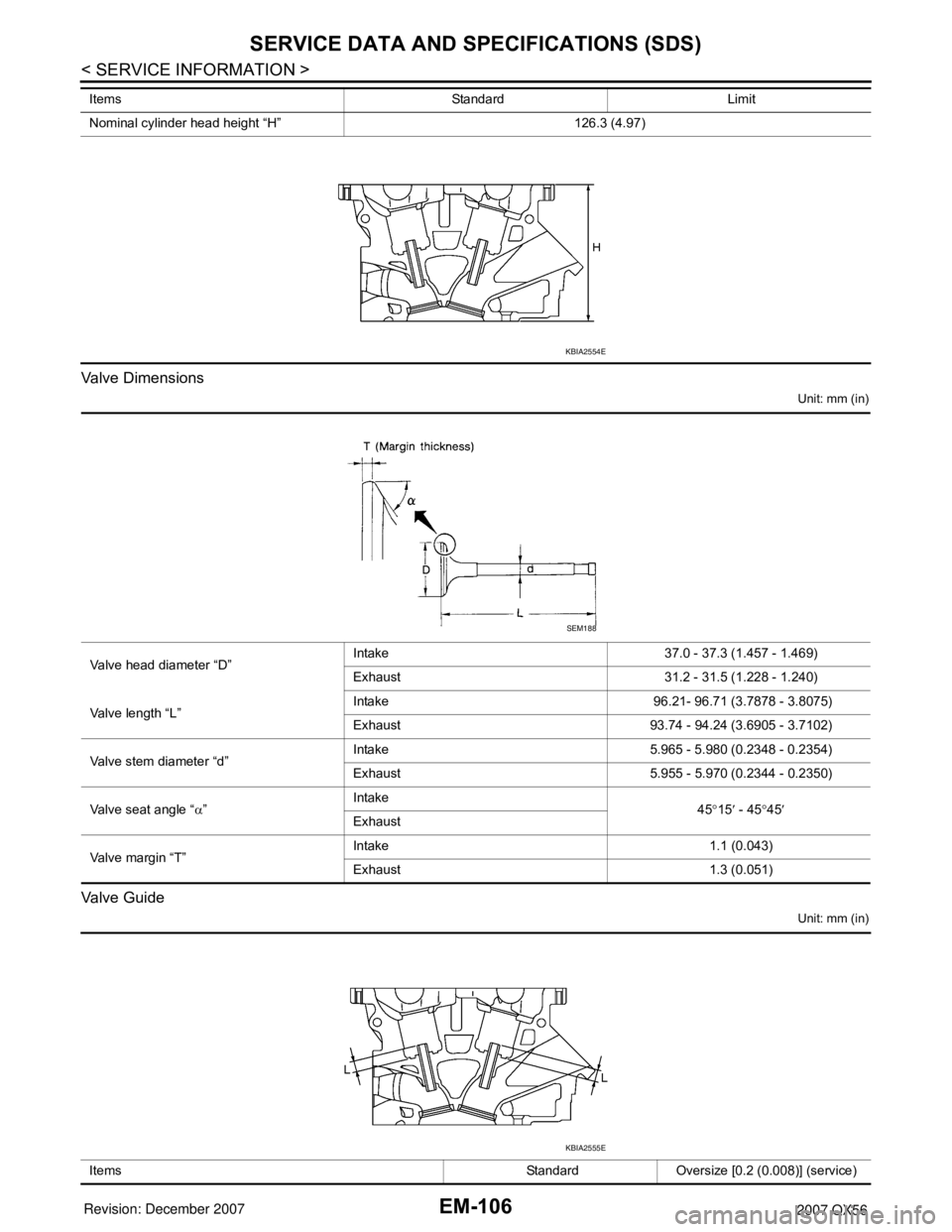
Valve Dimensions
Unit: mm (in)
Valve Guide
Unit: mm (in)
Nominal cylinder head height “H” 126.3 (4.97) Items Standard Limit
KBIA2554E
Valve head diameter “D”Intake 37.0 - 37.3 (1.457 - 1.469)
Exhaust 31.2 - 31.5 (1.228 - 1.240)
Valve length “L”Intake 96.21- 96.71 (3.7878 - 3.8075)
Exhaust 93.74 - 94.24 (3.6905 - 3.7102)
Valve stem diameter “d”Intake 5.965 - 5.980 (0.2348 - 0.2354)
Exhaust 5.955 - 5.970 (0.2344 - 0.2350)
Valve seat angle “α”Intake
45°15′ - 45°45′
Exhaust
Valve margin “T”Intake 1.1 (0.043)
Exhaust 1.3 (0.051)
SEM188
Items Standard Oversize [0.2 (0.008)] (service)
KBIA2555E
Page 1877 of 3061
SERVICE DATA AND SPECIFICATIONS (SDS)
EM-107
< SERVICE INFORMATION >
C
D
E
F
G
H
I
J
K
L
MA
EM
N
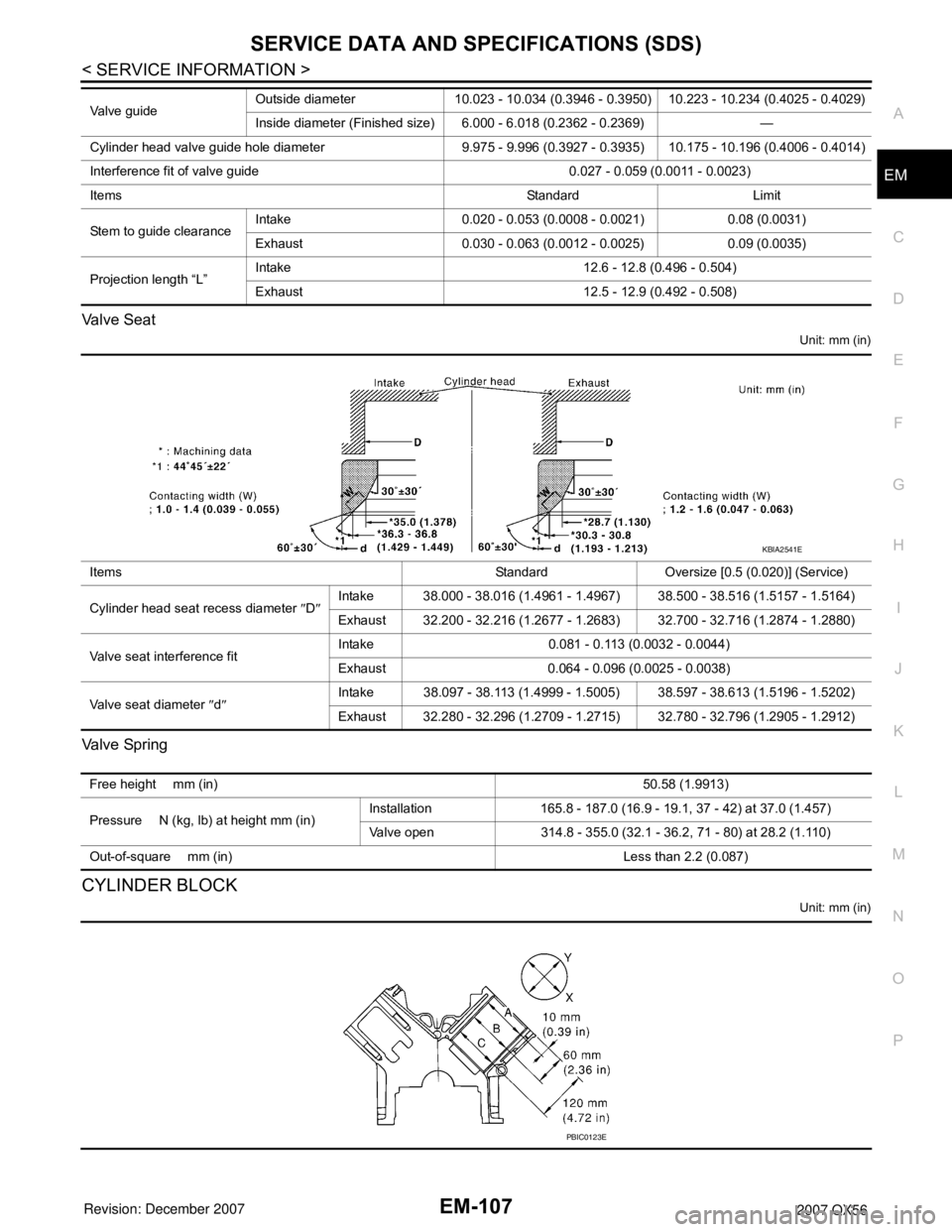
P O Valve Seat
Unit: mm (in)
Va l v e Sp r i n g
CYLINDER BLOCK
Unit: mm (in)
Valve guideOutside diameter 10.023 - 10.034 (0.3946 - 0.3950) 10.223 - 10.234 (0.4025 - 0.4029)
Inside diameter (Finished size) 6.000 - 6.018 (0.2362 - 0.2369) —
Cylinder head valve guide hole diameter 9.975 - 9.996 (0.3927 - 0.3935) 10.175 - 10.196 (0.4006 - 0.4014)
Interference fit of valve guide 0.027 - 0.059 (0.0011 - 0.0023)
Items Standard Limit
Stem to guide clearanceIntake 0.020 - 0.053 (0.0008 - 0.0021) 0.08 (0.0031)
Exhaust 0.030 - 0.063 (0.0012 - 0.0025) 0.09 (0.0035)
Projection length “L”Intake 12.6 - 12.8 (0.496 - 0.504)
Exhaust 12.5 - 12.9 (0.492 - 0.508)
Items Standard Oversize [0.5 (0.020)] (Service)
Cylinder head seat recess diameter ″D″Intake 38.000 - 38.016 (1.4961 - 1.4967) 38.500 - 38.516 (1.5157 - 1.5164)
Exhaust 32.200 - 32.216 (1.2677 - 1.2683) 32.700 - 32.716 (1.2874 - 1.2880)
Valve seat interference fitIntake 0.081 - 0.113 (0.0032 - 0.0044)
Exhaust 0.064 - 0.096 (0.0025 - 0.0038)
Valve seat diameter ″d″Intake 38.097 - 38.113 (1.4999 - 1.5005) 38.597 - 38.613 (1.5196 - 1.5202)
Exhaust 32.280 - 32.296 (1.2709 - 1.2715) 32.780 - 32.796 (1.2905 - 1.2912)
KBIA2541E
Free height mm (in)50.58 (1.9913)
Pressure N (kg, lb) at height mm (in)Installation 165.8 - 187.0 (16.9 - 19.1, 37 - 42) at 37.0 (1.457)
Valve open 314.8 - 355.0 (32.1 - 36.2, 71 - 80) at 28.2 (1.110)
Out-of-square mm (in) Less than 2.2 (0.087)
PBIC0123E