Page 2555 of 3061

SUNROOF
RF-23
< SERVICE INFORMATION >
C
D
E
F
G
H
J
K
L
MA
B
RF
N
O
P
3. Adjust the glass lid assembly. Refer to RF-20, "Fitting Adjustment".
4. Install side cover LH and RH.
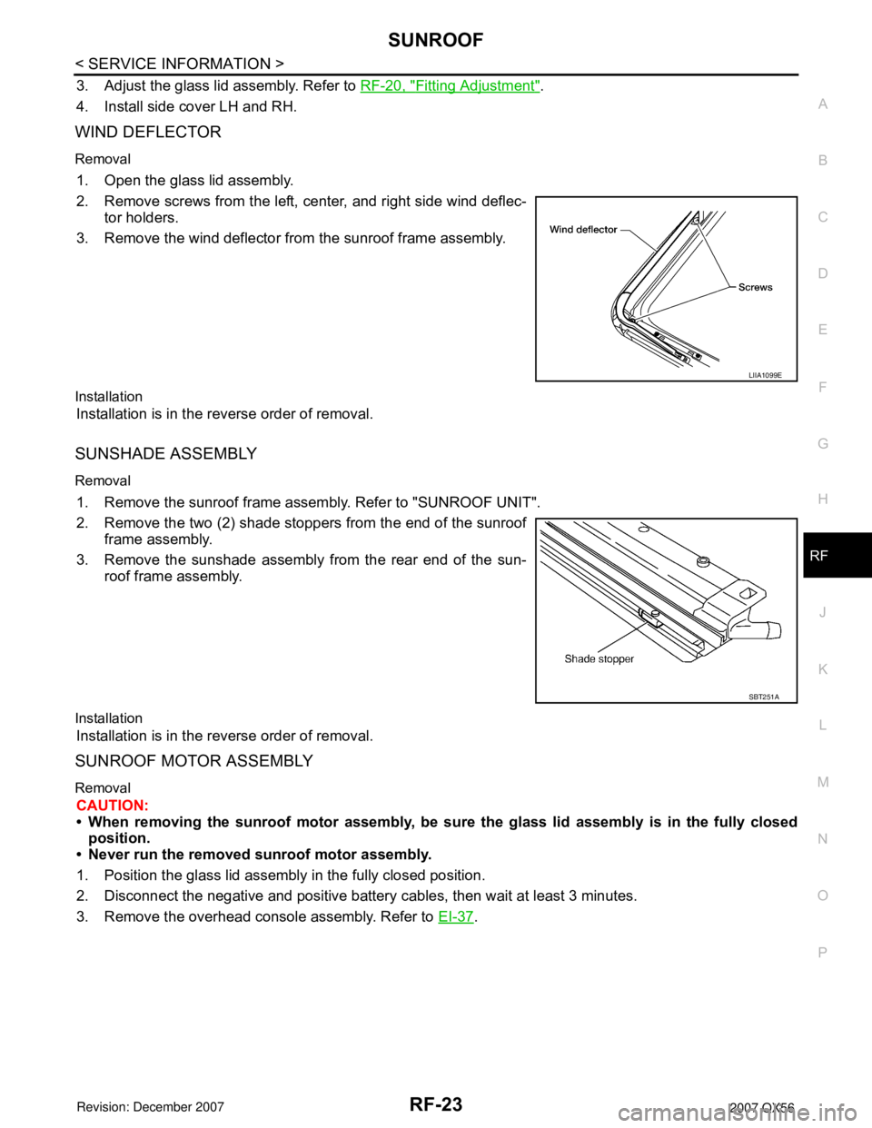
WIND DEFLECTOR
Removal
1. Open the glass lid assembly.
2. Remove screws from the left, center, and right side wind deflec-
tor holders.
3. Remove the wind deflector from the sunroof frame assembly.
Installation
Installation is in the reverse order of removal.
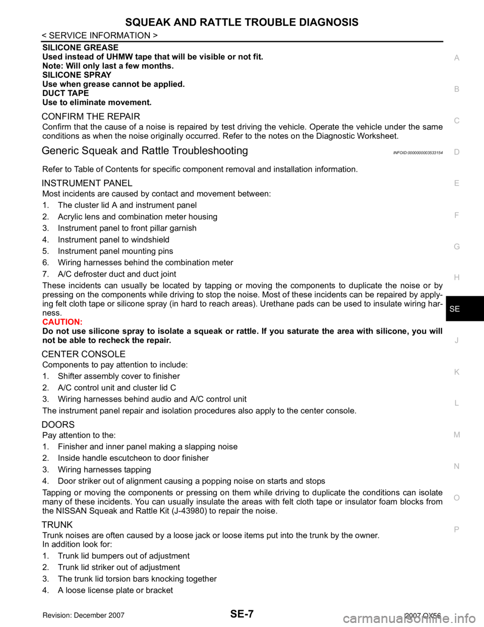
SUNSHADE ASSEMBLY
Removal
1. Remove the sunroof frame assembly. Refer to "SUNROOF UNIT".
2. Remove the two (2) shade stoppers from the end of the sunroof
frame assembly.
3. Remove the sunshade assembly from the rear end of the sun-
roof frame assembly.
Installation
Installation is in the reverse order of removal.
SUNROOF MOTOR ASSEMBLY
Removal
CAUTION:
• When removing the sunroof motor assembly, be sure the glass lid assembly is in the fully closed
position.
• Never run the removed sunroof motor assembly.
1. Position the glass lid assembly in the fully closed position.
2. Disconnect the negative and positive battery cables, then wait at least 3 minutes.
3. Remove the overhead console assembly. Refer to EI-37
.
LIIA1099E
SBT251A
Page 2679 of 3061

SQUEAK AND RATTLE TROUBLE DIAGNOSIS
SE-7
< SERVICE INFORMATION >
C
D
E
F
G
H
J
K
L
MA
B
SE
N
O
P
SILICONE GREASE
Used instead of UHMW tape that will be visible or not fit.
Note: Will only last a few months.
SILICONE SPRAY
Use when grease cannot be applied.
DUCT TAPE
Use to eliminate movement.
CONFIRM THE REPAIR
Confirm that the cause of a noise is repaired by test driving the vehicle. Operate the vehicle under the same
conditions as when the noise originally occurred. Refer to the notes on the Diagnostic Worksheet.
Generic Squeak and Rattle TroubleshootingINFOID:0000000003533154
Refer to Table of Contents for specific component removal and installation information.
INSTRUMENT PANEL
Most incidents are caused by contact and movement between:
1. The cluster lid A and instrument panel
2. Acrylic lens and combination meter housing
3. Instrument panel to front pillar garnish
4. Instrument panel to windshield
5. Instrument panel mounting pins
6. Wiring harnesses behind the combination meter
7. A/C defroster duct and duct joint
These incidents can usually be located by tapping or moving the components to duplicate the noise or by
pressing on the components while driving to stop the noise. Most of these incidents can be repaired by apply-
ing felt cloth tape or silicone spray (in hard to reach areas). Urethane pads can be used to insulate wiring har-
ness.
CAUTION:
Do not use silicone spray to isolate a squeak or rattle. If you saturate the area with silicone, you will
not be able to recheck the repair.
CENTER CONSOLE
Components to pay attention to include:
1. Shifter assembly cover to finisher
2. A/C control unit and cluster lid C
3. Wiring harnesses behind audio and A/C control unit
The instrument panel repair and isolation procedures also apply to the center console.
DOORS
Pay attention to the:
1. Finisher and inner panel making a slapping noise
2. Inside handle escutcheon to door finisher
3. Wiring harnesses tapping
4. Door striker out of alignment causing a popping noise on starts and stops
Tapping or moving the components or pressing on them while driving to duplicate the conditions can isolate
many of these incidents. You can usually insulate the areas with felt cloth tape or insulator foam blocks from
the NISSAN Squeak and Rattle Kit (J-43980) to repair the noise.
TRUNK
Trunk noises are often caused by a loose jack or loose items put into the trunk by the owner.
In addition look for:
1. Trunk lid bumpers out of adjustment
2. Trunk lid striker out of adjustment
3. The trunk lid torsion bars knocking together
4. A loose license plate or bracket
Page 2710 of 3061

SE-38
< SERVICE INFORMATION >
AUTOMATIC DRIVE POSITIONER
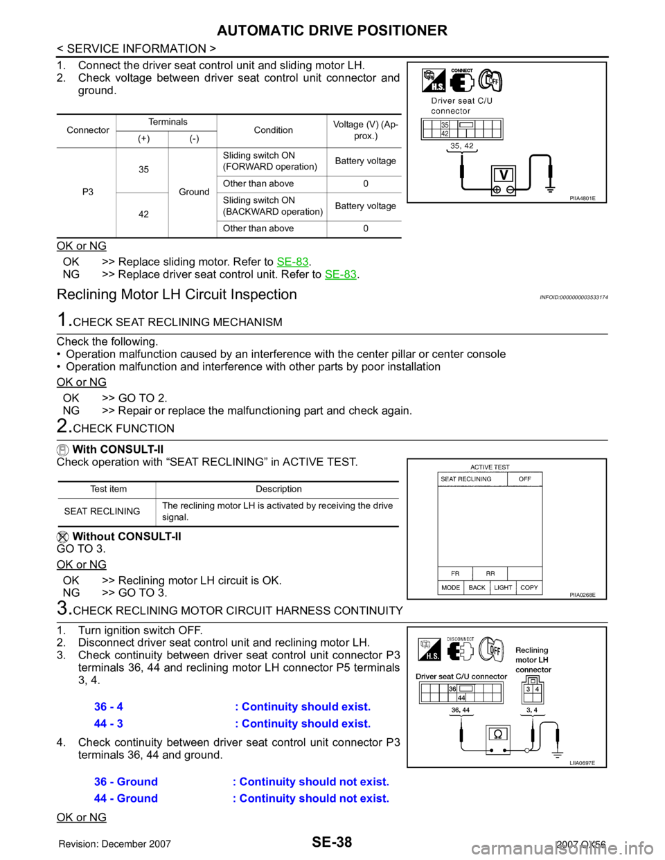
1. Connect the driver seat control unit and sliding motor LH.
2. Check voltage between driver seat control unit connector and
ground.
OK or NG
OK >> Replace sliding motor. Refer to SE-83.
NG >> Replace driver seat control unit. Refer to SE-83
.
Reclining Motor LH Circuit InspectionINFOID:0000000003533174
1.CHECK SEAT RECLINING MECHANISM
Check the following.
• Operation malfunction caused by an interference with the center pillar or center console
• Operation malfunction and interference with other parts by poor installation
OK or NG
OK >> GO TO 2.
NG >> Repair or replace the malfunctioning part and check again.
2.CHECK FUNCTION
With CONSULT-II
Check operation with “SEAT RECLINING” in ACTIVE TEST.
Without CONSULT-II
GO TO 3.
OK or NG
OK >> Reclining motor LH circuit is OK.
NG >> GO TO 3.
3.CHECK RECLINING MOTOR CIRCUIT HARNESS CONTINUITY
1. Turn ignition switch OFF.
2. Disconnect driver seat control unit and reclining motor LH.
3. Check continuity between driver seat control unit connector P3
terminals 36, 44 and reclining motor LH connector P5 terminals
3, 4.
4. Check continuity between driver seat control unit connector P3
terminals 36, 44 and ground.
OK or NG
ConnectorTe r m i n a l s
ConditionVoltage (V) (Ap-
prox.)
(+) (-)
P335
GroundSliding switch ON
(FORWARD operation)Battery voltage
Other than above 0
42Sliding switch ON
(BACKWARD operation)Battery voltage
Other than above 0
PIIA4801E
Test item Description
SEAT RECLININGThe reclining motor LH is activated by receiving the drive
signal.
PIIA0268E
36 - 4 : Continuity should exist.
44 - 3 : Continuity should exist.
36 - Ground : Continuity should not exist.
44 - Ground : Continuity should not exist.
LIIA0697E
Page 2817 of 3061

DIAGNOSIS SENSOR UNIT
SRS-47
< SERVICE INFORMATION >
C
D
E
F
G
I
J
K
L
MA
B
SRS
N
O
P
DIAGNOSIS SENSOR UNIT
Removal and InstallationINFOID:0000000003532880
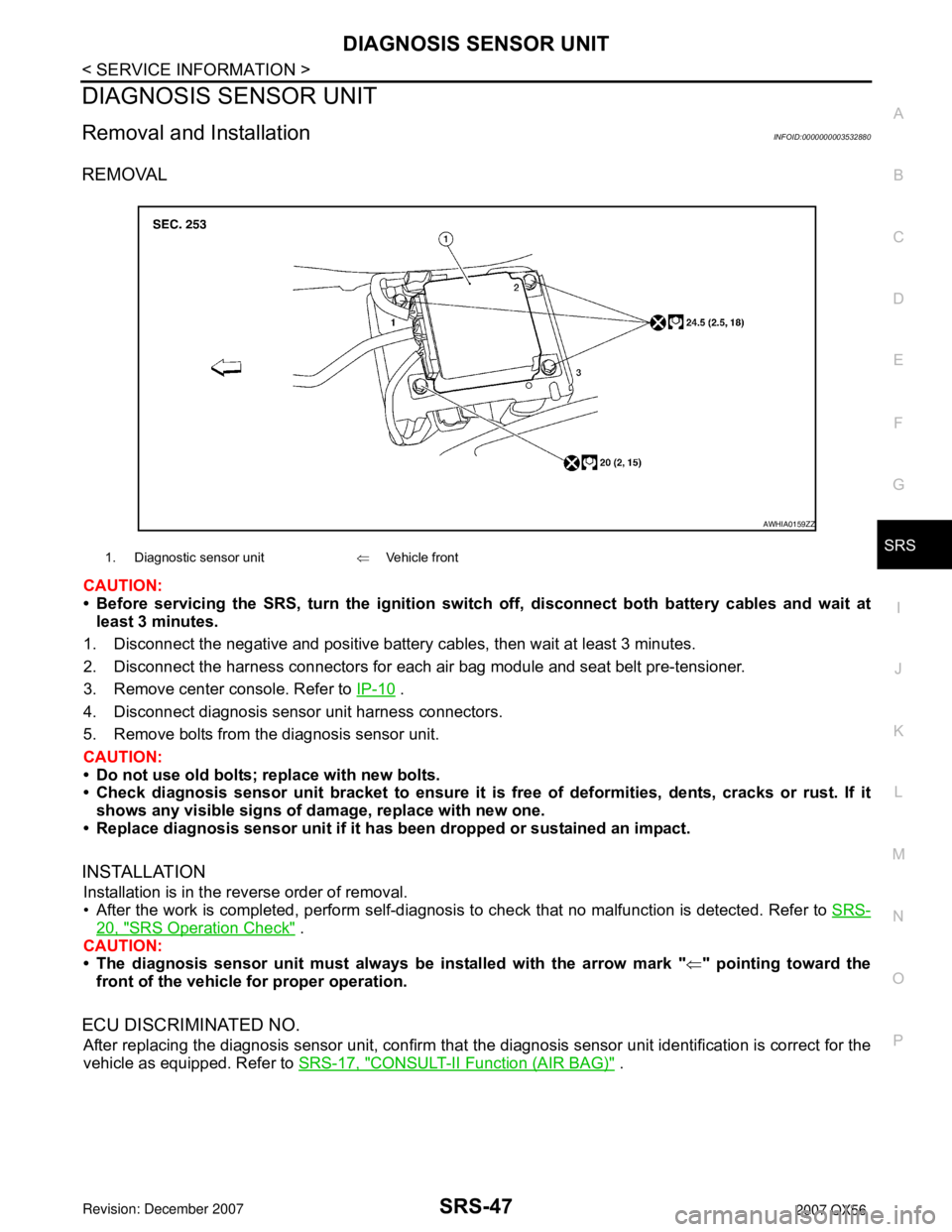
REMOVAL
CAUTION:
• Before servicing the SRS, turn the ignition switch off, disconnect both battery cables and wait at
least 3 minutes.
1. Disconnect the negative and positive battery cables, then wait at least 3 minutes.
2. Disconnect the harness connectors for each air bag module and seat belt pre-tensioner.
3. Remove center console. Refer to IP-10
.
4. Disconnect diagnosis sensor unit harness connectors.
5. Remove bolts from the diagnosis sensor unit.
CAUTION:
• Do not use old bolts; replace with new bolts.
• Check diagnosis sensor unit bracket to ensure it is free of deformities, dents, cracks or rust. If it
shows any visible signs of damage, replace with new one.
• Replace diagnosis sensor unit if it has been dropped or sustained an impact.
INSTALLATION
Installation is in the reverse order of removal.
• After the work is completed, perform self-diagnosis to check that no malfunction is detected. Refer to SRS-
20, "SRS Operation Check" .
CAUTION:
• The diagnosis sensor unit must always be installed with the arrow mark "⇐" pointing toward the
front of the vehicle for proper operation.
ECU DISCRIMINATED NO.
After replacing the diagnosis sensor unit, confirm that the diagnosis sensor unit identification is correct for the
vehicle as equipped. Refer to SRS-17, "
CONSULT-II Function (AIR BAG)" .
1. Diagnostic sensor unit⇐Vehicle front
AWHIA0159ZZ