Page 2744 of 3061

SE-72
< SERVICE INFORMATION >
AUTOMATIC DRIVE POSITIONER
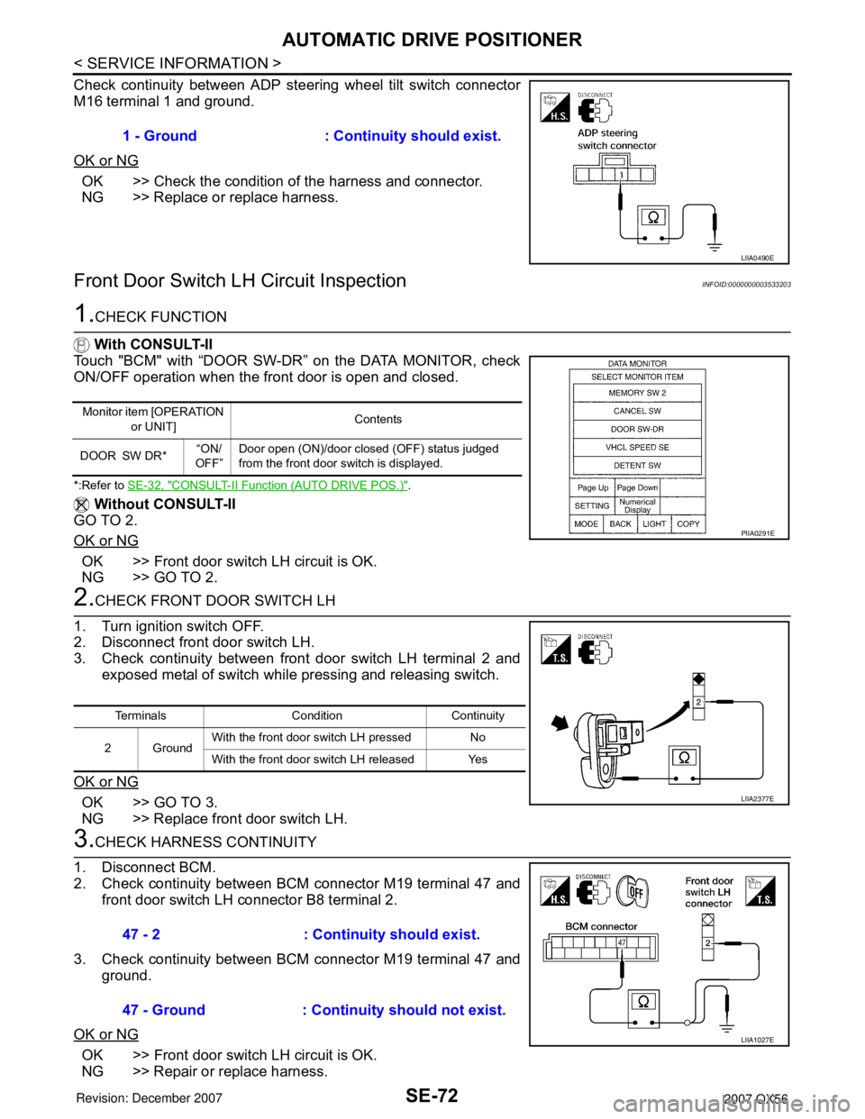
Check continuity between ADP steering wheel tilt switch connector
M16 terminal 1 and ground.
OK or NG
OK >> Check the condition of the harness and connector.
NG >> Replace or replace harness.
Front Door Switch LH Circuit InspectionINFOID:0000000003533203
1.CHECK FUNCTION
With CONSULT-II
Touch "BCM" with “DOOR SW-DR” on the DATA MONITOR, check
ON/OFF operation when the front door is open and closed.
*:Refer to SE-32, "CONSULT-II Function (AUTO DRIVE POS.)".
Without CONSULT-II
GO TO 2.
OK or NG
OK >> Front door switch LH circuit is OK.
NG >> GO TO 2.
2.CHECK FRONT DOOR SWITCH LH
1. Turn ignition switch OFF.
2. Disconnect front door switch LH.
3. Check continuity between front door switch LH terminal 2 and
exposed metal of switch while pressing and releasing switch.
OK or NG
OK >> GO TO 3.
NG >> Replace front door switch LH.
3.CHECK HARNESS CONTINUITY
1. Disconnect BCM.
2. Check continuity between BCM connector M19 terminal 47 and
front door switch LH connector B8 terminal 2.
3. Check continuity between BCM connector M19 terminal 47 and
ground.
OK or NG
OK >> Front door switch LH circuit is OK.
NG >> Repair or replace harness.1 - Ground : Continuity should exist.
LIIA0490E
Monitor item [OPERATION
or UNIT]Contents
DOOR SW DR*“ON/
OFF”Door open (ON)/door closed (OFF) status judged
from the front door switch is displayed.
PIIA0291E
Terminals Condition Continuity
2GroundWith the front door switch LH pressed No
With the front door switch LH released Yes
LIIA2377E
47 - 2 : Continuity should exist.
47 - Ground : Continuity should not exist.
LIIA1027E
Page 2745 of 3061

AUTOMATIC DRIVE POSITIONER
SE-73
< SERVICE INFORMATION >
C
D
E
F
G
H
J
K
L
MA
B
SE
N
O
P
UART Communication Line Circuit InspectionINFOID:0000000003533204
1.CHECK UART LINE INPUT/OUTPUT SIGNAL 1
1. Turn ignition switch OFF.
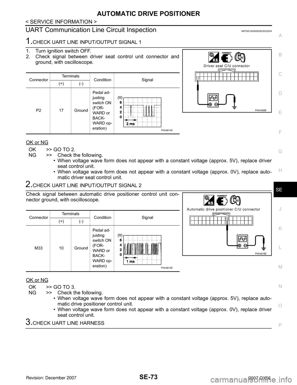
2. Check signal between driver seat control unit connector and
ground, with oscilloscope.
OK or NG
OK >> GO TO 2.
NG >> Check the following.
• When voltage wave form does not appear with a constant voltage (approx. 5V), replace driver
seat control unit.
• When voltage wave form does not appear with a constant voltage (approx. 0V), replace auto-
matic driver seat control unit.
2.CHECK UART LINE INPUT/OUTPUT SIGNAL 2
Check signal between automatic drive positioner control unit con-
nector ground, with oscilloscope.
OK or NG
OK >> GO TO 3.
NG >> Check the following.
• When voltage wave form does not appear with a constant voltage (approx. 5V), replace auto-
matic drive positioner control unit.
• When voltage wave form does not appear with a constant voltage (approx. 0V), replace driver
seat control unit.
3.CHECK UART LINE HARNESS
ConnectorTe r m i n a l s
Condition Signal
(+) (-)
P2 17 GroundPedal ad-
justing
switch ON
(FOR-
WARD or
BACK-
WARD op-
eration)
PIIA4599E
PIIA4814E
ConnectorTe r m i n a l s
Condition Signal
(+) (-)
M33 10 GroundPedal ad-
justing
switch ON
(FOR-
WARD or
BACK-
WARD op-
eration)
PIIA4816E
PIIA4813E
Page 2746 of 3061
SE-74
< SERVICE INFORMATION >
AUTOMATIC DRIVE POSITIONER
1. Disconnect driver seat control unit and automatic drive posi-
tioner control unit.
2. Check continuity between driver seat control unit connector P2
terminals 1, 17, and automatic drive positioner connector M33
terminals 10, 26.
3. Check continuity between driver seat control unit connector P2
terminals 1, 17 and ground.
OK or NG
OK >> GO TO 4.
NG >> Repair or replace harness.
4.CHECK DRIVER SEAT CONTROL UNIT
Does the automatic drive positioner operate when the driver seat control unit is exchanged?
OK or NG
OK >> Replace driver seat control unit.
NG >> Replace automatic drive positioner control unit.
Removal and InstallationINFOID:0000000003533205
Refer to ACC-3 and BR-5 . 1 - 10 : Continuity should exist.
17 - 26 : Continuity should exist.
1 - Ground : Continuity should not exist.
17 - Ground : Continuity should not exist.
PIIA4598E
Page 2747 of 3061
POWER SEAT
SE-75
< SERVICE INFORMATION >
C
D
E
F
G
H
J
K
L
MA
B
SE
N
O
P
POWER SEAT
Wiring Diagram - SEAT - for Passenger SeatINFOID:0000000003533206
WIWA1406E
Page 2748 of 3061
SE-76
< SERVICE INFORMATION >
HEATED SEAT
HEATED SEAT
DescriptionINFOID:0000000003533207
• When handling seat, be extremely careful not to scratch heating unit.
• Front passenger seat cushion and seatbacks equipped with airbags cannot be disassembled. They are
replaced as assemblies only.
• Do not use any organic solvent, such as thinner, benzene, alcohol, etc. to clean trim.
WIIA0031E
Page 2749 of 3061
HEATED SEAT
SE-77
< SERVICE INFORMATION >
C
D
E
F
G
H
J
K
L
MA
B
SE
N
O
P
SchematicINFOID:0000000003533208
WIWA0586E
Page 2750 of 3061
SE-78
< SERVICE INFORMATION >
HEATED SEAT
Wiring Diagram - HSEAT -
INFOID:0000000003533209
WIWA0587E
Page 2751 of 3061
HEATED SEAT
SE-79
< SERVICE INFORMATION >
C
D
E
F
G
H
J
K
L
MA
B
SE
N
O
P
WIWA0588E