2007 INFINITI QX56 sensor
[x] Cancel search: sensorPage 1027 of 3061
DI-16
< SERVICE INFORMATION >
COMBINATION METERS
Perform self-diagnosis mode of combination meter. Refer to DI-12, "Self-Diagnosis Mode of Combination
Meter".
Does self-diagnosis mode operate normally?
YES >> GO TO 3.
NO >> Check combination meter power supply and ground circuit. Refer to DI-16, "
Power Supply and
Ground Circuit Inspection".
3.CHECK ODOMETER OPERATION
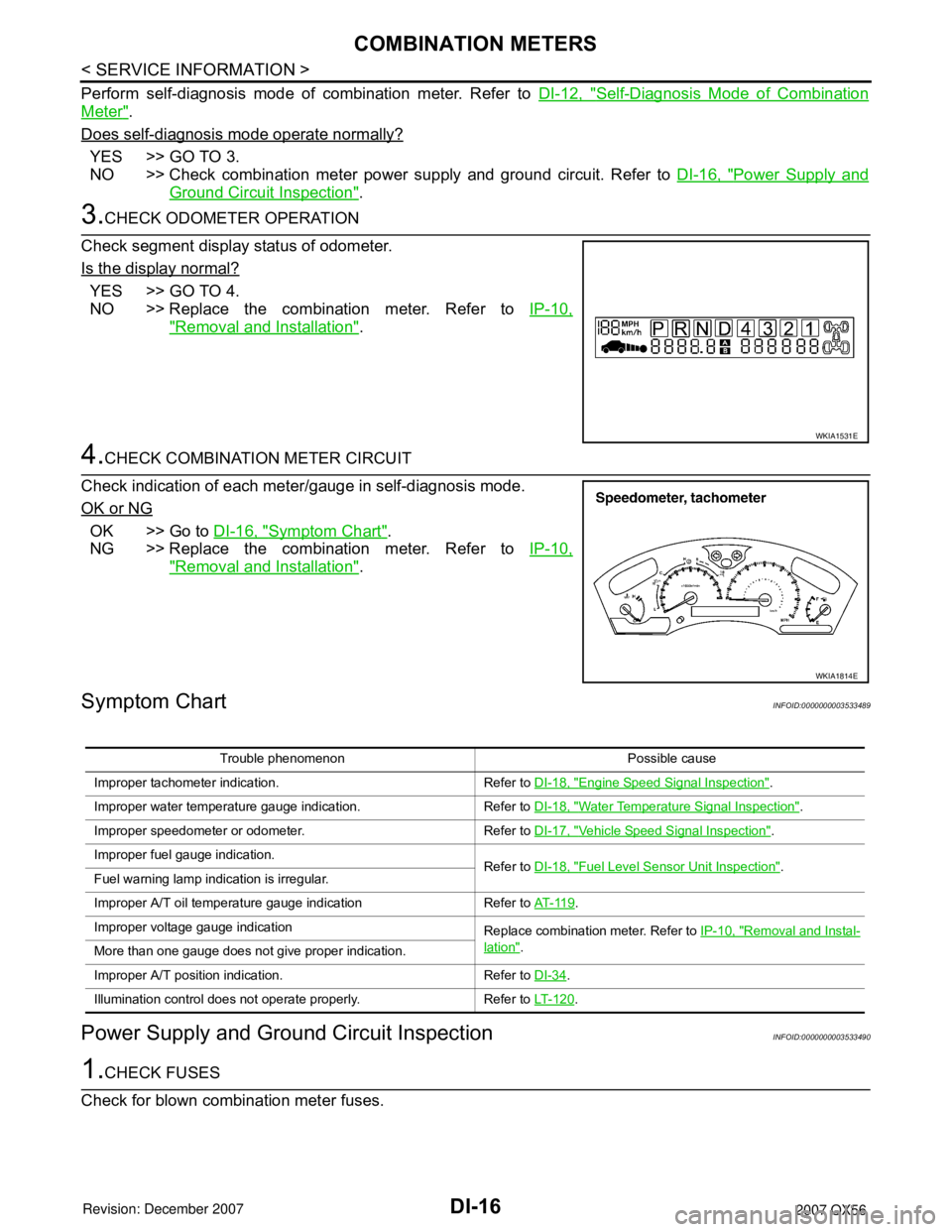
Check segment display status of odometer.
Is the display normal?
YES >> GO TO 4.
NO >> Replace the combination meter. Refer to IP-10,
"Removal and Installation".
4.CHECK COMBINATION METER CIRCUIT
Check indication of each meter/gauge in self-diagnosis mode.
OK or NG
OK >> Go to DI-16, "Symptom Chart".
NG >> Replace the combination meter. Refer to IP-10,
"Removal and Installation".
Symptom ChartINFOID:0000000003533489
Power Supply and Ground Circuit InspectionINFOID:0000000003533490
1.CHECK FUSES
Check for blown combination meter fuses.
WKIA1531E
WKIA1814E
Trouble phenomenon Possible cause
Improper tachometer indication. Refer to DI-18, "
Engine Speed Signal Inspection".
Improper water temperature gauge indication. Refer to DI-18, "
Water Temperature Signal Inspection".
Improper speedometer or odometer. Refer to DI-17, "
Vehicle Speed Signal Inspection".
Improper fuel gauge indication. Refer to DI-18, "
Fuel Level Sensor Unit Inspection".
Fuel warning lamp indication is irregular.
Improper A/T oil temperature gauge indication Refer to AT- 11 9
.
Improper voltage gauge indication Replace combination meter. Refer to IP-10, "
Removal and Instal-
lation".
More than one gauge does not give proper indication.
Improper A/T position indication. Refer to DI-34
.
Illumination control does not operate properly. Refer to LT- 1 2 0
.
Page 1029 of 3061
DI-18
< SERVICE INFORMATION >
COMBINATION METERS
Self-diagnostic results content
No malfunction detected>>GO TO 2.
Malfunction detected>>GO TO PG-18, "
CONSULT-II Function (IPDM E/R)".
2.CHECK IPDM E/R INPUT SIGNAL
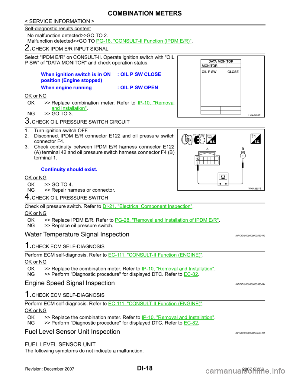
Select "IPDM E/R" on CONSULT-II. Operate ignition switch with "OIL
P SW" of "DATA MONITOR" and check operation status.
OK or NG
OK >> Replace combination meter. Refer to IP-10, "Removal
and Installation".
NG >> GO TO 3.
3.CHECK OIL PRESSURE SWITCH CIRCUIT
1. Turn ignition switch OFF.
2. Disconnect IPDM E/R connector E122 and oil pressure switch
connector F4.
3. Check continuity between IPDM E/R harness connector E122 (A) terminal 42 and oil pressure switch harness connector F4 (B)
terminal 1.
OK or NG
OK >> GO TO 4.
NG >> Repair harness or connector.
4.CHECK OIL PRESSURE SWITCH
Check oil pressure switch. Refer to DI-21, "
Electrical Component Inspection".
OK or NG
OK >> Replace IPDM E/R. Refer to PG-28, "Removal and Installation of IPDM E/R".
NG >> Replace oil pressure switch.
Water Temperature Signal InspectionINFOID:0000000003533493
1.CHECK ECM SELF-DIAGNOSIS
Perform ECM self-diagnosis. Refer to E C - 111 , "
CONSULT-II Function (ENGINE)".
OK or NG
OK >> Replace the combination meter. Refer to IP-10, "Removal and Installation".
NG >> Perform "Diagnostic procedure" for displayed DTC. Refer to EC-82
.
Engine Speed Signal InspectionINFOID:0000000003533494
1.CHECK ECM SELF-DIAGNOSIS
Perform ECM self-diagnosis. Refer to E C - 111 , "
CONSULT-II Function (ENGINE)".
OK or NG
OK >> Replace the combination meter. Refer to IP-10, "Removal and Installation".
NG >> Perform "Diagnostic procedure" for displayed DTC. Refer to EC-82
.
Fuel Level Sensor Unit InspectionINFOID:0000000003533495
FUEL LEVEL SENSOR UNIT
The following symptoms do not indicate a malfunction.When ignition switch is in ON
position (Engine stopped)
: OIL P SW CLOSE
When engine running : OIL P SW OPEN
LKIA0403E
Continuity should exist.
WKIA5607E
Page 1030 of 3061
COMBINATION METERSDI-19
< SERVICE INFORMATION >
C
DE
F
G H
I
J
L
M A
B
DI
N
O P
• Depending on vehicle position or driving circumstance, the fuel in the tank shifts and the indication may fluc-
tuate.
• If the vehicle is fueled with the ignition switch ON, the indication will update slowly.
• If the vehicle is tilted when the ignition switch is turned ON, fuel in the tank may flow to one direction result-
ing in a change of reading.
LOW-FUEL WARNING LAMP
Depending on vehicle posture or driving circumstances, the fuel level in the tank varies, and the warning lamp
ON timing may be changed.
1.CHECK SELF-DIAGNOSIS
Perform the combination meter self-diagnosis. Refer to DI-12, "
Self-Diagnosis Mode of Combination Meter".
OK or NG
OK >> GO TO 2.
NG >> Replace the combination meter. Refer to IP-10, "
Removal and Installation".
2.CHECK HARNESS CONNECTOR
1. Turn the ignition switch OFF.
2. Check combination meter and fuel level sensor unit and fuel pump terminals (meter-side, and harness-
side) for poor connection.
OK or NG
OK >> GO TO 3.
NG >> Repair or replace terminals or connectors.
3.CHECK HARNESS CONNECTOR OUTPUT SIGNAL
1. Disconnect fuel level sensor unit and fuel pump connector.
2. Turn ignition switch ON.
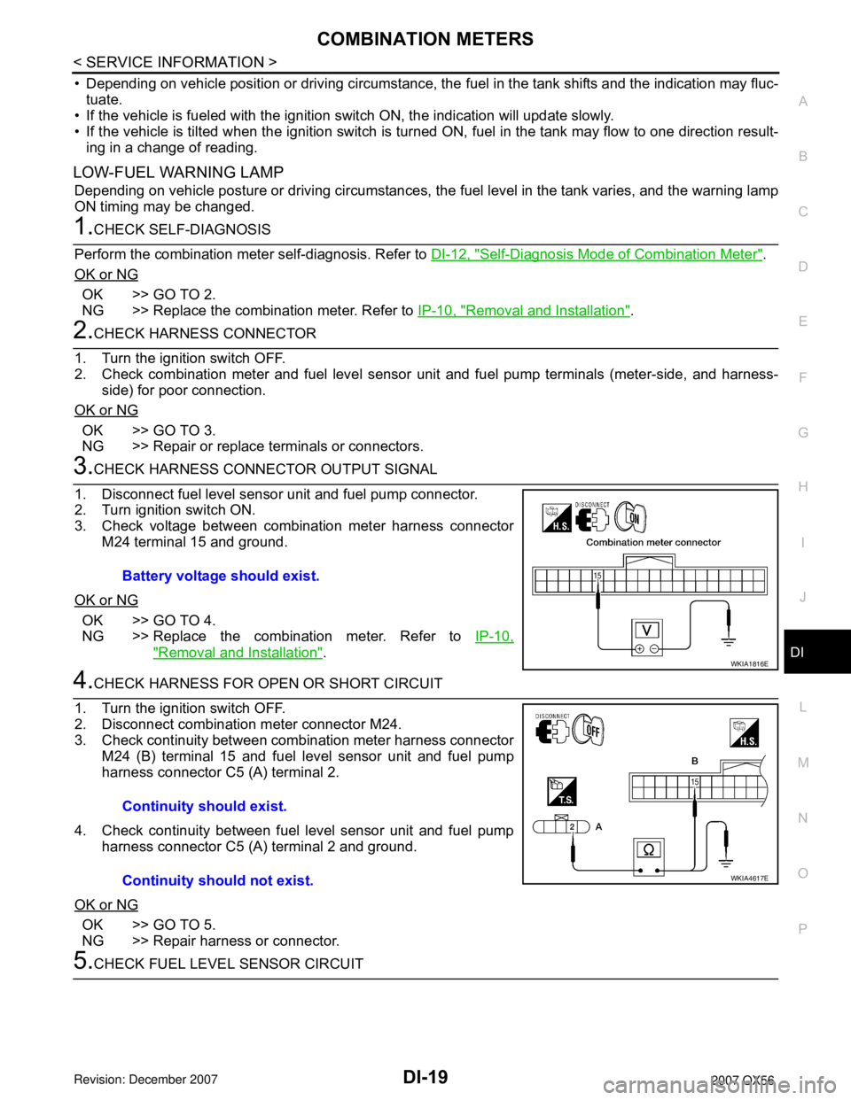
3. Check voltage between combination meter harness connector M24 terminal 15 and ground.
OK or NG
OK >> GO TO 4.
NG >> Replace the combination meter. Refer to IP-10,
"Removal and Installation".
4.CHECK HARNESS FOR OPEN OR SHORT CIRCUIT
1. Turn the ignition switch OFF.
2. Disconnect combination meter connector M24.
3. Check continuity between combination meter harness connector M24 (B) terminal 15 and fuel level sensor unit and fuel pump
harness connector C5 (A) terminal 2.
4. Check continuity between fuel level sensor unit and fuel pump harness connector C5 (A) terminal 2 and ground.
OK or NG
OK >> GO TO 5.
NG >> Repair harness or connector.
5.CHECK FUEL LEVEL SENSOR CIRCUIT Battery voltage should exist.
WKIA1816E
Continuity should exist.
Continuity should not exist.
WKIA4617E
Page 1031 of 3061
DI-20
< SERVICE INFORMATION >
COMBINATION METERS
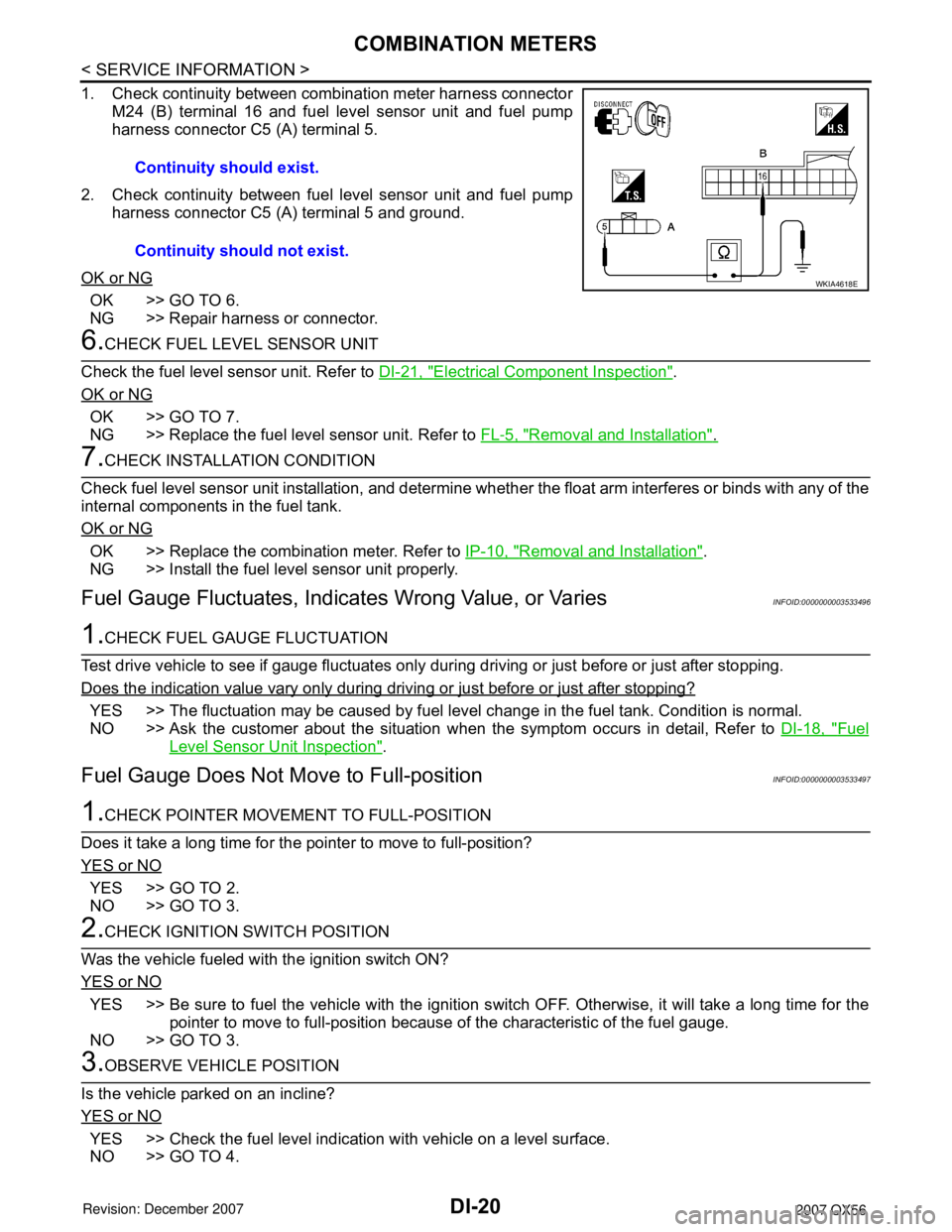
1. Check continuity between combination meter harness connectorM24 (B) terminal 16 and fuel level sensor unit and fuel pump
harness connector C5 (A) terminal 5.
2. Check continuity between fuel level sensor unit and fuel pump harness connector C5 (A) terminal 5 and ground.
OK or NG
OK >> GO TO 6.
NG >> Repair harness or connector.
6.CHECK FUEL LEVEL SENSOR UNIT
Check the fuel level sensor unit. Refer to DI-21, "
Electrical Component Inspection".
OK or NG
OK >> GO TO 7.
NG >> Replace the fuel level sensor unit. Refer to FL-5, "
Removal and Installation".
7.CHECK INSTALLATION CONDITION
Check fuel level sensor unit installation, and determine whet her the float arm interferes or binds with any of the
internal components in the fuel tank.
OK or NG
OK >> Replace the combination meter. Refer to IP-10, "Removal and Installation".
NG >> Install the fuel level sensor unit properly.
Fuel Gauge Fluctuat es, Indicates Wrong Value, or VariesINFOID:0000000003533496
1.CHECK FUEL GAUGE FLUCTUATION
Test drive vehicle to see if gauge fluctuates only during driving or just before or just after stopping.
Does the indication value vary only during driving or just before or just after stopping?
YES >> The fluctuation may be caused by fuel leve l change in the fuel tank. Condition is normal.
NO >> Ask the customer about the situation when the symptom occurs in detail, Refer to DI-18, "
Fuel
Level Sensor Unit Inspection".
Fuel Gauge Does Not Move to Full-positionINFOID:0000000003533497
1.CHECK POINTER MOVEME NT TO FULL-POSITION
Does it take a long time for the pointer to move to full-position?
YES or NO
YES >> GO TO 2.
NO >> GO TO 3.
2.CHECK IGNITION SWITCH POSITION
Was the vehicle fueled with the ignition switch ON?
YES or NO
YES >> Be sure to fuel the vehicle with the ignition s witch OFF. Otherwise, it will take a long time for the
pointer to move to full-position because of the characteristic of the fuel gauge.
NO >> GO TO 3.
3.OBSERVE VEHICLE POSITION
Is the vehicle parked on an incline?
YES or NO
YES >> Check the fuel level indication with vehicle on a level surface.
NO >> GO TO 4. Continuity should exist.
Continuity should not exist.
WKIA4618E
Page 1032 of 3061
COMBINATION METERS
DI-21
< SERVICE INFORMATION >
C
D
E
F
G
H
I
J
L
MA
B
DI
N
O
P
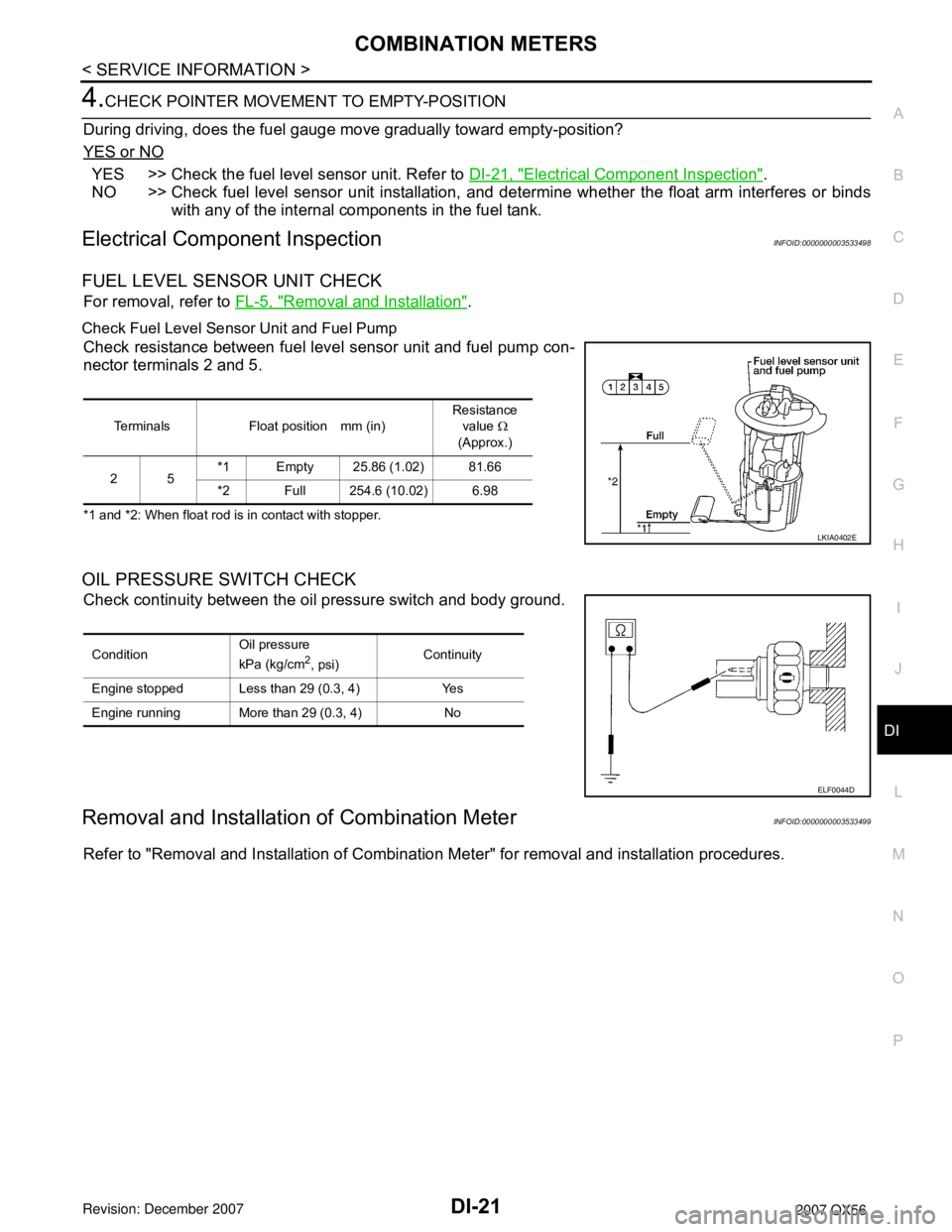
4.CHECK POINTER MOVEMENT TO EMPTY-POSITION
During driving, does the fuel gauge move gradually toward empty-position?
YES or NO
YES >> Check the fuel level sensor unit. Refer to DI-21, "Electrical Component Inspection".
NO >> Check fuel level sensor unit installation, and determine whether the float arm interferes or binds
with any of the internal components in the fuel tank.
Electrical Component InspectionINFOID:0000000003533498
FUEL LEVEL SENSOR UNIT CHECK
For removal, refer to FL-5, "Removal and Installation".
Check Fuel Level Sensor Unit and Fuel Pump
Check resistance between fuel level sensor unit and fuel pump con-
nector terminals 2 and 5.
*1 and *2: When float rod is in contact with stopper.
OIL PRESSURE SWITCH CHECK
Check continuity between the oil pressure switch and body ground.
Removal and Installation of Combination MeterINFOID:0000000003533499
Refer to "Removal and Installation of Combination Meter" for removal and installation procedures.
Terminals Float position mm (in)Resistance
value Ω
(Approx.)
25*1 Empty 25.86 (1.02) 81.66
*2 Full 254.6 (10.02) 6.98
LKIA0402E
ConditionOil pressure
kPa (kg/cm2, psi)Continuity
Engine stopped Less than 29 (0.3, 4) Yes
Engine running More than 29 (0.3, 4) No
ELF0044D
Page 1035 of 3061

DI-24
< SERVICE INFORMATION >
COMPASS AND THERMOMETER
1. Turn the ignition switch to the ON position.
2. Cool down ambient sensor 2 with water or ice.
Does the indicated temperature drop?
YES >> GO TO 2.
NO >> The system is malfunctioning. Check the system following “INSPECTION/COMPASS AND THER-
MOMETER”. Refer to "INSPECTION/COMPASS AND THERMOMETER".
2.WARM UP CHECK
1. Leave the vehicle for 10 minutes.
2. With the ignition switch in the ON position, disconnect and reconnect ambient sensor 2 connector.
Does the indicated temperature rise?
YES >> The system is OK.
NO >> The system is malfunctioning. Check the system following “INSPECTION/COMPASS AND THER-
MOMETER”. Refer to "INSPECTION/COMPASS AND THERMOMETER".
INSPECTION/COMPASS AND THERMOMETER
Calibration Procedure for CompassINFOID:0000000003533503
The difference between magnetic North and geographical North can sometimes be great enough to cause
false compass readings. In order for the compass to operate accurately in a particular zone, it must be cali-
brated using the following procedure.
Symptom Possible causes Repair order
No display at all 1. 10A fuse.
2. Ground circuit.
3. auto anti-dazzling inside mirror.1. Check 10A fuse [No. 12, located in fuse block (J/B)].
Turn the ignition switch ON and verify that battery positive
voltage is at terminal 6 of auto anti-dazzling inside mirror.
2. Check ground circuit for auto anti-dazzling inside mirror.
3. Replace auto anti-dazzling inside mirror.
Forward direction indi-
cation slips off the mark
or incorrect.1. In manual correction mode (Bar
and display vanish).
2. Zone variation change is not
done.1. Drive the vehicle and turn at an angle of 90°.
2. Perform the zone variation change.
Displays wrong temper-
ature when ambient
temperature is between
−40°C (−40°F) and
55°C (130°F)1. Check operation.
2. Ambient sensor 2 circuit.
3. Ambient sensor 2.
4. Auto anti-dazzling inside mirror.1. Perform preliminary check shown above.
2. Check harness for open or short between ambient sensor 2
and auto anti-dazzling inside mirror.
3. Replace ambient sensor 2.
4. Replace auto anti-dazzling inside mirror.
Displays SC or OC 1. Ambient sensor 2 circuit.
2. Ambient sensor 2.
3. Auto anti-dazzling inside mirror.1. Check harness for open or short between ambient sensor 2
and auto anti-dazzling inside mirror.
2. Replace ambient sensor 2.
3. Replace auto anti-dazzling inside mirror.
Page 1057 of 3061
DI-46
< SERVICE INFORMATION >
REAR SONAR SYSTEM
REAR SONAR SYSTEM
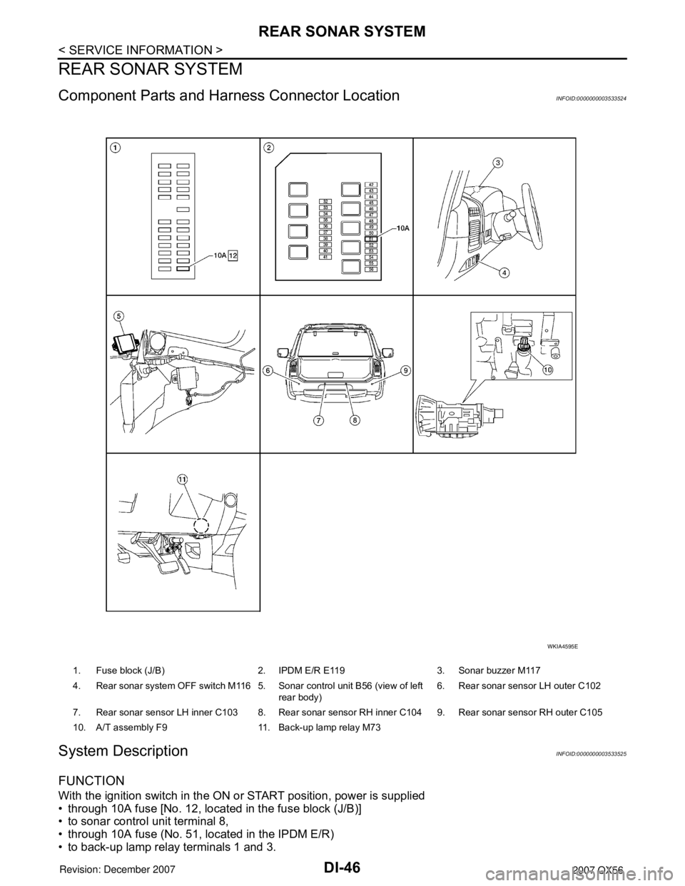
Component Parts and Harness Connector LocationINFOID:0000000003533524
System DescriptionINFOID:0000000003533525
FUNCTION
With the ignition switch in the ON or START position, power is supplied
• through 10A fuse [No. 12, located in the fuse block (J/B)]
• to sonar control unit terminal 8,
• through 10A fuse (No. 51, located in the IPDM E/R)
• to back-up lamp relay terminals 1 and 3.
1. Fuse block (J/B) 2. IPDM E/R E119 3. Sonar buzzer M117
4. Rear sonar system OFF switch M116 5. Sonar control unit B56 (view of left
rear body)6. Rear sonar sensor LH outer C102
7. Rear sonar sensor LH inner C103 8. Rear sonar sensor RH inner C104 9. Rear sonar sensor RH outer C105
10. A/T assembly F9 11. Back-up lamp relay M73
WKIA4595E
Page 1058 of 3061

REAR SONAR SYSTEM
DI-47
< SERVICE INFORMATION >
C
D
E
F
G
H
I
J
L
MA
B
DI
N
O
P
Ground is supplied
• to sonar control unit terminal 6
• through body grounds B7 and B19.
With the ignition switch in the ON or START position, and the transmission gear selector lever in the R posi-
tion, power is supplied
• to sonar control unit terminal 5
• from back-up lamp relay terminal 5.
With power and ground supplied, transmission gear selector lever in R position, and the rear sonar system
OFF switch ON, the rear sonar system will detect obstacles within 1.8 m (5.9 ft.) of the rear sonar sensors. The
vehicle operator is notified of obstacles by varied rate of tone from the sonar buzzer depending on distance of
obstacle being sensed.
REAR SONAR SYSTEM OFF SWITCH
With power and ground supplied to the sonar control unit, transmission gear selector lever in R position, the
sonar system can be disabled and the sonar buzzer silenced by momentarily pressing the rear sonar system
OFF switch. The rear sonar system OFF indicator lamp will be illuminated in the rear sonar system OFF
switch.
To disable the rear sonar system, ground is supplied
• to sonar control unit terminal 13
• through rear sonar system OFF switch terminal 1
• through rear sonar system OFF switch terminal 2
• from body grounds M57, M61, and M79.
To light the rear sonar system OFF indicator, power is supplied
• from sonar control unit terminal 4
• to the rear sonar system OFF switch terminal 5.
Ground is supplied
• to the rear sonar system OFF switch terminal 6
• from body grounds M57, M61, and M79.
The rear sonar system and buzzer will be disabled and the rear sonar system OFF indicator will be illuminated
until the ignition switch is turned OFF. When the ignition switch is turned ON, the rear sonar system will be
enabled. Depressing the rear sonar system OFF switch momentarily will enable the rear sonar system also.
Enabling the rear sonar system will cause the rear sonar system OFF indicator to go out.
SONAR BUZZER
With power supplied to the sonar control unit and the transmission gear selector lever in R position, a station-
ary object that is at least 7.0 cm (2.8 in.) wide and 1.0 m (39.0 in.) tall and that is closer than 1.8 meters (5.9 ft.)
will be detected by the rear sonar sensors, causing the sonar buzzer to sound a tone. As the vehicle moves
closer to the object, the rate of the tone will increase. When the object is less than 25.0 cm (10 in.) from the
rear bumper, the tone will sound continuously.
Power is supplied
• from sonar control unit terminal 7
• to sonar buzzer terminal +.
Ground is supplied
• to sonar buzzer terminal -
• from sonar control unit terminal 3.
REAR SONAR SENSOR
With power and ground supplied to the rear sonar sensors, the sonar sensors transmit a 38.4 kHz ultrasonic
signal. This signal is reflected back to the sensor by objects large enough and close enough to be detected.
The rear sonar sensors measure the time from the transmitted signal to the time the signal is reflected back
and sends this information to the sonar control unit.
Power is supplied
• from sonar control unit terminal 16
• to each rear sonar sensor terminal 1.
Ground is supplied
• to each rear sonar sensor terminal 3
• from sonar control unit terminal 15.
Signal is supplied
• from each rear sonar sensor terminal 2
• to sonar control unit terminals 9, 10, 11 and 12.