Page 2462 of 3061

PG-60
< SERVICE INFORMATION >
HARNESS
Code Section Wiring Diagram Name
A/C,A ATC Auto Air Conditioner
A/SUSP RSU Rear Air Suspension
AF1B1 EC Air Fuel Ratio (A/F) Sensor 1 (Bank 1)
AF1B2 EC Air Fuel Ratio (A/F) Sensor 1 (Bank 2)
AF1HB1 EC Air Fuel Ratio (A/F) Sensor 1 (Bank 1)
AF1HB2 EC Air Fuel Ratio (A/F) Sensor 1 (Bank 2)
APPS1 EC Accelerator Pedal Position Sensor
APPS2 EC Accelerator Pedal Position Sensor
APPS3 EC Accelerator Pedal Position Sensor
ASC/BS EC ASCD Brake Switch
ASC/SW EC ASCD Steering Switch
ASCBOF EC ASCD Brake Switch
ASCIND EC ASCD Indicator
A/T AT A/T Assembly
AT/IND DI A/T Indicator Lamp
AUDIO AV Audio
AUT/DP SE Automatic Drive Positioner
AUTO/L LT Auto Light Control
B/CLOS BL Back Door Auto Closure System
BACK/L LT Back-up Lamp
BRK/SW EC Brake Switch
CAN EC CAN Communication Line
CAN LAN CAN System
CHARGE SC Charging System
CHIME DI Warning Chime
CLOCK DI Clock
COOL/F EC Cooling Fan Control
COMBSW LT Combination Switch
COMM AV Audio Visual Communication System
COMPAS DI Compass and Thermometer
D/LOCK BL Power Door Lock
DEF GW Rear Window Defogger
DTRL LT Headlamp - With Daytime Light System
DVD AV DVD Entertainment System
ECM/PW EC ECM Power Supply for Back-Up
ECTS EC Engine Coolant Temperature Sensor
ETC1 EC Electric Throttle Control Function
ETC2 EC Throttle Control Motor Relay
ETC3 EC Throttle Control Motor
F/FOG LT Front Fog Lamp
F/PUMP EC Fuel Pump
FTTS EC Fuel Tank Temperature Sensor
FUELB1 EC Fuel Injection System Bank 1
FUELB2 EC Fuel Injection System Bank 2
H/AIM LT Headlamp Aiming Control
H/PHON AV Hands Free Telephone
H/LAMP LT Headlamp
HORN WW Horn
HSEAT SE Heated Seat
ICC ACS Intelligent Cruise Control
ICCBOF EC ICC Brake Switch
Page 2533 of 3061

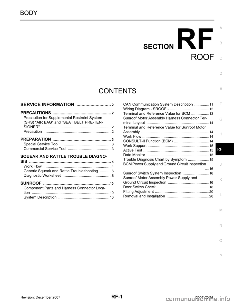
RF-1
BODY
C
D
E
F
G
H
J
K
L
M
SECTION RF
A
B
RF
N
O
P
CONTENTS
ROOF
SERVICE INFORMATION ............................2
PRECAUTIONS ...................................................2
Precaution for Supplemental Restraint System
(SRS) "AIR BAG" and "SEAT BELT PRE-TEN-
SIONER" ...................................................................
2
Precaution .................................................................2
PREPARATION ...................................................3
Special Service Tool .................................................3
Commercial Service Tool ..........................................3
SQUEAK AND RATTLE TROUBLE DIAGNO-
SIS .......................................................................
4
Work Flow .................................................................4
Generic Squeak and Rattle Troubleshooting ............6
Diagnostic Worksheet ...............................................8
SUNROOF ..........................................................10
Component Parts and Harness Connector Loca-
tion ..........................................................................
10
System Description .................................................10
CAN Communication System Description ...............11
Wiring Diagram - SROOF - ......................................12
Terminal and Reference Value for BCM ..................13
Sunroof Motor Assembly Harness Connector Ter-
minal Layout ............................................................
14
Terminal and Reference Value for Sunroof Motor
Assembly .................................................................
14
Work Flow ................................................................14
CONSULT-II Function (BCM) ..................................14
Work Support ...........................................................15
Active Test ...............................................................15
Data Monitor ............................................................15
Trouble Diagnosis Chart by Symptom .....................15
BCM Power Supply and Ground Circuit Inspection
....
16
Sunroof Switch System Inspection ..........................16
Sunroof Motor Assembly Power Supply and
Ground Circuit Inspection ........................................
16
Door Switch Check ..................................................18
Fitting Adjustment ....................................................20
Removal and Installation .........................................20
Page 2544 of 3061
RF-12
< SERVICE INFORMATION >
SUNROOF
Wiring Diagram - SROOF -
INFOID:0000000003533098
WIWA0170E
Page 2591 of 3061

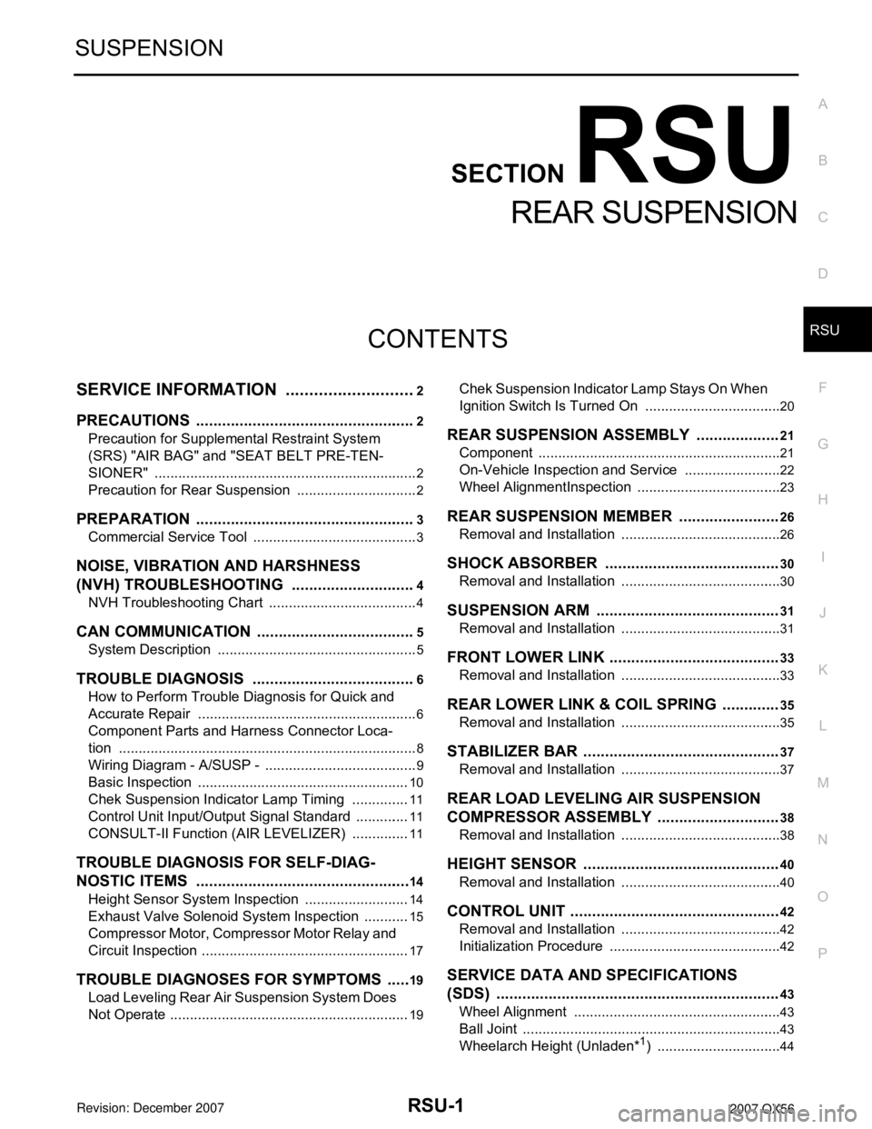
RSU-1
SUSPENSION
C
D
F
G
H
I
J
K
L
M
SECTION RSU
A
B
RSU
N
O
PCONTENTS
REAR SUSPENSION
SERVICE INFORMATION ............................2
PRECAUTIONS ...................................................2
Precaution for Supplemental Restraint System
(SRS) "AIR BAG" and "SEAT BELT PRE-TEN-
SIONER" ...................................................................
2
Precaution for Rear Suspension ...............................2
PREPARATION ...................................................3
Commercial Service Tool ..........................................3
NOISE, VIBRATION AND HARSHNESS
(NVH) TROUBLESHOOTING .............................
4
NVH Troubleshooting Chart ......................................4
CAN COMMUNICATION .....................................5
System Description ...................................................5
TROUBLE DIAGNOSIS ......................................6
How to Perform Trouble Diagnosis for Quick and
Accurate Repair ........................................................
6
Component Parts and Harness Connector Loca-
tion ............................................................................
8
Wiring Diagram - A/SUSP - .......................................9
Basic Inspection ......................................................10
Chek Suspension Indicator Lamp Timing ...............11
Control Unit Input/Output Signal Standard ..............11
CONSULT-II Function (AIR LEVELIZER) ...............11
TROUBLE DIAGNOSIS FOR SELF-DIAG-
NOSTIC ITEMS ..................................................
14
Height Sensor System Inspection ...........................14
Exhaust Valve Solenoid System Inspection ............15
Compressor Motor, Compressor Motor Relay and
Circuit Inspection .....................................................
17
TROUBLE DIAGNOSES FOR SYMPTOMS ......19
Load Leveling Rear Air Suspension System Does
Not Operate .............................................................
19
Chek Suspension Indicator Lamp Stays On When
Ignition Switch Is Turned On ...................................
20
REAR SUSPENSION ASSEMBLY ...................21
Component ..............................................................21
On-Vehicle Inspection and Service .........................22
Wheel AlignmentInspection .....................................23
REAR SUSPENSION MEMBER .......................26
Removal and Installation .........................................26
SHOCK ABSORBER ........................................30
Removal and Installation .........................................30
SUSPENSION ARM ..........................................31
Removal and Installation .........................................31
FRONT LOWER LINK .......................................33
Removal and Installation .........................................33
REAR LOWER LINK & COIL SPRING .............35
Removal and Installation .........................................35
STABILIZER BAR .............................................37
Removal and Installation .........................................37
REAR LOAD LEVELING AIR SUSPENSION
COMPRESSOR ASSEMBLY ............................
38
Removal and Installation .........................................38
HEIGHT SENSOR .............................................40
Removal and Installation .........................................40
CONTROL UNIT ................................................42
Removal and Installation .........................................42
Initialization Procedure ............................................42
SERVICE DATA AND SPECIFICATIONS
(SDS) .................................................................
43
Wheel Alignment .....................................................43
Ball Joint ..................................................................43
Wheelarch Height (Unladen*1) ................................44
Page 2599 of 3061
TROUBLE DIAGNOSIS
RSU-9
< SERVICE INFORMATION >
C
D
F
G
H
I
J
K
L
MA
B
RSU
N
O
P
Wiring Diagram - A/SUSP -INFOID:0000000003532659
WEWA0049E
Page 2649 of 3061

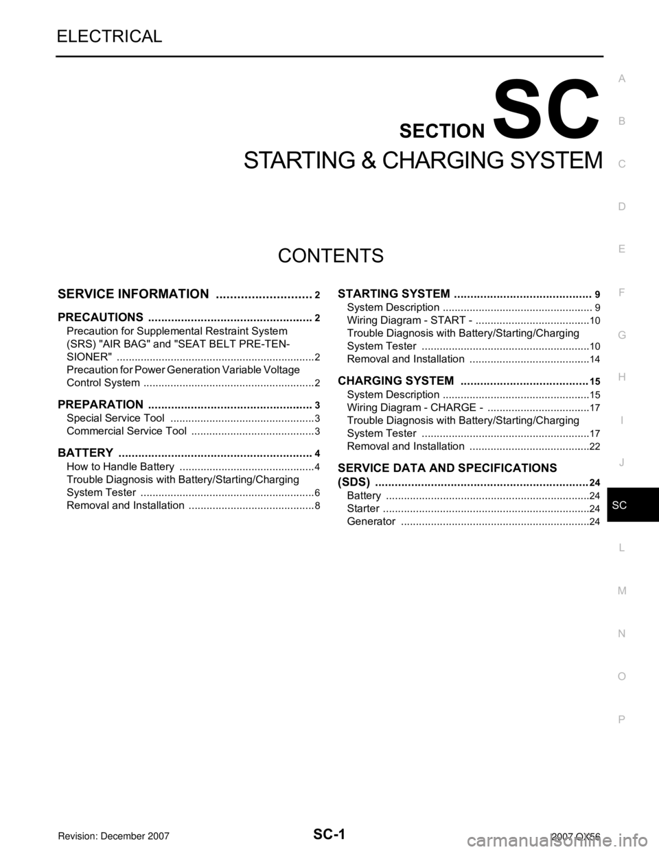
SC-1
ELECTRICAL
C
D
E
F
G
H
I
J
L
M
SECTION SC
A
B
SC
N
O
P
CONTENTS
STARTING & CHARGING SYSTEM
SERVICE INFORMATION ............................2
PRECAUTIONS ...................................................2
Precaution for Supplemental Restraint System
(SRS) "AIR BAG" and "SEAT BELT PRE-TEN-
SIONER" ...................................................................
2
Precaution for Power Generation Variable Voltage
Control System ..........................................................
2
PREPARATION ...................................................3
Special Service Tool .................................................3
Commercial Service Tool ..........................................3
BATTERY ............................................................4
How to Handle Battery ..............................................4
Trouble Diagnosis with Battery/Starting/Charging
System Tester ...........................................................
6
Removal and Installation ...........................................8
STARTING SYSTEM ..........................................9
System Description ...................................................9
Wiring Diagram - START - .......................................10
Trouble Diagnosis with Battery/Starting/Charging
System Tester .........................................................
10
Removal and Installation .........................................14
CHARGING SYSTEM .......................................15
System Description ..................................................15
Wiring Diagram - CHARGE - ...................................17
Trouble Diagnosis with Battery/Starting/Charging
System Tester .........................................................
17
Removal and Installation .........................................22
SERVICE DATA AND SPECIFICATIONS
(SDS) .................................................................
24
Battery .....................................................................24
Starter ......................................................................24
Generator ................................................................24
Page 2658 of 3061
SC-10
< SERVICE INFORMATION >
STARTING SYSTEM
Wiring Diagram - START -
INFOID:0000000003533320
Trouble Diagnosis with Battery/Starting/Charging System TesterINFOID:0000000003533321
NOTE:
To ensure a complete and thorough diagnosis, the battery, starter and generator test segments must be done
as a set from start to finish.
AWBWA0151G
Page 2665 of 3061
CHARGING SYSTEM
SC-17
< SERVICE INFORMATION >
C
D
E
F
G
H
I
J
L
MA
B
SC
N
O
P
Wiring Diagram - CHARGE -INFOID:0000000003533324
Trouble Diagnosis with Battery/Starting/Charging System TesterINFOID:0000000003533325
NOTE:
To ensure a complete and thorough diagnosis, the battery, starter and generator test segments must be done
as a set from start to finish.
WKWA5141E