2007 INFINITI QX56 wiring diagram
[x] Cancel search: wiring diagramPage 2111 of 3061
IDX-7
A
C
D
E
F
G
H
I
J
K
L B
IDX
ALPHABETICAL INDEX
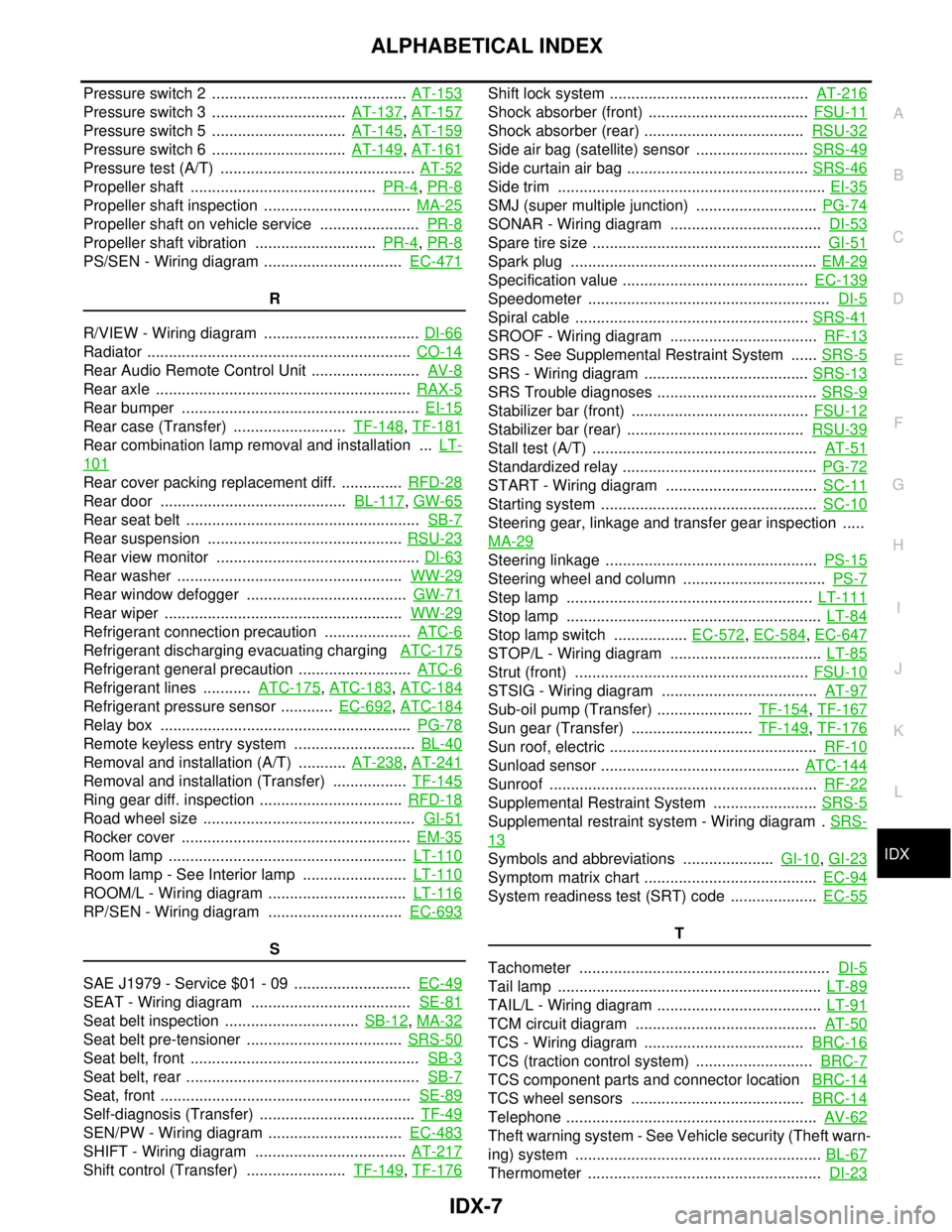
Pressure switch 2 ............................................. AT-153
Pressure switch 3 ............................... AT-137, AT-157
Pressure switch 5 ............................... AT-145, AT-159
Pressure switch 6 ............................... AT-149, AT-161
Pressure test (A/T) ............................................. AT-52
Propeller shaft ........................................... PR-4, PR-8
Propeller shaft inspection .................................. MA-25
Propeller shaft on vehicle service ....................... PR-8
Propeller shaft vibration ............................ PR-4, PR-8
PS/SEN - Wiring diagram ................................ EC-471
R
R/VIEW - Wiring diagram .................................... DI-66
Radiator ............................................................. CO-14
Rear Audio Remote Control Unit ......................... AV-8
Rear axle ........................................................... RAX-5
Rear bumper ....................................................... EI-15
Rear case (Transfer) .......................... TF-148, TF-181
Rear combination lamp removal and installation ... LT-
101
Rear cover packing replacement diff. .............. RFD-28
Rear door ........................................... BL-117, GW-65
Rear seat belt ...................................................... SB-7
Rear suspension ............................................. RSU-23
Rear view monitor ............................................... DI-63
Rear washer .................................................... WW-29
Rear window defogger ..................................... GW-71
Rear wiper ....................................................... WW-29
Refrigerant connection precaution .................... ATC-6
Refrigerant discharging evacuating charging ATC-175
Refrigerant general precaution .......................... ATC-6
Refrigerant lines ........... ATC-175, ATC-183, ATC-184
Refrigerant pressure sensor ............ EC-692, ATC-184
Relay box .......................................................... PG-78
Remote keyless entry system ............................ BL-40
Removal and installation (A/T) ........... AT-238, AT-241
Removal and installation (Transfer) ................. TF-145
Ring gear diff. inspection ................................. RFD-18
Road wheel size ................................................. GI-51
Rocker cover ..................................................... EM-35
Room lamp ....................................................... LT-110
Room lamp - See Interior lamp ........................ LT-110
ROOM/L - Wiring diagram ................................ LT-116
RP/SEN - Wiring diagram ............................... EC-693
S
SAE J1979 - Service $01 - 09 ........................... EC-49
SEAT - Wiring diagram ..................................... SE-81
Seat belt inspection ............................... SB-12, MA-32
Seat belt pre-tensioner .................................... SRS-50
Seat belt, front ..................................................... SB-3
Seat belt, rear ...................................................... SB-7
Seat, front .......................................................... SE-89
Self-diagnosis (Transfer) .................................... TF-49
SEN/PW - Wiring diagram ............................... EC-483
SHIFT - Wiring diagram ................................... AT-217
Shift control (Transfer) ....................... TF-149, TF-176
Shift lock system .............................................. AT-216
Shock absorber (front) ..................................... FSU-11
Shock absorber (rear) ..................................... RSU-32
Side air bag (satellite) sensor .......................... SRS-49
Side curtain air bag .......................................... SRS-46
Side trim .............................................................. EI-35
SMJ (super multiple junction) ............................ PG-74
SONAR - Wiring diagram ................................... DI-53
Spare tire size ..................................................... GI-51
Spark plug ......................................................... EM-29
Specification value ........................................... EC-139
Speedometer ........................................................ DI-5
Spiral cable ...................................................... SRS-41
SROOF - Wiring diagram .................................. RF-13
SRS - See Supplemental Restraint System ...... SRS-5
SRS - Wiring diagram ...................................... SRS-13
SRS Trouble diagnoses ..................................... SRS-9
Stabilizer bar (front) ......................................... FSU-12
Stabilizer bar (rear) ......................................... RSU-39
Stall test (A/T) .................................................... AT-51
Standardized relay ............................................. PG-72
START - Wiring diagram ................................... SC-11
Starting system .................................................. SC-10
Steering gear, linkage and transfer gear inspection .....
MA-29
Steering linkage ................................................. PS-15
Steering wheel and column ................................. PS-7
Step lamp ......................................................... LT-111
Stop lamp ........................................................... LT-84
Stop lamp switch ................. EC-572, EC-584, EC-647
STOP/L - Wiring diagram ................................... LT-85
Strut (front) ...................................................... FSU-10
STSIG - Wiring diagram .................................... AT-97
Sub-oil pump (Transfer) ...................... TF-154, TF-167
Sun gear (Transfer) ............................ TF-149, TF-176
Sun roof, electric ................................................ RF-10
Sunload sensor .............................................. ATC-144
Sunroof .............................................................. RF-22
Supplemental Restraint System ........................ SRS-5
Supplemental restraint system - Wiring diagram . SRS-
13
Symbols and abbreviations ..................... GI-10, GI-23
Symptom matrix chart ........................................ EC-94
System readiness test (SRT) code .................... EC-55
T
Tachometer .......................................................... DI-5
Tail lamp ............................................................. LT-89
TAIL/L - Wiring diagram ...................................... LT-91
TCM circuit diagram .......................................... AT-50
TCS - Wiring diagram ..................................... BRC-16
TCS (traction control system) ........................... BRC-7
TCS component parts and connector location BRC-14
TCS wheel sensors ........................................ BRC-14
Telephone .......................................................... AV-62
Theft warning system - See Vehicle security (Theft warn-
ing) system ......................................................... BL-67
Thermometer ...................................................... DI-23
Page 2112 of 3061
IDX-8
ALPHABETICAL INDEX
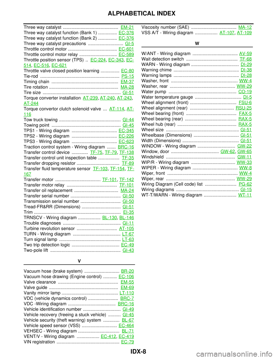
Three way catalyst ............................................ EM-21
Three way catalyst function (Bank 1) ............... EC-376
Three way catalyst function (Bank 2) ............... EC-376
Three way catalyst precautions ............................ GI-5
Throttle control motor ....................................... EC-601
Throttle control motor relay .............................. EC-589
Throttle position sensor (TPS) .. EC-224, EC-343, EC-
514, EC-516, EC-621
Throttle valve closed position learning ............... EC-80
Tie-rod ............................................................... PS-15
Timing chain ..................................................... EM-37
Tire rotation ....................................................... MA-28
Tire size .............................................................. GI-51
Torque converter installation AT-239, AT-240, AT-243,
AT-244
Torque convertor clutch solenoid valve ... AT-114, AT-
116
Tow truck towing ................................................. GI-44
Towing point ....................................................... GI-45
TPS1 - Wiring diagram .................................... EC-345
TPS2 - Wiring diagram .................................... EC-226
TPS3 - Wiring diagram .................................... EC-623
Traction control system - Wiring diagram ....... BRC-16
Transfer control device ............. TF-75, TF-79, TF-138
Transfer control unit inspection table ................. TF-35
Transfer dropping resistor .................................. TF-89
Transfer fluid temperature sensor TF-103, TF-154, TF-
167
Transfer motor .................................... TF-101, TF-142
Transfer motor relay ........................................ TF-101
Transfer oil replacement ................................... MA-24
Transfer serial number ........................................ GI-50
Transmission serial number ................................ GI-50
Tread-FR&RR (Dimensions) ............................... GI-51
Trim ..................................................................... EI-35
TRNSCV - Wiring diagram .................. BL-130, BL-146
Trouble diagnoses .............................................. GI-11
Turbine revolution sensor ................................ AT-105
TURN - Wiring diagram ...................................... LT-67
Turn signal lamp ................................................. LT-63
Two trip detection logic ...................................... EC-49
Two-pole lift ........................................................ GI-43
V
Vacuum hose (brake system) ............................ BR-20
Vacuum hose drawing (Engine control) ........... EC-106
Valve clearance ................................................ EM-55
Valve guide ....................................................... EM-69
Vanity mirror lamp ............................................. LT-110
VDC (vehicle dynamics control) ........................ BRC-7
VDC -Wiring diagram ...................................... BRC-16
Vehicle identification number .............................. GI-49
Vehicle recovery (freeing a stuck vehicle) .......... GI-45
Vehicle security (theft warning) system ............. BL-67
Vehicle speed sensor (VSS) ............................ EC-464
VEHSEC - Wiring diagram ................................. BL-71
VENT/V - Wiring diagram .................. EC-412, EC-419
VIN registration .................................................. EC-79
Viscosity number (SAE) .................................... MA-12
VSS A/T - Wiring diagram .................. AT-107, AT-109
W
W/ANT - Wiring diagram .................................... AV-59
Wait detection switch ......................................... TF-68
WARN - Wiring diagram ...................................... DI-29
Warning chime .................................................... DI-38
Warning lamps .................................................... DI-28
Washer, front ..................................................... WW-4
Washer, rear .................................................... WW-29
Water pump ...................................................... CO-19
Water temperature gauge ..................................... DI-5
Wheel alignment (front) ..................................... FSU-6
Wheel alignment (rear) ................................... RSU-25
Wheel bearing (front) ........................................ FAX-5
Wheel bearing (rear) ......................................... RAX-5
Wheel hub (rear) ............................................... RAX-5
Wheel size .......................................................... GI-51
Wheelbase (Dimensions) .................................... GI-51
Width (Dimensions) ............................................. GI-51
WINDOW - Wiring diagram .............................. GW-22
Window, door ...................................... GW-62, GW-65
Windshield ....................................................... GW-11
WIP/R - Wiring diagram ................................... WW-33
WIPER - Wiring diagram .................................... WW-8
Wiper, front ........................................................ WW-4
Wiper, rear ....................................................... WW-29
Wiring Diagram (Cell code) list ......................... PG-62
Wiring diagrams .................................................. GI-15
WT-T/WARN - Wiring diagram .......................... WT-11
Page 2132 of 3061
LAN-1
ELECTRICAL
C
D
E
F
G
H
I
J
L
M
SECTION LAN
A
B
LAN
N
O
P
CONTENTS
LAN SYSTEM
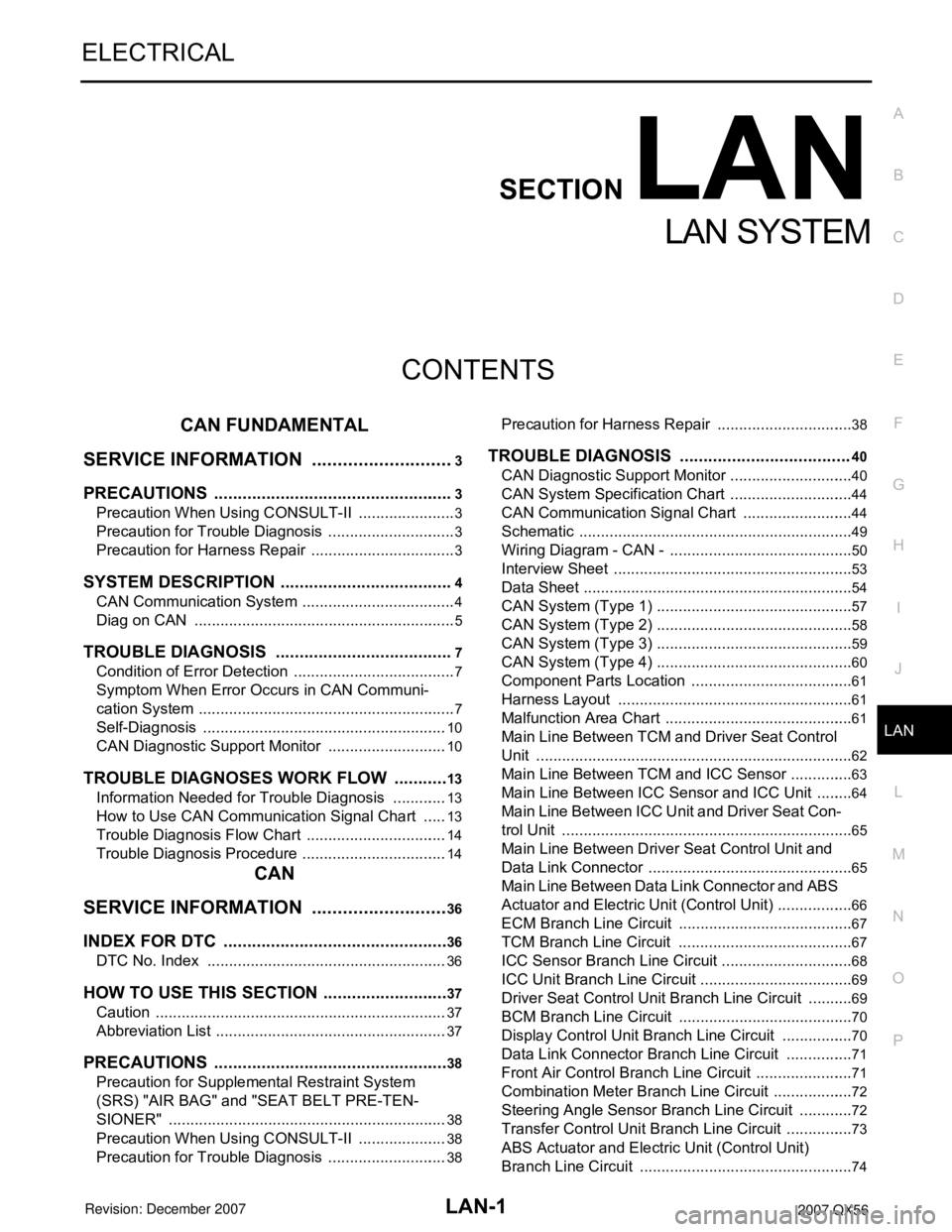
CAN FUNDAMENTAL
SERVICE INFORMATION ............................
3
PRECAUTIONS ...................................................3
Precaution When Using CONSULT-II .......................3
Precaution for Trouble Diagnosis ..............................3
Precaution for Harness Repair ..................................3
SYSTEM DESCRIPTION .....................................4
CAN Communication System ....................................4
Diag on CAN .............................................................5
TROUBLE DIAGNOSIS ......................................7
Condition of Error Detection ......................................7
Symptom When Error Occurs in CAN Communi-
cation System ............................................................
7
Self-Diagnosis .........................................................10
CAN Diagnostic Support Monitor ............................10
TROUBLE DIAGNOSES WORK FLOW ............13
Information Needed for Trouble Diagnosis .............13
How to Use CAN Communication Signal Chart ......13
Trouble Diagnosis Flow Chart .................................14
Trouble Diagnosis Procedure ..................................14
CAN
SERVICE INFORMATION ...........................
36
INDEX FOR DTC ................................................36
DTC No. Index ........................................................36
HOW TO USE THIS SECTION ...........................37
Caution ....................................................................37
Abbreviation List ......................................................37
PRECAUTIONS ..................................................38
Precaution for Supplemental Restraint System
(SRS) "AIR BAG" and "SEAT BELT PRE-TEN-
SIONER" .................................................................
38
Precaution When Using CONSULT-II .....................38
Precaution for Trouble Diagnosis ............................38
Precaution for Harness Repair ................................38
TROUBLE DIAGNOSIS ....................................40
CAN Diagnostic Support Monitor .............................40
CAN System Specification Chart .............................44
CAN Communication Signal Chart ..........................44
Schematic ................................................................49
Wiring Diagram - CAN - ...........................................50
Interview Sheet ........................................................53
Data Sheet ...............................................................54
CAN System (Type 1) ..............................................57
CAN System (Type 2) ..............................................58
CAN System (Type 3) ..............................................59
CAN System (Type 4) ..............................................60
Component Parts Location ......................................61
Harness Layout .......................................................61
Malfunction Area Chart ............................................61
Main Line Between TCM and Driver Seat Control
Unit ..........................................................................
62
Main Line Between TCM and ICC Sensor ...............63
Main Line Between ICC Sensor and ICC Unit .........64
Main Line Between ICC Unit and Driver Seat Con-
trol Unit ....................................................................
65
Main Line Between Driver Seat Control Unit and
Data Link Connector ................................................
65
Main Line Between Data Link Connector and ABS
Actuator and Electric Unit (Control Unit) ..................
66
ECM Branch Line Circuit .........................................67
TCM Branch Line Circuit .........................................67
ICC Sensor Branch Line Circuit ...............................68
ICC Unit Branch Line Circuit ....................................69
Driver Seat Control Unit Branch Line Circuit ...........69
BCM Branch Line Circuit .........................................70
Display Control Unit Branch Line Circuit .................70
Data Link Connector Branch Line Circuit ................71
Front Air Control Branch Line Circuit .......................71
Combination Meter Branch Line Circuit ...................72
Steering Angle Sensor Branch Line Circuit .............72
Transfer Control Unit Branch Line Circuit ................73
ABS Actuator and Electric Unit (Control Unit)
Branch Line Circuit ..................................................
74
Page 2181 of 3061
![INFINITI QX56 2007 Factory Service Manual LAN-50
< SERVICE INFORMATION >[CAN]
TROUBLE DIAGNOSIS
Wiring Diagram - CAN -
INFOID:0000000003533630
BKWA0731E INFINITI QX56 2007 Factory Service Manual LAN-50
< SERVICE INFORMATION >[CAN]
TROUBLE DIAGNOSIS
Wiring Diagram - CAN -
INFOID:0000000003533630
BKWA0731E](/manual-img/42/57029/w960_57029-2180.png)
LAN-50
< SERVICE INFORMATION >[CAN]
TROUBLE DIAGNOSIS
Wiring Diagram - CAN -
INFOID:0000000003533630
BKWA0731E
Page 2203 of 3061
![INFINITI QX56 2007 Factory Service Manual LAN-72
< SERVICE INFORMATION >[CAN]
TROUBLE DIAGNOSIS
2.CHECK HARNESS FOR OPEN CIRCUIT
1. Disconnect the connector of front air control.
2. Check the resistance between the front air control harness c INFINITI QX56 2007 Factory Service Manual LAN-72
< SERVICE INFORMATION >[CAN]
TROUBLE DIAGNOSIS
2.CHECK HARNESS FOR OPEN CIRCUIT
1. Disconnect the connector of front air control.
2. Check the resistance between the front air control harness c](/manual-img/42/57029/w960_57029-2202.png)
LAN-72
< SERVICE INFORMATION >[CAN]
TROUBLE DIAGNOSIS
2.CHECK HARNESS FOR OPEN CIRCUIT
1. Disconnect the connector of front air control.
2. Check the resistance between the front air control harness connector terminals.
OK or NG
OK >> GO TO 3.
NG >> Repair the front air control branch line.
3.CHECK POWER SUPPLY AND GROUND CIRCUIT
Check the power supply and the ground circuit of the front air control. Refer to ATC-36, "
Schematic".
OK or NG
OK >> • Present error: Replace the front air control. Refer to ATC-123, "Removal and Installation".
• Past error: Error was detected in the front air control branch line.
NG >> Repair the power supply and the ground circuit.
Combination Meter Branch Line CircuitINFOID:0000000003533655
INSPECTION PROCEDURE
1.CHECK CONNECTOR
1. Turn the ignition switch OFF.
2. Disconnect the battery cable from the negative terminal.
3. Check the terminals and connectors of the combination meter for damage, bend and loose connection
(unit side and connector side).
OK or NG
OK >> GO TO 2.
NG >> Repair the terminal and connector.
2.CHECK HARNESS FOR OPEN CIRCUIT
1. Disconnect the connector of combination meter.
2. Check the resistance between the combination meter harness connector terminals.
OK or NG
OK >> GO TO 3.
NG >> Repair the combination meter branch line.
3.CHECK POWER SUPPLY AND GROUND CIRCUIT
Check the power supply and the ground circuit of the combination meter. Refer to DI-9, "
Wiring Diagram -
METER -".
OK or NG
OK >> • Present error: Replace the combination meter. Refer to IP-10, "Removal and Installation".
• Past error: Error was detected in the combination meter branch line.
NG >> Repair the power supply and the ground circuit.
Steering Angle Sensor Branch Line CircuitINFOID:0000000003533656
INSPECTION PROCEDURE
1.CHECK CONNECTOR
1. Turn the ignition switch OFF.
Front air control harness connector
Resistance (Ω)
Connector No. Terminal No.
M50 34 35 Approx. 54 – 66
Combination meter harness connector
Resistance (Ω)
Connector No. Terminal No.
M24 11 12 Approx. 54 – 66
Page 2208 of 3061
LT-1
ELECTRICAL
C
D
E
F
G
H
I
J
L
M
SECTION LT
A
B
LT
N
O
P
CONTENTS
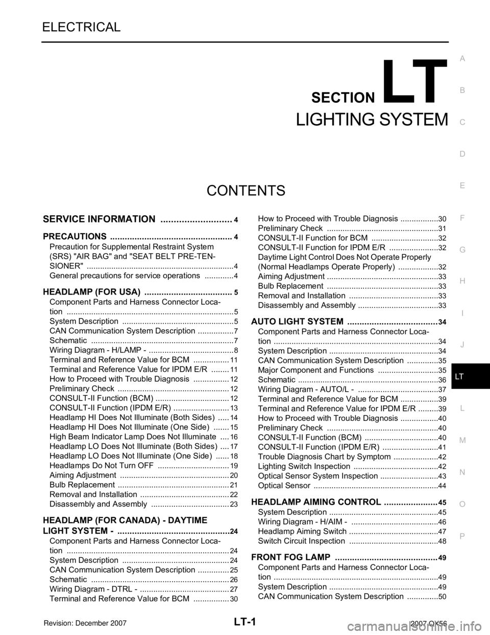
LIGHTING SYSTEM
SERVICE INFORMATION ............................4
PRECAUTIONS ...................................................4
Precaution for Supplemental Restraint System
(SRS) "AIR BAG" and "SEAT BELT PRE-TEN-
SIONER" ...................................................................
4
General precautions for service operations ..............4
HEADLAMP (FOR USA) .....................................5
Component Parts and Harness Connector Loca-
tion ............................................................................
5
System Description ...................................................5
CAN Communication System Description .................7
Schematic .................................................................7
Wiring Diagram - H/LAMP - .......................................8
Terminal and Reference Value for BCM .................11
Terminal and Reference Value for IPDM E/R .........11
How to Proceed with Trouble Diagnosis .................12
Preliminary Check ...................................................12
CONSULT-II Function (BCM) ..................................12
CONSULT-II Function (IPDM E/R) ..........................13
Headlamp HI Does Not Illuminate (Both Sides) ......14
Headlamp HI Does Not Illuminate (One Side) ........15
High Beam Indicator Lamp Does Not Illuminate .....16
Headlamp LO Does Not Illuminate (Both Sides) .....17
Headlamp LO Does Not Illuminate (One Side) .......18
Headlamps Do Not Turn OFF .................................19
Aiming Adjustment ..................................................20
Bulb Replacement ...................................................21
Removal and Installation .........................................22
Disassembly and Assembly ....................................23
HEADLAMP (FOR CANADA) - DAYTIME
LIGHT SYSTEM - ...............................................
24
Component Parts and Harness Connector Loca-
tion ..........................................................................
24
System Description .................................................24
CAN Communication System Description ...............25
Schematic ...............................................................26
Wiring Diagram - DTRL - .........................................27
Terminal and Reference Value for BCM .................30
How to Proceed with Trouble Diagnosis ..................30
Preliminary Check ...................................................31
CONSULT-II Function for BCM ...............................32
CONSULT-II Function for IPDM E/R .......................32
Daytime Light Control Does Not Operate Properly
(Normal Headlamps Operate Properly) ...................
32
Aiming Adjustment ...................................................33
Bulb Replacement ...................................................33
Removal and Installation .........................................33
Disassembly and Assembly .....................................33
AUTO LIGHT SYSTEM .....................................34
Component Parts and Harness Connector Loca-
tion ...........................................................................
34
System Description ..................................................34
CAN Communication System Description ...............35
Major Component and Functions ............................35
Schematic ................................................................36
Wiring Diagram - AUTO/L - .....................................37
Terminal and Reference Value for BCM ..................39
Terminal and Reference Value for IPDM E/R ..........39
How to Proceed with Trouble Diagnosis ..................40
Preliminary Check ...................................................40
CONSULT-II Function (BCM) ..................................40
CONSULT-II Function (IPDM E/R) ..........................41
Trouble Diagnosis Chart by Symptom .....................42
Lighting Switch Inspection .......................................42
Optical Sensor System Inspection ...........................43
Optical Sensor .........................................................44
HEADLAMP AIMING CONTROL ......................45
System Description ..................................................45
Wiring Diagram - H/AIM - ........................................46
Headlamp Aiming Switch .........................................47
Switch Circuit Inspection .........................................48
FRONT FOG LAMP ..........................................49
Component Parts and Harness Connector Loca-
tion ...........................................................................
49
System Description ..................................................49
CAN Communication System Description ...............50
Page 2209 of 3061
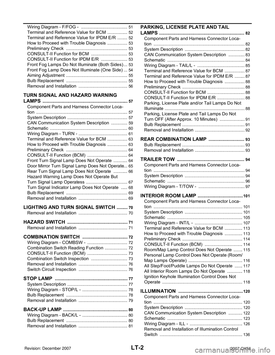
LT-2
Wiring Diagram - F/FOG - ......................................51
Terminal and Reference Value for BCM .................52
Terminal and Reference Value for IPDM E/R .........52
How to Proceed with Trouble Diagnosis .................53
Preliminary Check ..................................................53
CONSULT-II Function for BCM ..............................53
CONSULT-II Function for IPDM E/R ......................53
Front Fog Lamps Do Not Illuminate (Both Sides) ...53
Front Fog Lamp Does Not Illuminate (One Side) ...54
Aiming Adjustment ..................................................55
Bulb Replacement ..................................................55
Removal and Installation ........................................56
TURN SIGNAL AND HAZARD WARNING
LAMPS ...............................................................
57
Component Parts and Harness Connector Loca-
tion ..........................................................................
57
System Description .................................................57
CAN Communication System Description ..............59
Schematic ...............................................................60
Wiring Diagram - TURN - ........................................61
Terminal and Reference Value for BCM .................63
How to Proceed with Trouble Diagnosis .................63
Preliminary Check ..................................................64
CONSULT-II Function (BCM) .................................64
Front Turn Signal Lamp Does Not Operate ............64
Door Mirror Turn Signal Lamp Does Not Operate ...65
Rear Turn Signal Lamp Does Not Operate ............66
Hazard Warning Lamp Does Not Operate But
Turn Signal Lamp Operatess ..................................
67
Turn Signal Indicator Lamp Does Not Operate ......68
Bulb Replacement ..................................................69
Removal and Installation ........................................69
LIGHTING AND TURN SIGNAL SWITCH .........70
Removal and Installation ........................................70
HAZARD SWITCH .............................................71
Removal and Installation ........................................71
COMBINATION SWITCH ..................................72
Wiring Diagram - COMBSW - .................................72
Combination Switch Reading Function ...................72
CONSULT-II Function (BCM) .................................73
Combination Switch Inspection ..............................73
Removal and Installation ........................................76
Switch Circuit Inspection ........................................76
STOP LAMP ......................................................77
System Description .................................................77
Wiring Diagram - STOP/L - .....................................78
Bulb Replacement ..................................................78
Removal and Installation ........................................79
BACK-UP LAMP ................................................80
Wiring Diagram - BACK/L - .....................................80
Bulb Replacement ..................................................80
Removal and Installation ........................................81
PARKING, LICENSE PLATE AND TAIL
LAMPS ...............................................................
82
Component Parts and Harness Connector Loca-
tion ..........................................................................
82
System Description .................................................82
CAN Communication System Description ..............83
Schematic ...............................................................84
Wiring Diagram - TAIL/L - .......................................85
Terminal and Reference Value for BCM .................87
Terminal and Reference Value for IPDM E/R .........87
How to Proceed with Trouble Diagnosis .................88
Preliminary Check ...................................................88
CONSULT-II Function for BCM ...............................88
CONSULT-II Function for IPDM E/R .......................88
Parking, License Plate and/or Tail Lamps Do Not
Illuminate .................................................................
88
Parking, License Plate and Tail Lamps Do Not
Turn OFF (After Approx. 10 Minutes) .....................
91
Bulb Replacement ...................................................91
Removal and Installation .........................................92
REAR COMBINATION LAMP ...........................93
Bulb Replacement ...................................................93
Removal and Installation .........................................93
TRAILER TOW ..................................................94
Component Parts and Harness Connector Loca-
tion ..........................................................................
94
System Description .................................................94
Schematic ...............................................................96
Wiring Diagram - T/TOW - ......................................97
INTERIOR ROOM LAMP ..................................101
Component Parts and Harness Connector Loca-
tion ........................................................................
101
System Description ...............................................101
Schematic .............................................................105
Wiring Diagram - INT/L - .......................................107
Terminal and Reference Value for BCM ...............113
How to Proceed with Trouble Diagnosis ...............113
Preliminary Check .................................................114
CONSULT-II Function (BCM) ...............................114
Room/Map Lamp Control Does Not Operate ........115
Personal Lamp Control Does Not Operate (Room/
Map Lamps Operate) ............................................
116
All Step/Foot/Puddle Lamps Do Not Operate .......117
All Interior Room Lamps Do Not Operate .............118
Ignition Keyhole Illumination Control Does Not
Operate .................................................................
118
ILLUMINATION ................................................120
Component Parts and Harness Connector Loca-
tion ........................................................................
120
System Description ...............................................120
CAN Communication System Description ............122
Schematic .............................................................123
Wiring Diagram - ILL - ...........................................126
Removal and Installation of Illumination Control
Switch ...................................................................
136
Page 2215 of 3061
LT-8
< SERVICE INFORMATION >
HEADLAMP (FOR USA)
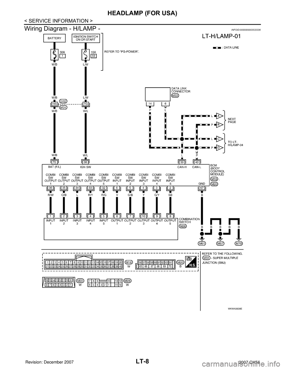
Wiring Diagram - H/LAMP -
INFOID:0000000003533336
WKWA3638E