2007 INFINITI QX56 turn signal
[x] Cancel search: turn signalPage 1415 of 3061
EC-332
< SERVICE INFORMATION >
DTC P0327, P0328, P0332, P0333 KS
DTC P0327, P0328, P0332, P0333 KS
Component DescriptionINFOID:0000000003531825
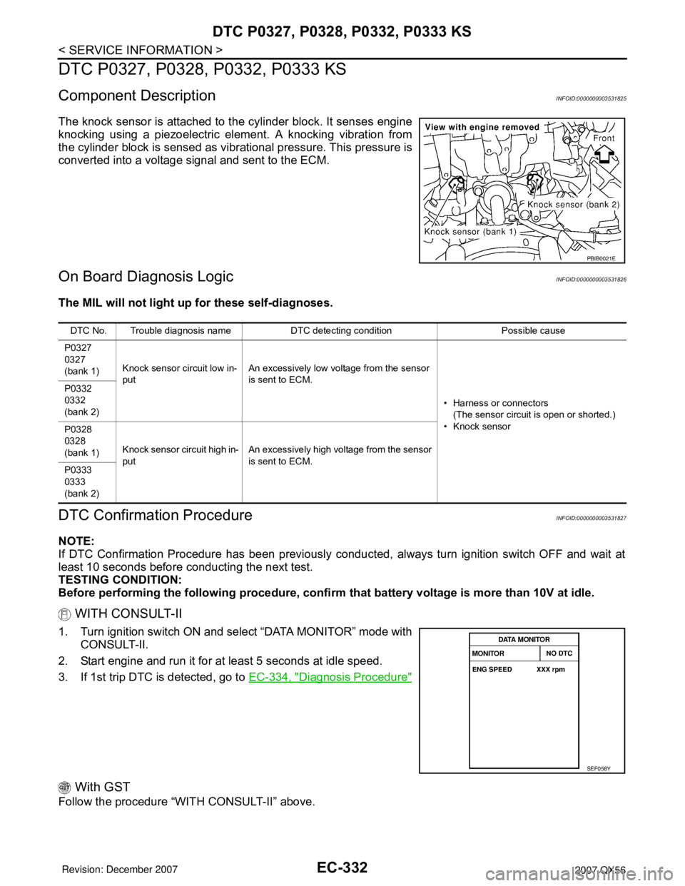
The knock sensor is attached to the cylinder block. It senses engine
knocking using a piezoelectric element. A knocking vibration from
the cylinder block is sensed as vibrational pressure. This pressure is
converted into a voltage signal and sent to the ECM.
On Board Diagnosis LogicINFOID:0000000003531826
The MIL will not light up for these self-diagnoses.
DTC Confirmation ProcedureINFOID:0000000003531827
NOTE:
If DTC Confirmation Procedure has been previously conducted, always turn ignition switch OFF and wait at
least 10 seconds before conducting the next test.
TESTING CONDITION:
Before performing the following procedure, confirm that battery voltage is more than 10V at idle.
WITH CONSULT-II
1. Turn ignition switch ON and select “DATA MONITOR” mode with
CONSULT-II.
2. Start engine and run it for at least 5 seconds at idle speed.
3. If 1st trip DTC is detected, go to EC-334, "
Diagnosis Procedure"
With GST
Follow the procedure “WITH CONSULT-II” above.
PBIB0021E
DTC No. Trouble diagnosis name DTC detecting condition Possible cause
P0327
0327
(bank 1)Knock sensor circuit low in-
putAn excessively low voltage from the sensor
is sent to ECM.
• Harness or connectors
(The sensor circuit is open or shorted.)
• Knock sensor P0332
0332
(bank 2)
P0328
0328
(bank 1)Knock sensor circuit high in-
putAn excessively high voltage from the sensor
is sent to ECM.
P0333
0333
(bank 2)
SEF058Y
Page 1417 of 3061
EC-334
< SERVICE INFORMATION >
DTC P0327, P0328, P0332, P0333 KS
Diagnosis Procedure
INFOID:0000000003531829
1.CHECK KNOCK SENSOR INPUT SIGNAL CIRCUIT FOR OPEN AND SHORT-I
1. Turn ignition switch OFF.
2. Disconnect ECM harness connector.
3. Check resistance between ECM terminals 15, 36 and ground. Refer to Wiring Diagram.
NOTE:
It is necessary to use an ohmmeter which can measure more than 10 MΩ.
4. Also check harness for short to ground and short to power.
OK or NG
OK >> GO TO 5.
NG >> GO TO 2.
2.CHECK KNOCK SENSOR INPUT SIGNAL CIRCUIT FOR OPEN AND SHORT-II
1. Disconnect knock sensor harness connector.
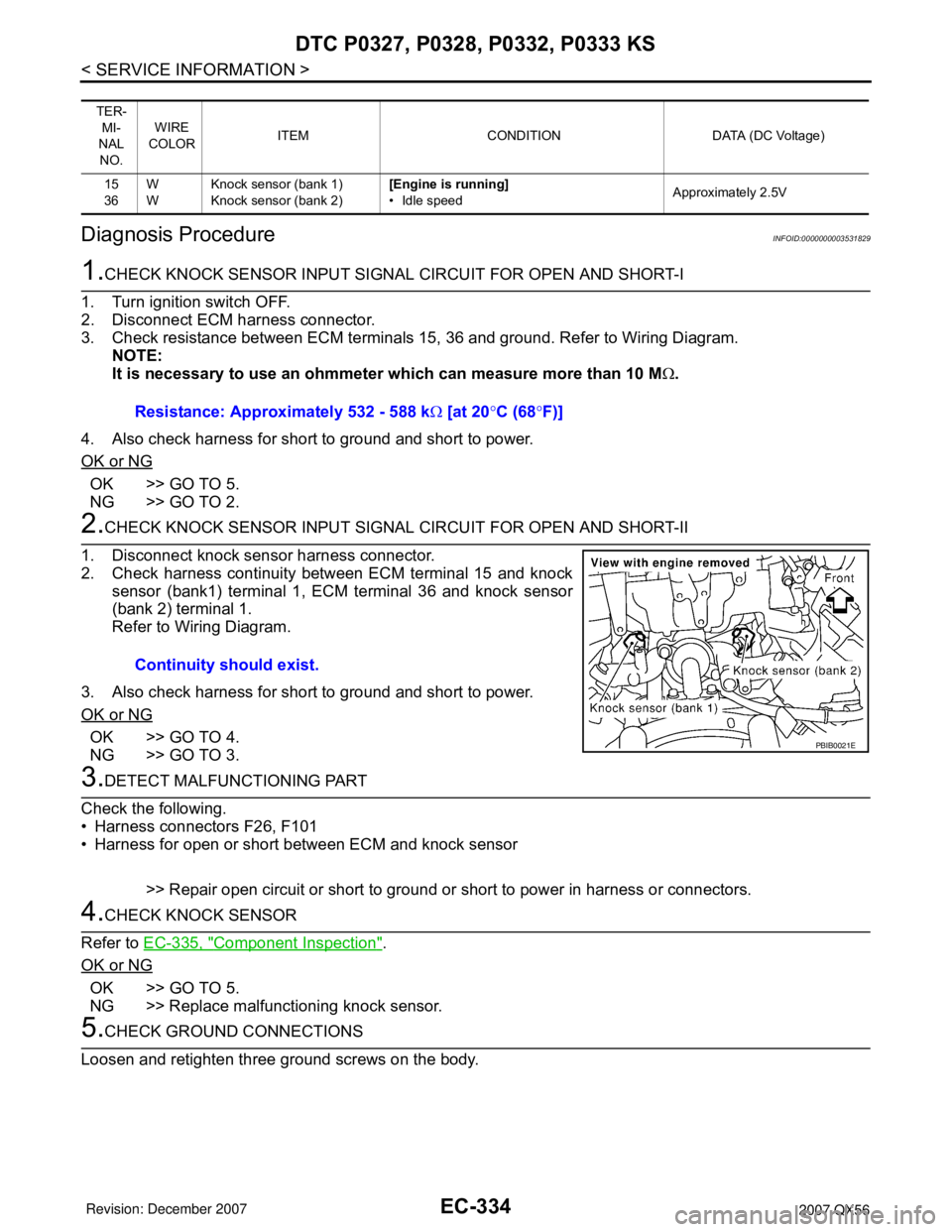
2. Check harness continuity between ECM terminal 15 and knock
sensor (bank1) terminal 1, ECM terminal 36 and knock sensor
(bank 2) terminal 1.
Refer to Wiring Diagram.
3. Also check harness for short to ground and short to power.
OK or NG
OK >> GO TO 4.
NG >> GO TO 3.
3.DETECT MALFUNCTIONING PART
Check the following.
• Harness connectors F26, F101
• Harness for open or short between ECM and knock sensor
>> Repair open circuit or short to ground or short to power in harness or connectors.
4.CHECK KNOCK SENSOR
Refer to EC-335, "
Component Inspection".
OK or NG
OK >> GO TO 5.
NG >> Replace malfunctioning knock sensor.
5.CHECK GROUND CONNECTIONS
Loosen and retighten three ground screws on the body.
TER-
MI-
NAL
NO.WIRE
COLORITEM CONDITION DATA (DC Voltage)
15
36W
WKnock sensor (bank 1)
Knock sensor (bank 2)[Engine is running]
• Idle speedApproximately 2.5V
Resistance: Approximately 532 - 588 kΩ [at 20°C (68°F)]
Continuity should exist.
PBIB0021E
Page 1419 of 3061
EC-336
< SERVICE INFORMATION >
DTC P0335 CKP SENSOR (POS)
DTC P0335 CKP SENSOR (POS)
Component DescriptionINFOID:0000000003531832
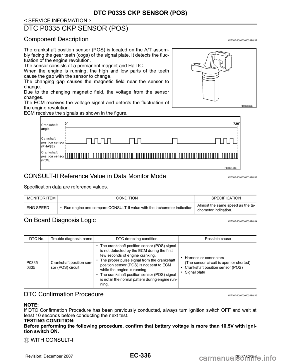
The crankshaft position sensor (POS) is located on the A/T assem-
bly facing the gear teeth (cogs) of the signal plate. It detects the fluc-
tuation of the engine revolution.
The sensor consists of a permanent magnet and Hall IC.
When the engine is running, the high and low parts of the teeth
cause the gap with the sensor to change.
The changing gap causes the magnetic field near the sensor to
change.
Due to the changing magnetic field, the voltage from the sensor
changes.
The ECM receives the voltage signal and detects the fluctuation of
the engine revolution.
ECM receives the signals as shown in the figure.
CONSULT-II Reference Value in Data Monitor ModeINFOID:0000000003531833
Specification data are reference values.
On Board Diagnosis LogicINFOID:0000000003531834
DTC Confirmation ProcedureINFOID:0000000003531835
NOTE:
If DTC Confirmation Procedure has been previously conducted, always turn ignition switch OFF and wait at
least 10 seconds before conducting the next test.
TESTING CONDITION:
Before performing the following procedure, confirm that battery voltage is more than 10.5V with igni-
tion switch ON.
WITH CONSULT-II
PBIB0562E
PBIB2448E
MONITOR ITEM CONDITION SPECIFICATION
ENG SPEED • Run engine and compare CONSULT-II value with the tachometer indication.Almost the same speed as the ta-
chometer indication.
DTC No. Trouble diagnosis name DTC detecting condition Possible cause
P0335
0335Crankshaft position sen-
sor (POS) circuit• The crankshaft position sensor (POS) signal
is not detected by the ECM during the first
few seconds of engine cranking.
• The proper pulse signal from the crankshaft
position sensor (POS) is not sent to ECM
while the engine is running.
• The crankshaft position sensor (POS) signal
is not in the normal pattern during engine run-
ning.• Harness or connectors
(The sensor circuit is open or shorted)
• Crankshaft position sensor (POS)
• Signal plate
Page 1422 of 3061
DTC P0335 CKP SENSOR (POS)
EC-339
< SERVICE INFORMATION >
C
D
E
F
G
H
I
J
K
L
MA
EC
N
P O
Do not use ECM ground terminals when measuring input/output voltage. Doing so may result in dam-
age to the ECM's transistor. Use a ground other than ECM terminals, such as the ground.
: Average voltage for pulse signal (Actual pulse signal can be confirmed by oscilloscope.)
Diagnosis ProcedureINFOID:0000000003531837
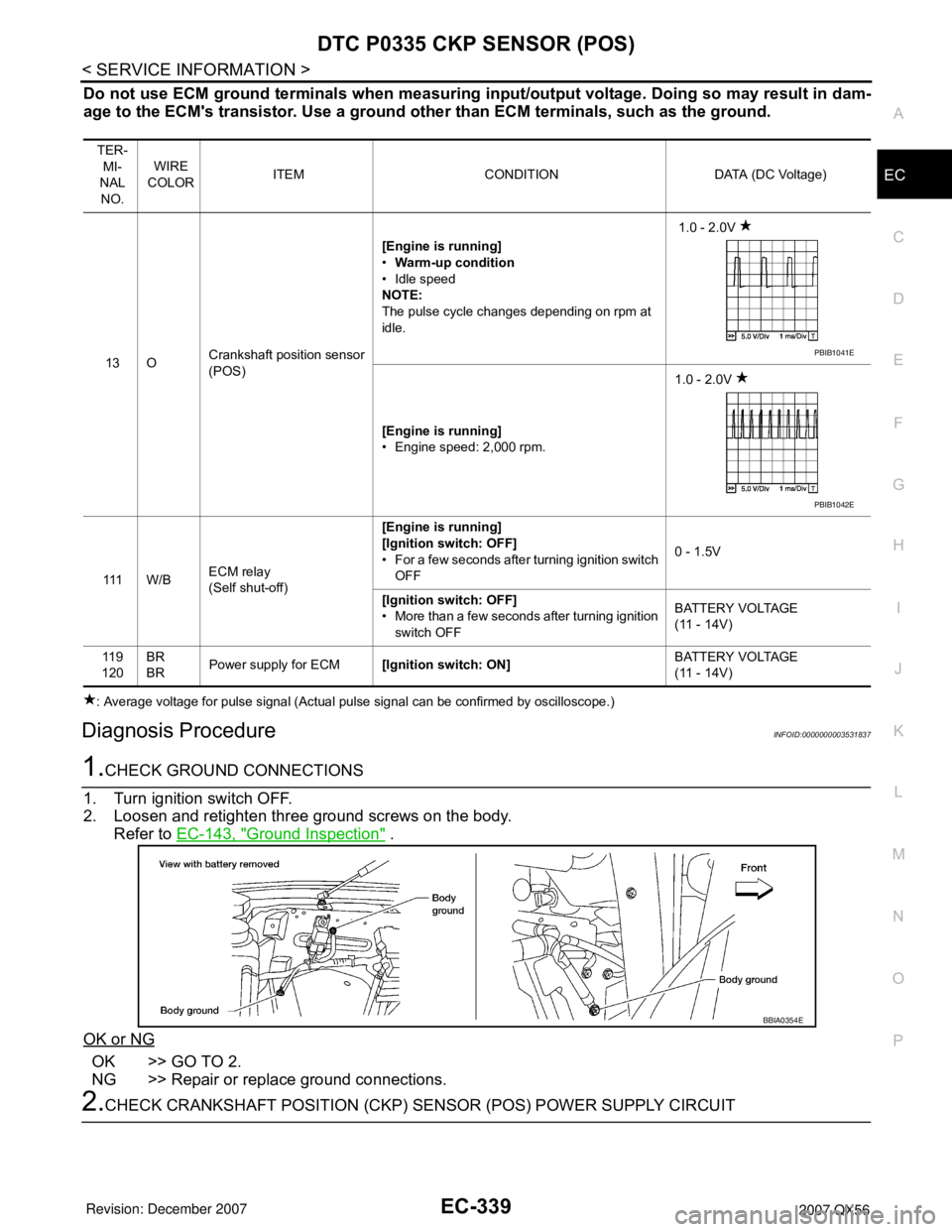
1.CHECK GROUND CONNECTIONS
1. Turn ignition switch OFF.
2. Loosen and retighten three ground screws on the body.
Refer to EC-143, "
Ground Inspection" .
OK or NG
OK >> GO TO 2.
NG >> Repair or replace ground connections.
2.CHECK CRANKSHAFT POSITION (CKP) SENSOR (POS) POWER SUPPLY CIRCUIT
TER-
MI-
NAL
NO.WIRE
COLORITEM CONDITION DATA (DC Voltage)
13 OCrankshaft position sensor
(POS)[Engine is running]
•Warm-up condition
• Idle speed
NOTE:
The pulse cycle changes depending on rpm at
idle. 1.0 - 2.0V
[Engine is running]
• Engine speed: 2,000 rpm.1.0 - 2.0V
111 W / BECM relay
(Self shut-off)[Engine is running]
[Ignition switch: OFF]
• For a few seconds after turning ignition switch
OFF0 - 1.5V
[Ignition switch: OFF]
• More than a few seconds after turning ignition
switch OFFBATTERY VOLTAGE
(11 - 14V)
11 9
120BR
BRPower supply for ECM[Ignition switch: ON]BATTERY VOLTAGE
(11 - 14V)
PBIB1041E
PBIB1042E
BBIA0354E
Page 1423 of 3061

EC-340
< SERVICE INFORMATION >
DTC P0335 CKP SENSOR (POS)
1. Disconnect crankshaft position (CKP) sensor (POS) harness
connector.
2. Turn ignition switch ON.
3. Check voltage between CKP sensor (POS) terminal 3 and
ground with CONSULT-II or tester.
OK or NG
OK >> GO TO 4.
NG >> GO TO 3.
3.DETECT MALFUNCTIONING PART
Check the following.
• Harness connectors F32, E2
• Harness for open or short between crankshaft position sensor (POS) and ECM
• Harness for open or short between crankshaft position sensor (POS) and IPDM E/R
>> Repair open circuit or short to ground or short to power in harness or connectors.
4.CHECK CKP SENSOR (POS) GROUND CIRCUIT FOR OPEN AND SHORT
1. Turn ignition switch OFF.
2. Check harness continuity between CKP sensor (POS) terminal 1 and ground.
Refer to Wiring Diagram.
3. Also check harness for short to power.
OK or NG
OK >> GO TO 6.
NG >> GO TO 5.
5.DETECT MALFUNCTIONING PART
Check the following.
• Harness connectors F32, E2
• Harness for open or short between crankshaft position sensor (POS) and ground
>> Repair open circuit or short to power in harness or connectors.
6.CHECK CKP SENSOR (POS) INPUT SIGNAL CIRCUIT FOR OPEN AND SHORT
1. Disconnect ECM harness connector.
2. Check harness continuity between ECM terminal 13 and CKP sensor (POS) terminal 2.
Refer to Wiring Diagram.
3. Also check harness for short to ground and short to power.
BBIA0367E
Voltage: Battery voltage
SEF481Y
Continuity should exist.
Continuity should exist.
Page 1425 of 3061
EC-342
< SERVICE INFORMATION >
DTC P0340 CMP SENSOR (PHASE)
DTC P0340 CMP SENSOR (PHASE)
Component DescriptionINFOID:0000000003531840
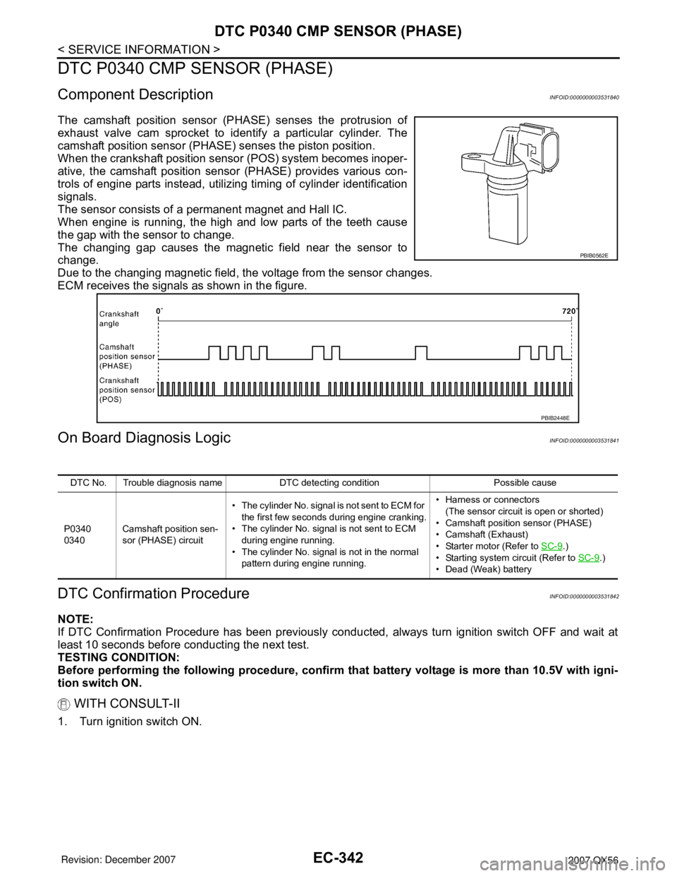
The camshaft position sensor (PHASE) senses the protrusion of
exhaust valve cam sprocket to identify a particular cylinder. The
camshaft position sensor (PHASE) senses the piston position.
When the crankshaft position sensor (POS) system becomes inoper-
ative, the camshaft position sensor (PHASE) provides various con-
trols of engine parts instead, utilizing timing of cylinder identification
signals.
The sensor consists of a permanent magnet and Hall IC.
When engine is running, the high and low parts of the teeth cause
the gap with the sensor to change.
The changing gap causes the magnetic field near the sensor to
change.
Due to the changing magnetic field, the voltage from the sensor changes.
ECM receives the signals as shown in the figure.
On Board Diagnosis LogicINFOID:0000000003531841
DTC Confirmation ProcedureINFOID:0000000003531842
NOTE:
If DTC Confirmation Procedure has been previously conducted, always turn ignition switch OFF and wait at
least 10 seconds before conducting the next test.
TESTING CONDITION:
Before performing the following procedure, confirm that battery voltage is more than 10.5V with igni-
tion switch ON.
WITH CONSULT-II
1. Turn ignition switch ON.
PBIB0562E
PBIB2448E
DTC No. Trouble diagnosis name DTC detecting condition Possible cause
P0340
0340Camshaft position sen-
sor (PHASE) circuit• The cylinder No. signal is not sent to ECM for
the first few seconds during engine cranking.
• The cylinder No. signal is not sent to ECM
during engine running.
• The cylinder No. signal is not in the normal
pattern during engine running.• Harness or connectors
(The sensor circuit is open or shorted)
• Camshaft position sensor (PHASE)
• Camshaft (Exhaust)
• Starter motor (Refer to SC-9
.)
• Starting system circuit (Refer to SC-9
.)
• Dead (Weak) battery
Page 1428 of 3061
DTC P0340 CMP SENSOR (PHASE)
EC-345
< SERVICE INFORMATION >
C
D
E
F
G
H
I
J
K
L
MA
EC
N
P O
Do not use ECM ground terminals when measuring input/output voltage. Doing so may result in dam-
age to the ECM's transistor. Use a ground other than ECM terminals, such as the ground.
: Average voltage for pulse signal (Actual pulse signal can be confirmed by oscilloscope.)
Diagnosis ProcedureINFOID:0000000003531844
1.CHECK STARTING SYSTEM
Turn ignition switch to START position.
Ye s o r N o
Yes >> GO TO 2.
No >> Check starting system. (Refer to SC-9
.)
2.CHECK GROUND CONNECTIONS
1. Turn ignition switch OFF.
2. Loosen and retighten three ground screws on the body.
TER-
MI-
NAL
NO.WIRE
COLORITEM CONDITION DATA (DC Voltage)
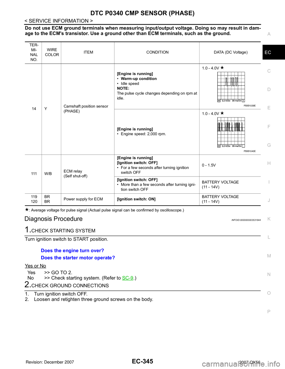
14 YCamshaft position sensor
(PHASE)[Engine is running]
•Warm-up condition
• Idle speed
NOTE:
The pulse cycle changes depending on rpm at
idle.1.0 - 4.0V
[Engine is running]
• Engine speed: 2,000 rpm.1.0 - 4.0V
111 W / BECM relay
(Self shut-off)[Engine is running]
[Ignition switch: OFF]
• For a few seconds after turning ignition
switch OFF0 - 1.5V
[Ignition switch: OFF]
• More than a few seconds after turning igni-
tion switch OFFBATTERY VOLTAGE
(11 - 14V)
11 9
120BR
BRPower supply for ECM[Ignition switch: ON]BATTERY VOLTAGE
(11 - 14V)
PBIB1039E
PBIB1040E
Does the engine turn over?
Does the starter motor operate?
Page 1433 of 3061
EC-350
< SERVICE INFORMATION >
DTC P0420, P0430 THREE WAY CATALYST FUNCTION
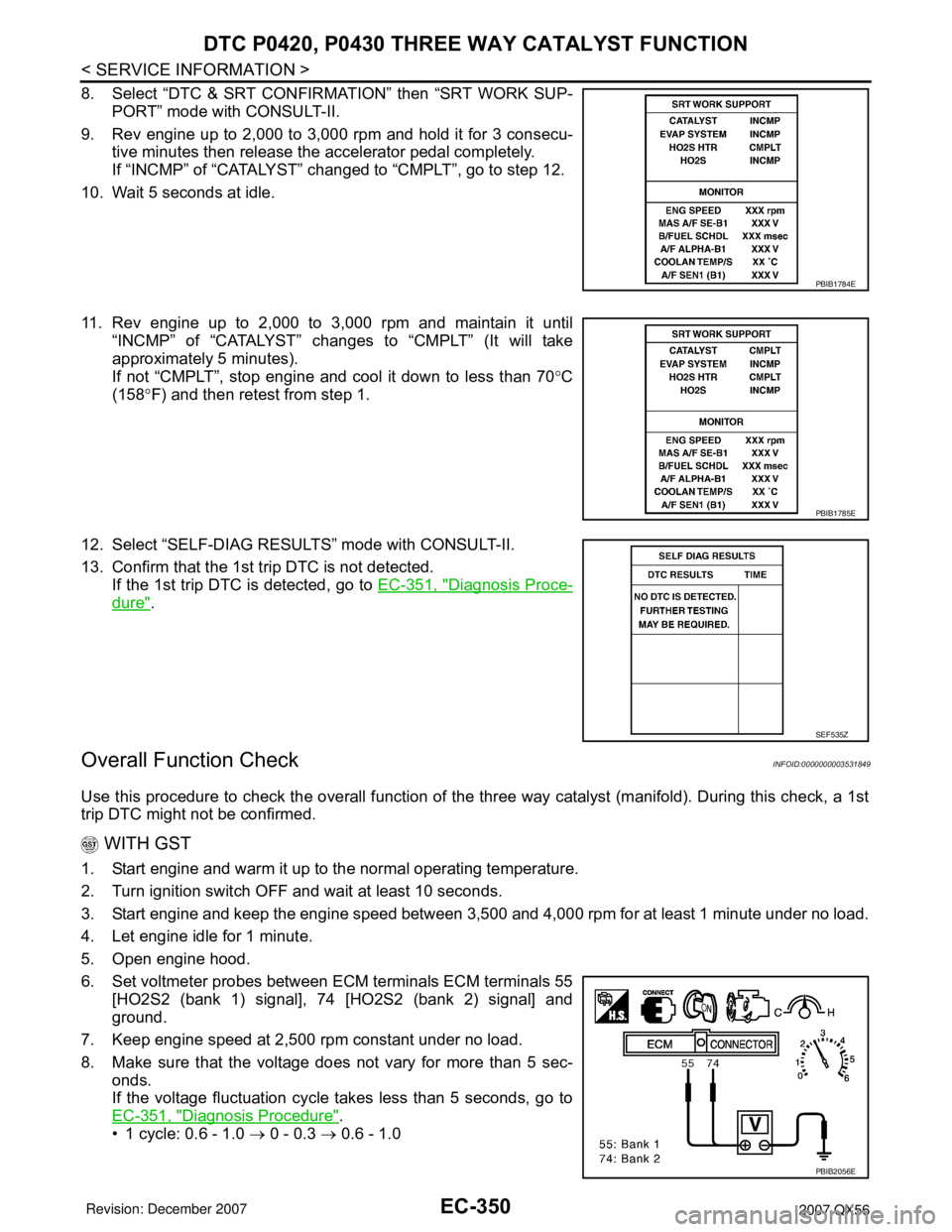
8. Select “DTC & SRT CONFIRMATION” then “SRT WORK SUP-
PORT” mode with CONSULT-II.
9. Rev engine up to 2,000 to 3,000 rpm and hold it for 3 consecu-
tive minutes then release the accelerator pedal completely.
If “INCMP” of “CATALYST” changed to “CMPLT”, go to step 12.
10. Wait 5 seconds at idle.
11. Rev engine up to 2,000 to 3,000 rpm and maintain it until
“INCMP” of “CATALYST” changes to “CMPLT” (It will take
approximately 5 minutes).
If not “CMPLT”, stop engine and cool it down to less than 70°C
(158°F) and then retest from step 1.
12. Select “SELF-DIAG RESULTS” mode with CONSULT-II.
13. Confirm that the 1st trip DTC is not detected.
If the 1st trip DTC is detected, go to EC-351, "
Diagnosis Proce-
dure".
Overall Function CheckINFOID:0000000003531849
Use this procedure to check the overall function of the three way catalyst (manifold). During this check, a 1st
trip DTC might not be confirmed.
WITH GST
1. Start engine and warm it up to the normal operating temperature.
2. Turn ignition switch OFF and wait at least 10 seconds.
3. Start engine and keep the engine speed between 3,500 and 4,000 rpm for at least 1 minute under no load.
4. Let engine idle for 1 minute.
5. Open engine hood.
6. Set voltmeter probes between ECM terminals ECM terminals 55
[HO2S2 (bank 1) signal], 74 [HO2S2 (bank 2) signal] and
ground.
7. Keep engine speed at 2,500 rpm constant under no load.
8. Make sure that the voltage does not vary for more than 5 sec-
onds.
If the voltage fluctuation cycle takes less than 5 seconds, go to
EC-351, "
Diagnosis Procedure".
• 1 cycle: 0.6 - 1.0 → 0 - 0.3 → 0.6 - 1.0
PBIB1784E
PBIB1785E
SEF535Z
PBIB2056E