Page 1559 of 3061

EC-476
< SERVICE INFORMATION >
DTC P1217 ENGINE OVER TEMPERATURE
Main 13 Causes of Overheating
INFOID:0000000003531995
*1: Turn the ignition switch ON.
*2: Engine running at 3,000 rpm for 10 minutes.
*3: Drive at 90 km/h (55 MPH) for 30 minutes and then let idle for 10 minutes.
*4: After 60 minutes of cool down time.
For more information, refer to CO-6
.
Component InspectionINFOID:0000000003531996
COOLING FAN MOTOR
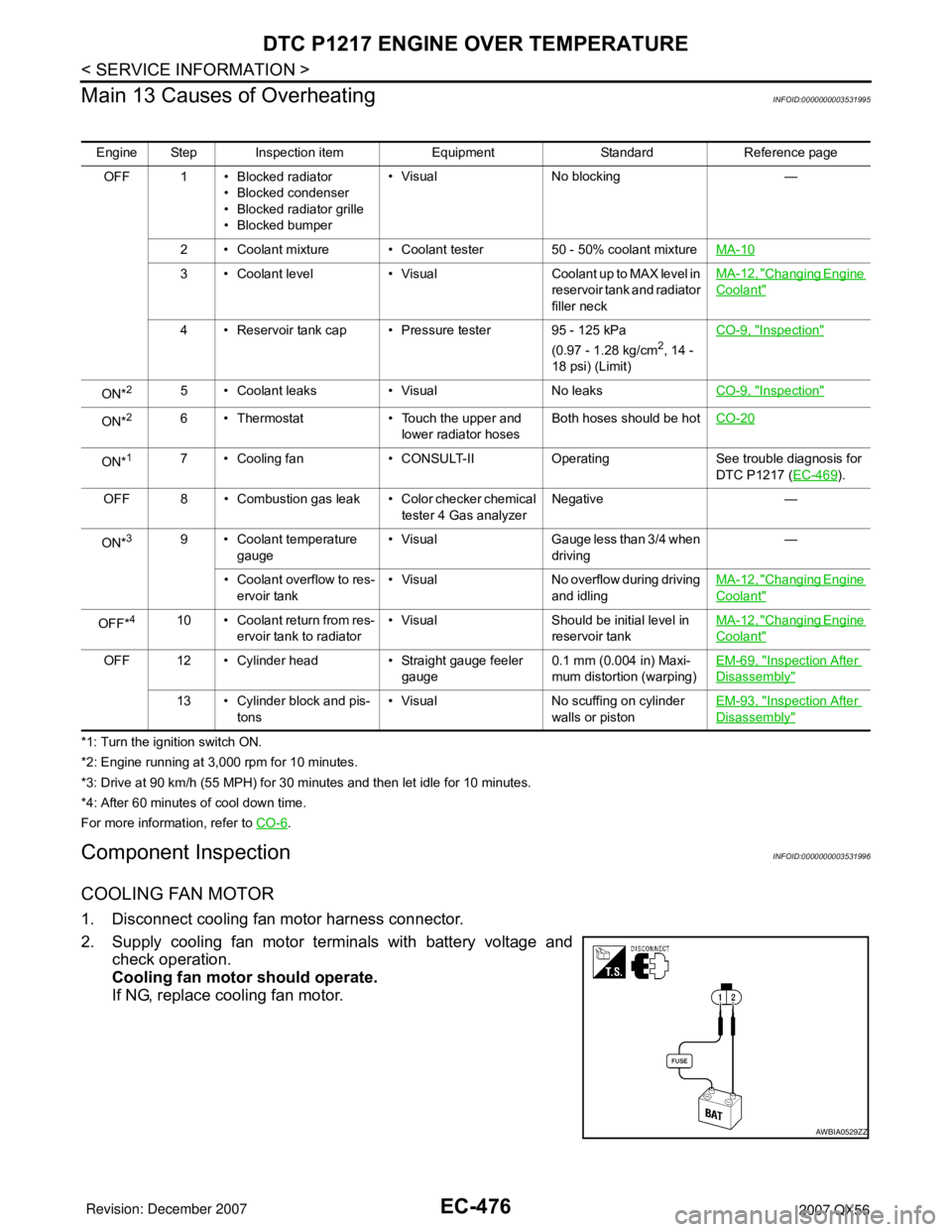
1. Disconnect cooling fan motor harness connector.
2. Supply cooling fan motor terminals with battery voltage and
check operation.
Cooling fan motor should operate.
If NG, replace cooling fan motor.
Engine Step Inspection item Equipment Standard Reference page
OFF 1 • Blocked radiator
• Blocked condenser
• Blocked radiator grille
• Blocked bumper• Visual No blocking —
2 • Coolant mixture • Coolant tester 50 - 50% coolant mixtureMA-10
3 • Coolant level • Visual Coolant up to MAX level in
reservoir tank and radiator
filler neckMA-12, "Changing Engine
Coolant"
4 • Reservoir tank cap • Pressure tester 95 - 125 kPa
(0.97 - 1.28 kg/cm2, 14 -
18 psi) (Limit)CO-9, "
Inspection"
ON*25 • Coolant leaks • Visual No leaksCO-9, "Inspection"
ON*26 • Thermostat • Touch the upper and
lower radiator hosesBoth hoses should be hotCO-20
ON*17 • Cooling fan • CONSULT-II Operating See trouble diagnosis for
DTC P1217 (EC-469
).
OFF 8 • Combustion gas leak • Color checker chemical
tester 4 Gas analyzerNegative —
ON*
39 • Coolant temperature
gauge• Visual Gauge less than 3/4 when
driving—
• Coolant overflow to res-
ervoir tank• Visual No overflow during driving
and idlingMA-12, "
Changing Engine
Coolant"
OFF*410 • Coolant return from res-
ervoir tank to radiator• Visual Should be initial level in
reservoir tankMA-12, "Changing Engine
Coolant"
OFF 12 • Cylinder head • Straight gauge feeler
gauge0.1 mm (0.004 in) Maxi-
mum distortion (warping)EM-69, "Inspection After
Disassembly"
13 • Cylinder block and pis-
tons• Visual No scuffing on cylinder
walls or pistonEM-93, "Inspection After
Disassembly"
AWBIA0529ZZ
Page 1564 of 3061

DTC P1421 COLD START CONTROL
EC-481
< SERVICE INFORMATION >
C
D
E
F
G
H
I
J
K
L
MA
EC
N
P O
DTC P1421 COLD START CONTROL
DescriptionINFOID:0000000003532007
ECM controls ignition timing and engine idle speed when engine is started with prewarming up condition.
This control promotes the activation of three way catalyst by heating the catalyst and reduces emissions.
On Board Diagnosis LogicINFOID:0000000003532008
DTC Confirmation ProcedureINFOID:0000000003532009
NOTE:
• If DTC Confirmation Procedure has been previously conducted, always turn ignition switch OFF and wait at
least 10 seconds before conducting the next test.
•If DTC P1421 is displayed with other DTC, first perform the trouble diagnosis for other DTC.
TESTING CONDITION:
Before performing the following procedure, confirm that battery voltage is more than 11V at idle.
WITH CONSULT-II
1. Turn ignition switch OFF and wait at least 10 seconds.
2. Turn ignition switch ON.
3. Select “DATA MONITOR” mode with CONSULT-II.
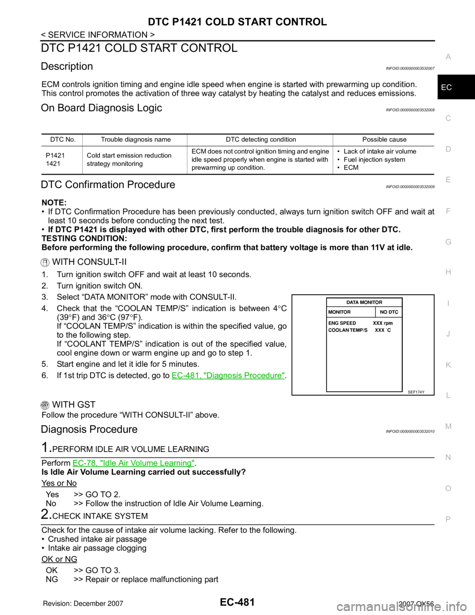
4. Check that the “COOLAN TEMP/S” indication is between 4°C
(39°F) and 36°C (97°F).
If “COOLAN TEMP/S” indication is within the specified value, go
to the following step.
If “COOLANT TEMP/S” indication is out of the specified value,
cool engine down or warm engine up and go to step 1.
5. Start engine and let it idle for 5 minutes.
6. If 1st trip DTC is detected, go to EC-481, "
Diagnosis Procedure".
WITH GST
Follow the procedure “WITH CONSULT-II” above.
Diagnosis ProcedureINFOID:0000000003532010
1.PERFORM IDLE AIR VOLUME LEARNING
Perform EC-78, "
Idle Air Volume Learning".
Is Idle Air Volume Learning carried out successfully?
Ye s o r N o
Yes >> GO TO 2.
No >> Follow the instruction of Idle Air Volume Learning.
2.CHECK INTAKE SYSTEM
Check for the cause of intake air volume lacking. Refer to the following.
• Crushed intake air passage
• Intake air passage clogging
OK or NG
OK >> GO TO 3.
NG >> Repair or replace malfunctioning part
DTC No. Trouble diagnosis name DTC detecting condition Possible cause
P1421
1421Cold start emission reduction
strategy monitoringECM does not control ignition timing and engine
idle speed properly when engine is started with
prewarming up condition.• Lack of intake air volume
• Fuel injection system
•ECM
SEF174Y
Page 1993 of 3061

SERVICE INFORMATION FOR ELECTRICAL INCIDENT
GI-27
< SERVICE INFORMATION >
C
D
E
F
G
H
I
J
K
L
MB
GI
N
O
P
The customer's concern may occur during hot weather or after car
has sat for a short time. In such cases you will want to check for a
heat sensitive condition.
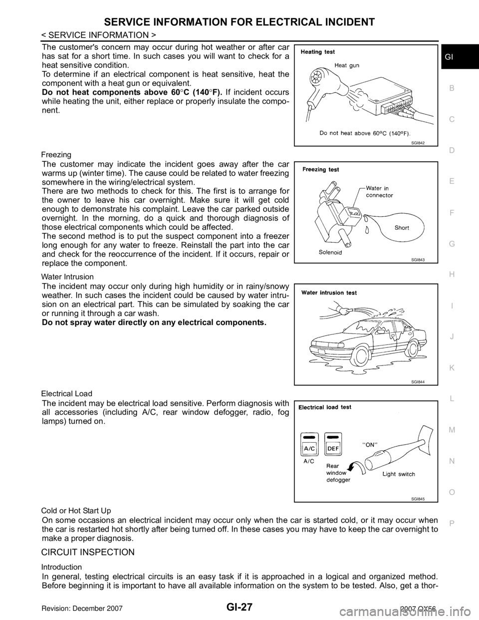
To determine if an electrical component is heat sensitive, heat the
component with a heat gun or equivalent.
Do not heat components above 60°C (140°F). If incident occurs
while heating the unit, either replace or properly insulate the compo-
nent.
Freezing
The customer may indicate the incident goes away after the car
warms up (winter time). The cause could be related to water freezing
somewhere in the wiring/electrical system.
There are two methods to check for this. The first is to arrange for
the owner to leave his car overnight. Make sure it will get cold
enough to demonstrate his complaint. Leave the car parked outside
overnight. In the morning, do a quick and thorough diagnosis of
those electrical components which could be affected.
The second method is to put the suspect component into a freezer
long enough for any water to freeze. Reinstall the part into the car
and check for the reoccurrence of the incident. If it occurs, repair or
replace the component.
Water Intrusion
The incident may occur only during high humidity or in rainy/snowy
weather. In such cases the incident could be caused by water intru-
sion on an electrical part. This can be simulated by soaking the car
or running it through a car wash.
Do not spray water directly on any electrical components.
Electrical Load
The incident may be electrical load sensitive. Perform diagnosis with
all accessories (including A/C, rear window defogger, radio, fog
lamps) turned on.
Cold or Hot Start Up
On some occasions an electrical incident may occur only when the car is started cold, or it may occur when
the car is restarted hot shortly after being turned off. In these cases you may have to keep the car overnight to
make a proper diagnosis.
CIRCUIT INSPECTION
Introduction
In general, testing electrical circuits is an easy task if it is approached in a logical and organized method.
Before beginning it is important to have all available information on the system to be tested. Also, get a thor-
SGI842
SGI843
SGI844
SGI845
Page 2748 of 3061
SE-76
< SERVICE INFORMATION >
HEATED SEAT
HEATED SEAT
DescriptionINFOID:0000000003533207
• When handling seat, be extremely careful not to scratch heating unit.
• Front passenger seat cushion and seatbacks equipped with airbags cannot be disassembled. They are
replaced as assemblies only.
• Do not use any organic solvent, such as thinner, benzene, alcohol, etc. to clean trim.
WIIA0031E
Page 2756 of 3061
SE-84
< SERVICE INFORMATION >
FRONT SEAT
Passenger Seat
7. Slide switch knob 8. Driver power seat frame assembly 9. LH outer leg cover
10. Driver seat wiring harness 11. Bolt cover 12. Seat cushion outer finisher
13. Outer pedestal finisher 14. Seat cushion front finisher 15. Seat cushion inner finisher
16. Seat cushion frame 17. Seat cushion heating element 18. Seat cushion pad
19. Seat cushion trim cover 20. Armrest assembly 21. Headrest holder
22. Seat slide/ recline switch 23. Lumbar switch
WIIA0476E
Page 2761 of 3061
SECOND SEAT
SE-89
< SERVICE INFORMATION >
C
D
E
F
G
H
J
K
L
MA
B
SE
N
O
P
SECOND SEAT
Removal and InstallationINFOID:0000000003533212
Second Row Outboard
Removal
1. Remove seat base trim cover.
2. Lift handle and tilt seat forward.
3. DIsconnect the seat cushion heating element electrical connec-
tor.
4. Remove seat anchor nuts, bolts and seat assembly.
Installation
Installation is in the reverse order of removal.
Second Row Center
Removal
1. Tilt the seat cushion forward.
2. Remove the seat anchor bolts.
3. Tilt the seat cushion back and remove the seat.
Installation
Installation is in the reverse order of removal.
LIIA1119E
LIIA1116E
Page 2763 of 3061
SECOND SEAT
SE-91
< SERVICE INFORMATION >
C
D
E
F
G
H
J
K
L
MA
B
SE
N
O
P
16. Seat cushion mat 17. Seat cushion frame assembly 18. Seat support trim cover
19. Seat support pad assembly 20. Lower rear seat cover 21. Lower rear seat cover inner
22. Outboard cushion floor latch 23. Seat cushion support frame assem-
bly24. Lower rear seat cover outer
25. Seat cushion pad 26. Inner inboard reclining device cover 27. Outer inboard reclining device cover
28. Seat latch and recliner release 29. Reclining device outer mid cover 30. Reclining device lever
31. Reclining device outer cover 32. Seatback trim cover 33. Seat cushion trim cover
34. Seat cushion heating element
Page 2766 of 3061
SE-94
< SERVICE INFORMATION >
SECOND SEAT
10. Reclining device lever 11. Reclining device outer mid cover 12. Outer inboard reclining device cover
13. Inner inboard reclining device cover 14. Seat cushion trim cover 15. Seat cushion pad
16. Seat cushion frame assembly 17. Lower rear seat cover outer 18. Outboard cushion floor latch
19. Seat cushion support frame assem-
bly 20. Inboard cushion floor latch 21. Lower rear seat cover inner
22. Lower rear seat cover 23. Seat support pad assembly 24. Seat support trim cover
25. Seat cushion mat 26. Seat cushion mat springs 27. Latch assembly
28. Armrest assembly 29. Armrest trim cover 30. Reclining device outer cover
31. Reclining device inner mid cover 32. Seatback frame 33. Seat actuator assembly
34. Seat cushion heating element
Page:
< prev 1-8 9-16 17-24